Downloaded 159 times
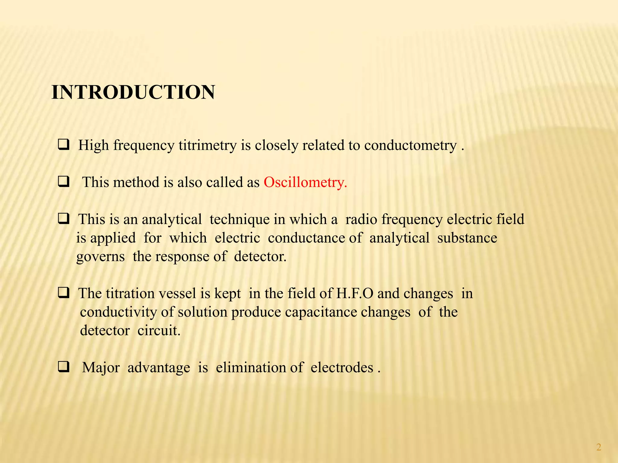
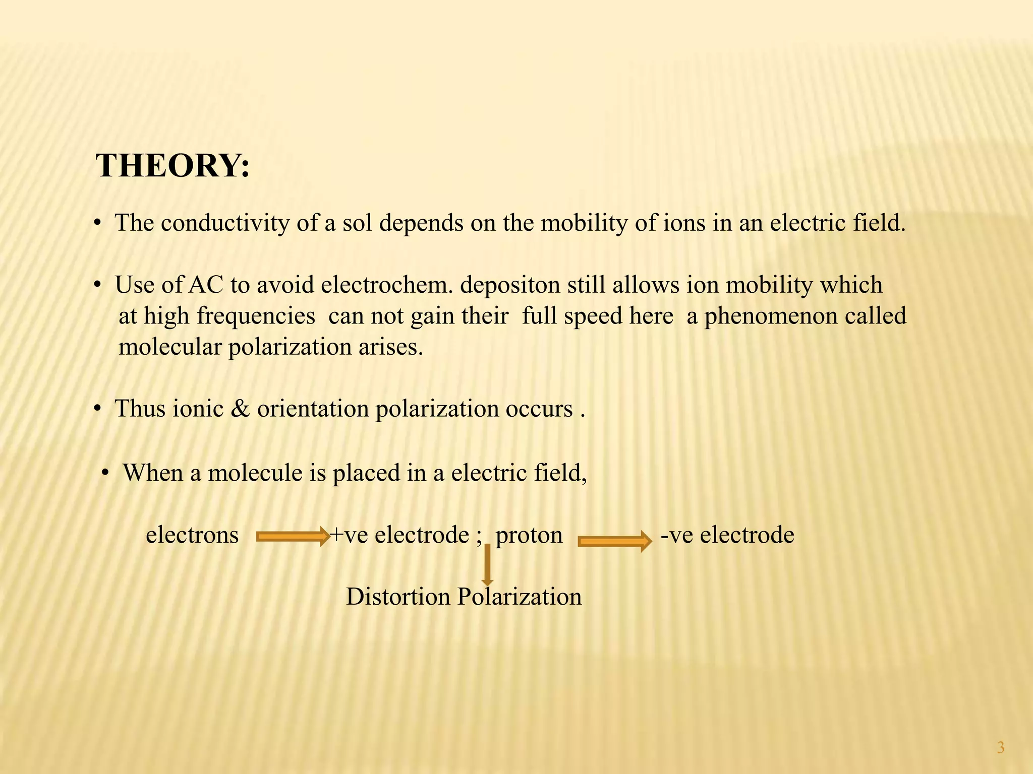
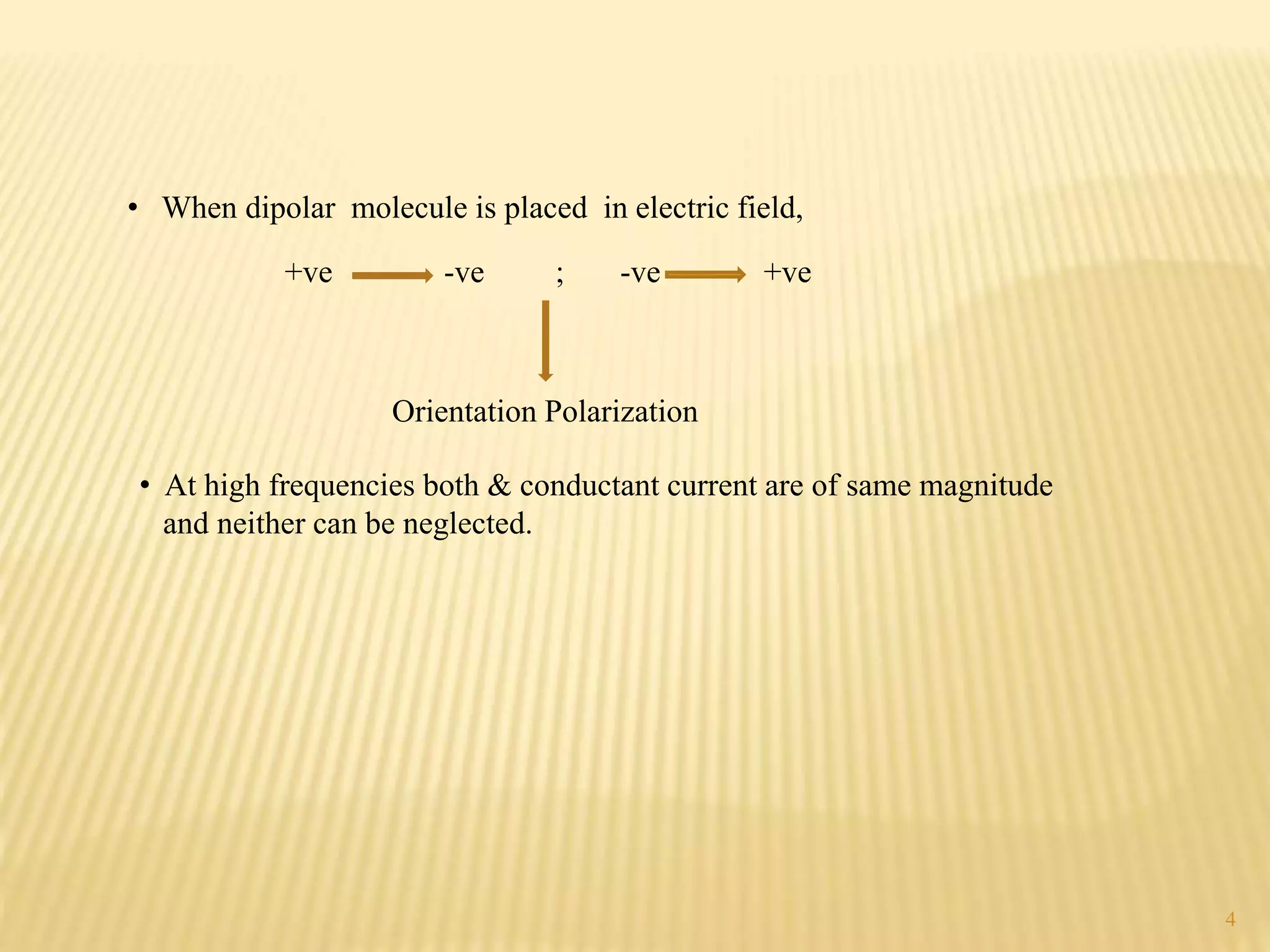
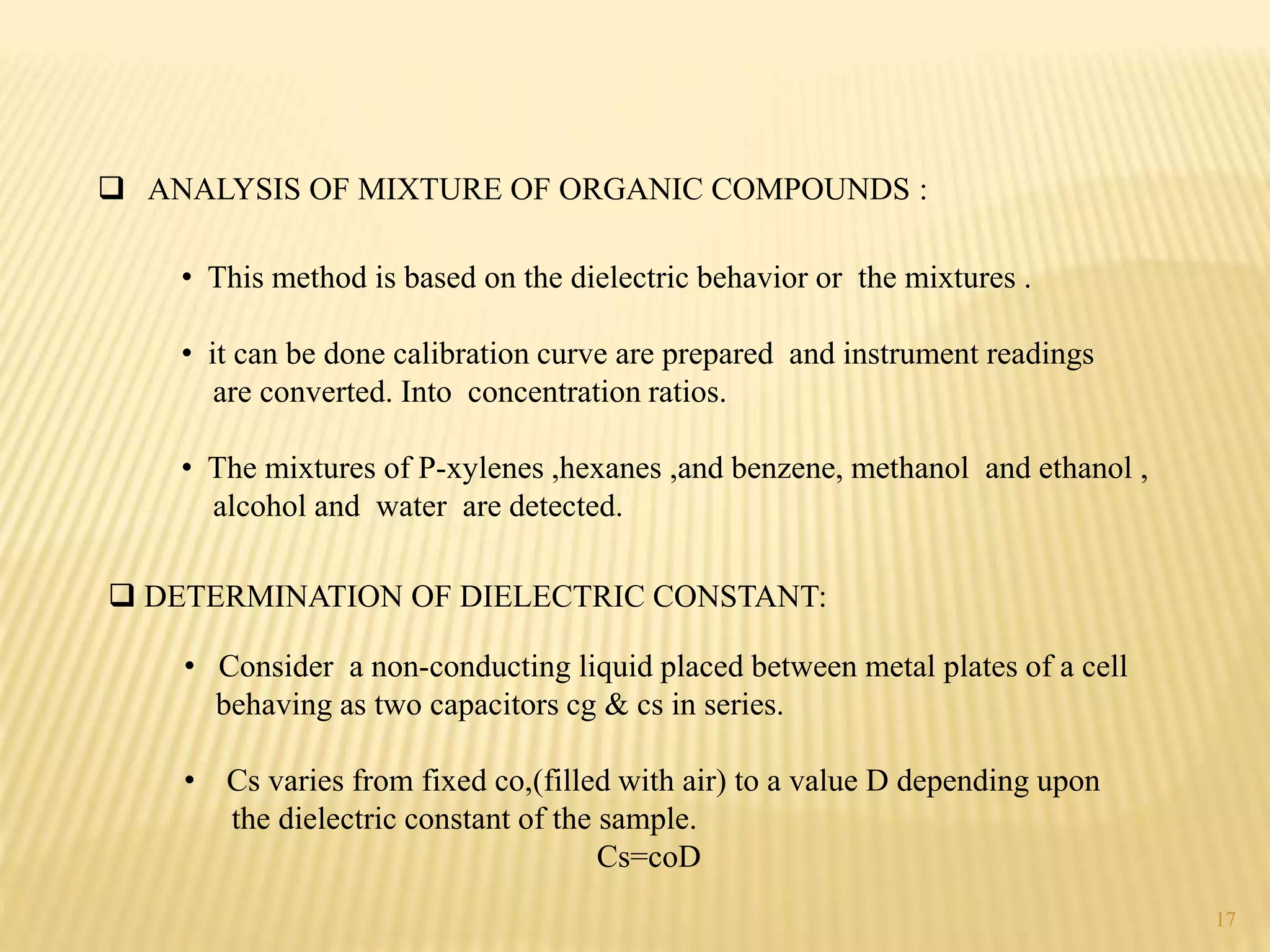
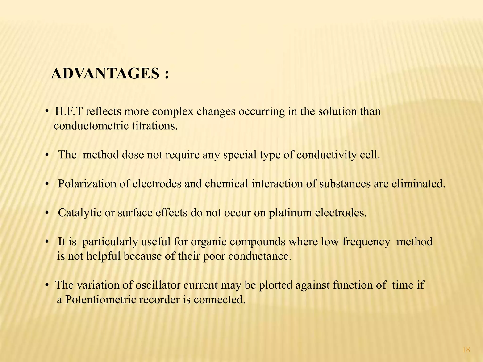


High frequency titrations (HFT) is an analytical technique utilizing radio frequency electric fields to measure the conductivity of solutions without the use of electrodes. This method provides advantages such as eliminating polarization effects and being particularly useful for organic compounds, although it is complex and less sensitive compared to traditional methods. Various applications include acid-base, complexometric, and precipitation titrations, as well as analysis of organic compound mixtures.


