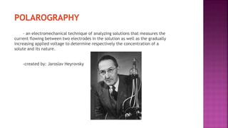
This document discusses polarography, which is a technique for analyzing solutions using two electrodes - a dropping mercury working electrode and a reference electrode. It provides details on:
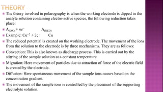
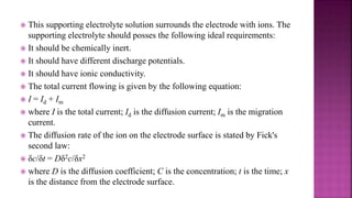
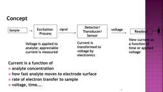
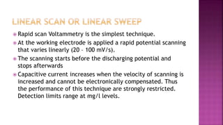
1. How polarography works by applying a voltage to induce a redox reaction and measuring the resulting current.
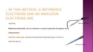
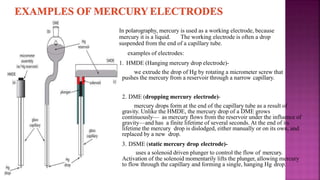
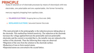
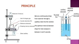
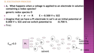
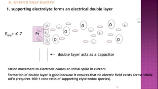
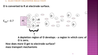
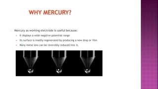
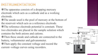
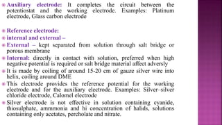
2. The components needed, including the dropping mercury electrode, reference electrode, and a supporting electrolyte.
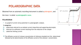
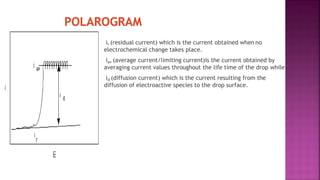
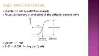
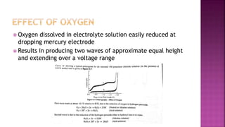
3. How polarograms are generated by plotting current vs. applied voltage and the different regions that can be seen on a polarogram.
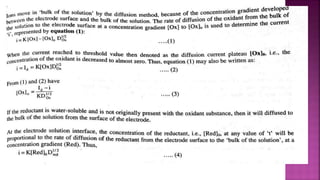
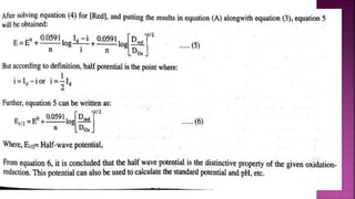
4. Factors that influence the diffusion current measured, such as concentration of the analyte, diffusion coefficient, and drop lifetime. Equations for calculating diffusion current are also presented.


![Polarography[1]](https://cdn.slidesharecdn.com/ss_thumbnails/polarography1-210816031327-thumbnail.jpg?width=640&height=640&fit=bounds)


![POLARGRAY_by_Shabnam_Faiz,_R.No_06[1].pptx](https://cdn.slidesharecdn.com/ss_thumbnails/polargraybyshabnamfaizr-220606070420-1e408d1d-thumbnail.jpg?width=640&height=640&fit=bounds)


