Download as PPSX, PPTX

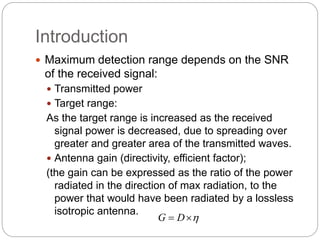
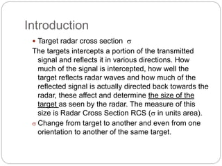
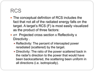
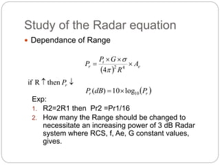
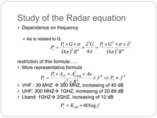
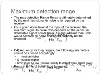
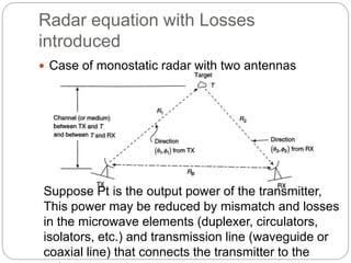
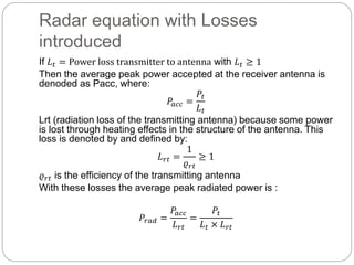
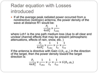
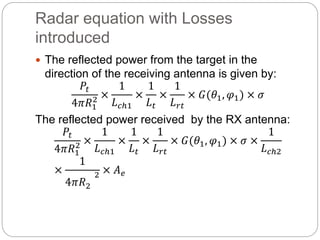

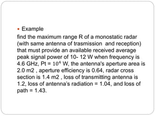

The document discusses radar equations and concepts including: 1) The radar equation relates maximum detection range to transmitted power, target radar cross section, antenna gain, and other factors. Range decreases as the fourth power of distance due to signal spreading. 2) Target radar cross section depends on the object's ability to intercept and reflect radar signals in the radar's direction. RCS can vary significantly based on the target and its orientation. 3) Losses are introduced in the radar equation from transmission inefficiencies, antenna losses, and signal attenuation over the transmission path. 4) For a given receiver sensitivity, maximum detection range increases with higher transmitted power, antenna gain, frequency, and target RCS but


![Mimo [new]](https://cdn.slidesharecdn.com/ss_thumbnails/mimonew-150914045107-lva1-app6892-thumbnail.jpg?width=640&height=640&fit=bounds)


!["GPS" Global Positioning System [PDF]](https://cdn.slidesharecdn.com/ss_thumbnails/globalpositioningsystemgpsmainpdf-101105164539-phpapp01-thumbnail.jpg?width=640&height=640&fit=bounds)