Download to read offline

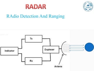

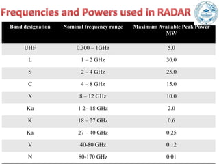


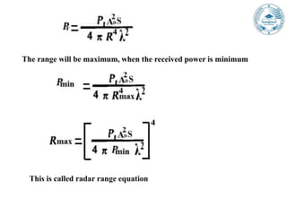
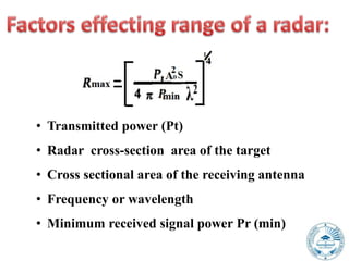


This document provides an overview of radar principles and technologies. It discusses the different radar frequency bands and power levels used. It then describes the basic components and functioning of pulsed radar systems, including how radar range is calculated from the time it takes a pulse to travel to a target and return. Continuous wave and pulse radar are the two main types discussed, along with Doppler radar. Factors influencing maximum radar range are also covered through the radar range equation.