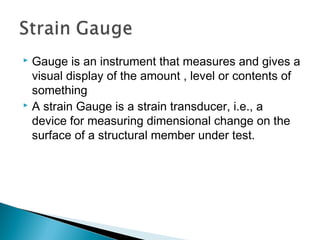
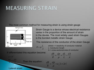
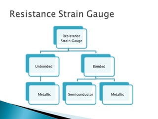
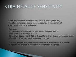
This document discusses strain measurement techniques. It introduces strain gauges as the most common method to measure strain. Strain gauges work by changing electrical resistance proportionally to the amount of strain. To accurately measure small resistance changes from strain, a Wheatstone bridge circuit is used to convert it to a voltage output. The document covers the basic principles of how strain gauges work and are used to measure static, transient, and dynamic strain through small changes in resistance.
Measuring Strain with Electrical Resistance Gauges
1.
2.
3. INTRODUCTION
Why to measure strain?
Strain Measuring Techniques
Strain Gauge
Points to design Strain Gauge
Resistance Strain gauge
Wheat stone Bridge
4. Strain is the amount of deformation of a body to an applied force
axial
lateral
For axial direction from the figure above
L
L
a
∆
=ε
5. Utility of strain measurement as a means of determining
maximum stress values, or in specialised transducers to
measure force, pressure, acceleration, torque, etc.
Desirability to avoid the use of large factors of safety in
the design of aircraft and automatic control equipment
due to mass/inertia considerations.
Necessity of experimental verification of strain in
complex physical systems where strain can only be
approximately estimated even with the most rigorous
analytical methods.
7. Gauge is an instrument that measures and gives a
visual display of the amount , level or contents of
something
A strain Gauge is a strain transducer, i.e., a
device for measuring dimensional change on the
surface of a structural member under test.
8. The Mechanical strain gauges are used in
applications where long gauge lengths and robust
instruments are required, e.g., in standard tensile
testing and in structural steel work. However they
work satisfactorily only for static extensions; their use
to dynamic strains is restricted by inertia and
frictional effects.
They are replaced by electrical strain gauges due to
inherent advantages of electrical systems and the
capability to measure dynamic conditions at very high
frequencies.
9. 1. Extremely small size and negligible mass
2. Simple and easy attachment to the specimen under test
3. Good response in unison with changes in the surface to which it is
fixed.
4. Non-interference with the stiffness and other characteristics of the
member over which it is mounted
5. High sensitivity in the direction of measured strain but low
sensitivity in the transverse plane.
6. High speed of response ; negligible time lag
7. Capability to indicate static , transient and dynamic strain
8. Inexpensive , reliable and readily available
10. The most common method for measuring strain is using strain gauge
Strain Gauge is a device whose electrical resistance
varies in the proportion of the amount of strain
in the device. The most widely used strain Gauges
is the bonded metallic strain Gauge
The resistance of the conductor of the strain Gauge
A
L
R ρ=
where r = resistivity of conductor material
L =conductor length
A = cross-sectional area of conductor
If differentiated this equation become:
A
dA
L
dLd
R
dR
−+=
ρ
ρ
A
D
dD
A
dA
DA
2
2
≈
≈
Then the equation :
( )νε
ρ
ρ
21++= a
d
R
dR
Lateral strain
11.
12. These gauges are bonded or cemented directly
onto the surface of the structural member which is
being examined. Any change in strain in the
member are transmitted directly to the gauge
Material.
13. The resistance wires are stretched around rigid
and electrically insulated pins on two frames A
and B which can move relative to each other. The
spring loaded mechanism hold’s the frames
together.
14. Strain measurement involves a very small quantity (a few me)
Therefore to measure strain, requires accurate measurement of
a very small change of resistance
Example:
To measure a strain of 500 µε, with strain Gauge factor= 2
Than ∆R=Sxε = 2x500 µε or 0.1%
If the strain Gauge has R=120 Ω (typical for a strain Gauge to measure strain)
∆R=0.12 Ω (it’s a very small resistance change)
To measure such a small change in resistance, a bridge circuit is needed
to convert this change in resistance to the change in voltage
15. WHEATSTONE BRIDGE
For the Wheatstone bridge arrangement
so V
RR
R
RR
R
V
+
−
+
=
41
4
32
3
For example strain Gauge is in R3
The initial resistance of strain Gauge is R3i
Then to balance the bridge
R3iR1-R4R2=0, then if the strain is strained
R3=R3i+∆R3
))(( 41332
31
RRRRR
RR
VV
i
so
+∆++
∆
=
∆R3 small compared to R3i and can be
neglected
Vo become linier function of ∆R3 then
( )
is
i
oa
RSRV
RR
V
32
2
32 +
=ε
16. A single strain Gauge has a nominal resistance of 120 Ω and a Gauge factor
of 2.06. For a quarter bridge with 120 Ω fixed resistor, what will be the
voltage output with a strain of 1000 µstrain for a supply voltage of 3 V?
Solution:
Using equation ( )
is
i
oa
RSRV
RR
V
32
2
32 +
=ε
mVV
xxx
V
x
out
out
544.1
12012006.23
)120120(
101000
2
6
=
+
=−
17. quarter bridge circuit half bridge circuit full bridge circuit
Temperature compensation
Any change in resistance of RG caused by change
in temperature will be compensated by the dummy
Gauge resulting in only strain imposed in active RG
will be detected