Downloaded 133 times


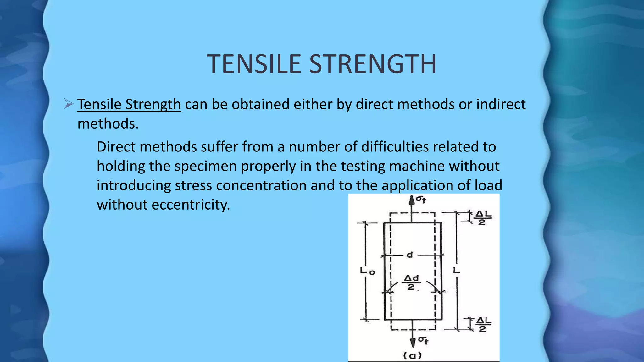


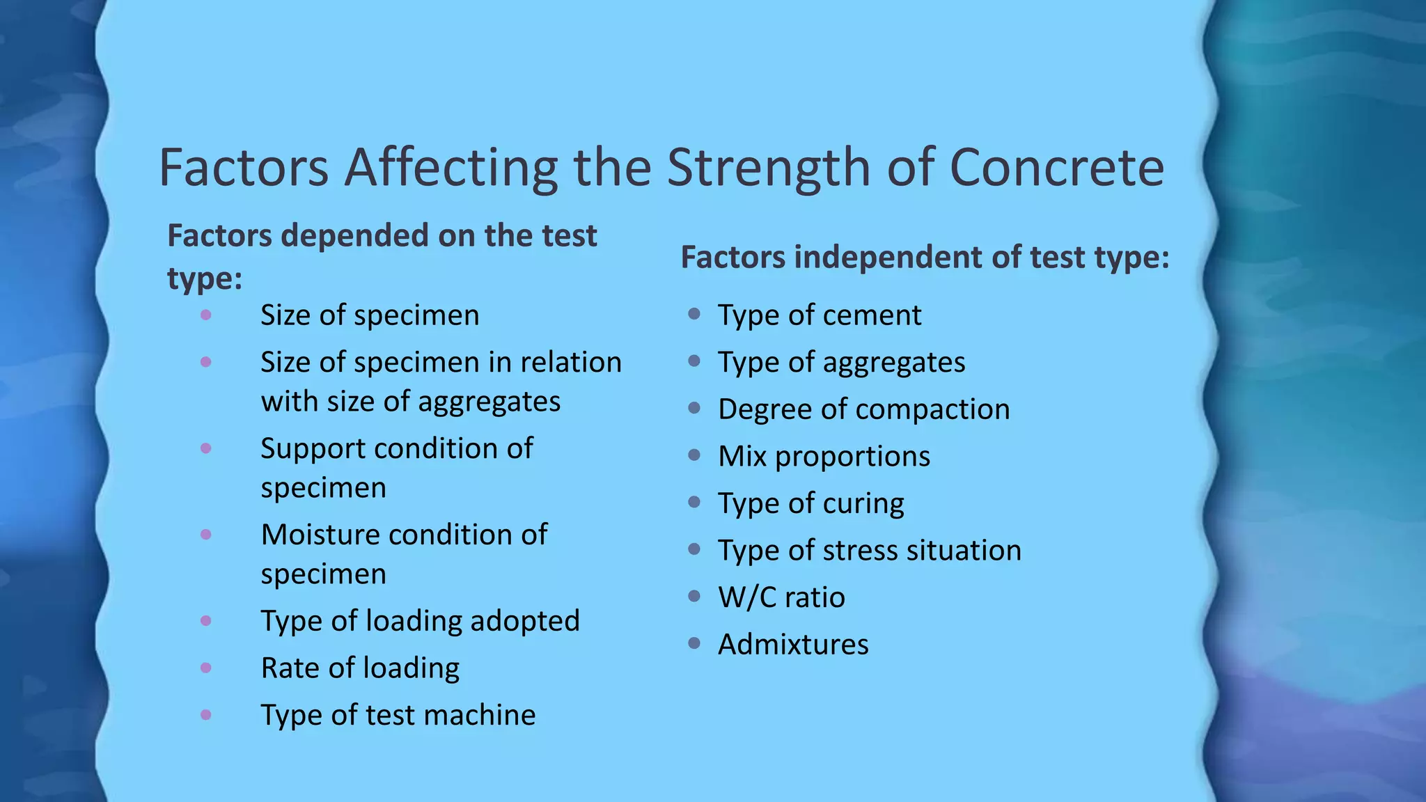
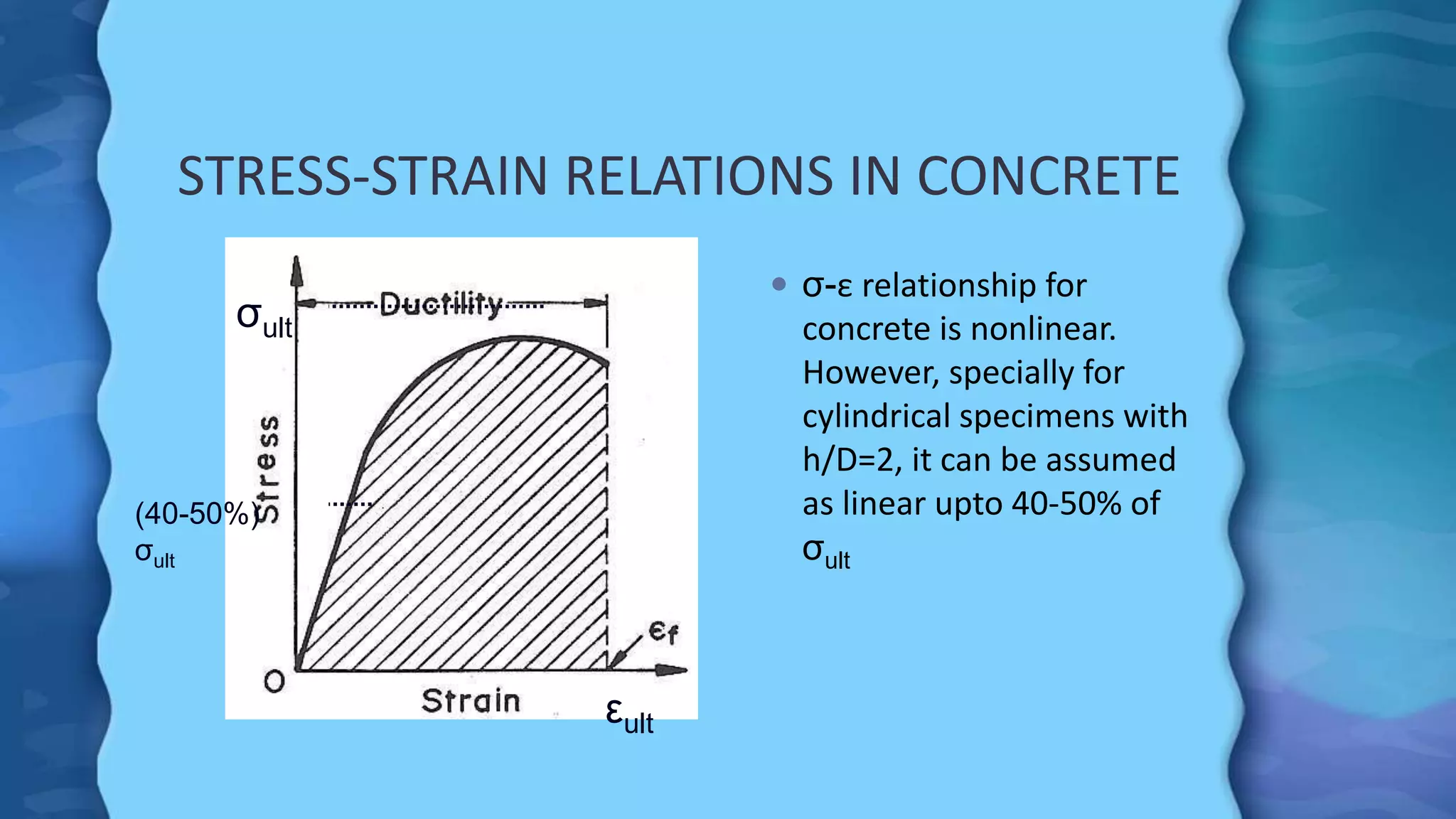
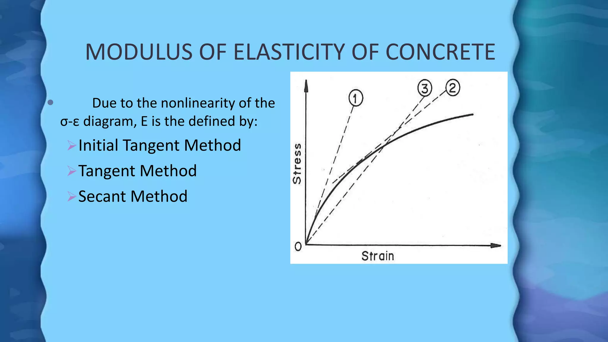

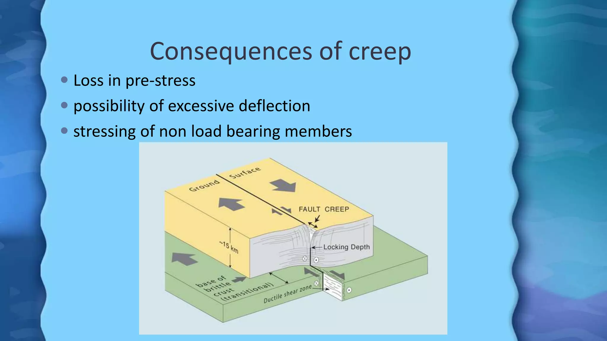


This document discusses various properties of hardened concrete, including its strength and stress-strain behavior. It describes how compressive, tensile, and splitting tensile strengths are measured through standard tests. The compressive strength of concrete is influenced by factors like the water-cement ratio, degree of compaction, cement type, and curing method. The stress-strain curve for concrete is nonlinear, and its modulus of elasticity can be defined using different methods. The document also covers creep and shrinkage in concrete, how they occur over time, and their effects on structural integrity.


