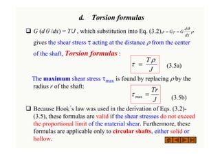
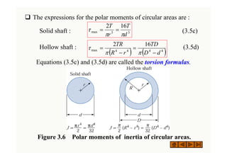
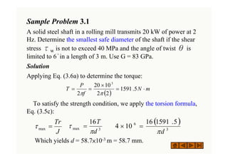
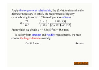
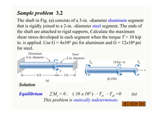
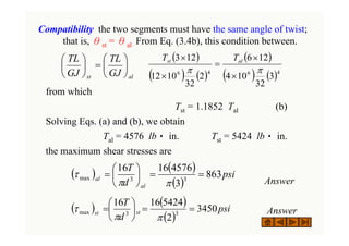
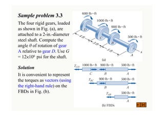
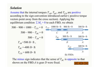
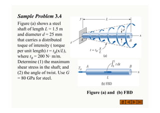
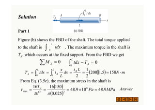
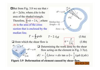
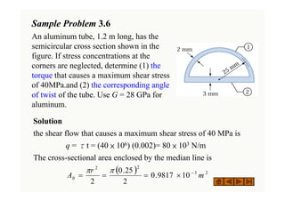
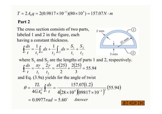
Bending Stresses are important in the design of beams from strength point of view. The present source gives an idea on theory and problems in bending stresses.
This session covers the basics that are required to analyse indeterminate trusses to maximum of two degree indeterminacy which includes,
strain energy stored due to axial loads and bending stresses,
maxwell's reciprocal deflection theorem,
Betti's law,
castigliano's theorems,
problems based on castigliano's theorems on beams and frames,
unit load method,
problems on trusses with unit load method,
lack of fit in trusses,
temperature effect on truss members.
Torsión se refiere al torcimiento de una barra recta al ser cargada por momentos (o pares de torsión) que tienden a producir rotación con respecto al eje longitudinal de la barra.
Prestress loss due to friction & anchorage take upAyaz Malik
This document provides a detailed procedure for calculating prestress loss due to anchorage take-up. Prestress Loss due to friction is also discussed in detail.
This document gives the class notes of Unit-8: Torsion of circular shafts and elastic stability of columns. Subject: Mechanics of materials.
Syllabus contest is as per VTU, Belagavi, India.
Notes Compiled By: Hareesha N Gowda, Assistant Professor, DSCE, Bengaluru-78.
Sachpazis:Terzaghi Bearing Capacity Estimation in simple terms with Calculati...Dr.Costas Sachpazis
Terzaghi's soil bearing capacity theory, developed by Karl Terzaghi, is a fundamental principle in geotechnical engineering used to determine the bearing capacity of shallow foundations. This theory provides a method to calculate the ultimate bearing capacity of soil, which is the maximum load per unit area that the soil can support without undergoing shear failure. The Calculation HTML Code included.
Forklift Classes Overview by Intella PartsIntella Parts
Discover the different forklift classes and their specific applications. Learn how to choose the right forklift for your needs to ensure safety, efficiency, and compliance in your operations.
For more technical information, visit our website https://intellaparts.com
Final project report on grocery store management system..pdfKamal Acharya
In today’s fast-changing business environment, it’s extremely important to be able to respond to client needs in the most effective and timely manner. If your customers wish to see your business online and have instant access to your products or services.
Online Grocery Store is an e-commerce website, which retails various grocery products. This project allows viewing various products available enables registered users to purchase desired products instantly using Paytm, UPI payment processor (Instant Pay) and also can place order by using Cash on Delivery (Pay Later) option. This project provides an easy access to Administrators and Managers to view orders placed using Pay Later and Instant Pay options.
In order to develop an e-commerce website, a number of Technologies must be studied and understood. These include multi-tiered architecture, server and client-side scripting techniques, implementation technologies, programming language (such as PHP, HTML, CSS, JavaScript) and MySQL relational databases. This is a project with the objective to develop a basic website where a consumer is provided with a shopping cart website and also to know about the technologies used to develop such a website.
This document will discuss each of the underlying technologies to create and implement an e- commerce website.
Democratizing Fuzzing at Scale by Abhishek Aryaabh.arya
Presented at NUS: Fuzzing and Software Security Summer School 2024
This keynote talks about the democratization of fuzzing at scale, highlighting the collaboration between open source communities, academia, and industry to advance the field of fuzzing. It delves into the history of fuzzing, the development of scalable fuzzing platforms, and the empowerment of community-driven research. The talk will further discuss recent advancements leveraging AI/ML and offer insights into the future evolution of the fuzzing landscape.
About
Indigenized remote control interface card suitable for MAFI system CCR equipment. Compatible for IDM8000 CCR. Backplane mounted serial and TCP/Ethernet communication module for CCR remote access. IDM 8000 CCR remote control on serial and TCP protocol.
• Remote control: Parallel or serial interface.
• Compatible with MAFI CCR system.
• Compatible with IDM8000 CCR.
• Compatible with Backplane mount serial communication.
• Compatible with commercial and Defence aviation CCR system.
• Remote control system for accessing CCR and allied system over serial or TCP.
• Indigenized local Support/presence in India.
• Easy in configuration using DIP switches.
Technical Specifications
Indigenized remote control interface card suitable for MAFI system CCR equipment. Compatible for IDM8000 CCR. Backplane mounted serial and TCP/Ethernet communication module for CCR remote access. IDM 8000 CCR remote control on serial and TCP protocol.
Key Features
Indigenized remote control interface card suitable for MAFI system CCR equipment. Compatible for IDM8000 CCR. Backplane mounted serial and TCP/Ethernet communication module for CCR remote access. IDM 8000 CCR remote control on serial and TCP protocol.
• Remote control: Parallel or serial interface
• Compatible with MAFI CCR system
• Copatiable with IDM8000 CCR
• Compatible with Backplane mount serial communication.
• Compatible with commercial and Defence aviation CCR system.
• Remote control system for accessing CCR and allied system over serial or TCP.
• Indigenized local Support/presence in India.
Application
• Remote control: Parallel or serial interface.
• Compatible with MAFI CCR system.
• Compatible with IDM8000 CCR.
• Compatible with Backplane mount serial communication.
• Compatible with commercial and Defence aviation CCR system.
• Remote control system for accessing CCR and allied system over serial or TCP.
• Indigenized local Support/presence in India.
• Easy in configuration using DIP switches.
COLLEGE BUS MANAGEMENT SYSTEM PROJECT REPORT.pdfKamal Acharya
The College Bus Management system is completely developed by Visual Basic .NET Version. The application is connect with most secured database language MS SQL Server. The application is develop by using best combination of front-end and back-end languages. The application is totally design like flat user interface. This flat user interface is more attractive user interface in 2017. The application is gives more important to the system functionality. The application is to manage the student’s details, driver’s details, bus details, bus route details, bus fees details and more. The application has only one unit for admin. The admin can manage the entire application. The admin can login into the application by using username and password of the admin. The application is develop for big and small colleges. It is more user friendly for non-computer person. Even they can easily learn how to manage the application within hours. The application is more secure by the admin. The system will give an effective output for the VB.Net and SQL Server given as input to the system. The compiled java program given as input to the system, after scanning the program will generate different reports. The application generates the report for users. The admin can view and download the report of the data. The application deliver the excel format reports. Because, excel formatted reports is very easy to understand the income and expense of the college bus. This application is mainly develop for windows operating system users. In 2017, 73% of people enterprises are using windows operating system. So the application will easily install for all the windows operating system users. The application-developed size is very low. The application consumes very low space in disk. Therefore, the user can allocate very minimum local disk space for this application.
Water scarcity is the lack of fresh water resources to meet the standard water demand. There are two type of water scarcity. One is physical. The other is economic water scarcity.
Cosmetic shop management system project report.pdfKamal Acharya
Buying new cosmetic products is difficult. It can even be scary for those who have sensitive skin and are prone to skin trouble. The information needed to alleviate this problem is on the back of each product, but it's thought to interpret those ingredient lists unless you have a background in chemistry.
Instead of buying and hoping for the best, we can use data science to help us predict which products may be good fits for us. It includes various function programs to do the above mentioned tasks.
Data file handling has been effectively used in the program.
The automated cosmetic shop management system should deal with the automation of general workflow and administration process of the shop. The main processes of the system focus on customer's request where the system is able to search the most appropriate products and deliver it to the customers. It should help the employees to quickly identify the list of cosmetic product that have reached the minimum quantity and also keep a track of expired date for each cosmetic product. It should help the employees to find the rack number in which the product is placed.It is also Faster and more efficient way.
Explore the innovative world of trenchless pipe repair with our comprehensive guide, "The Benefits and Techniques of Trenchless Pipe Repair." This document delves into the modern methods of repairing underground pipes without the need for extensive excavation, highlighting the numerous advantages and the latest techniques used in the industry.
Learn about the cost savings, reduced environmental impact, and minimal disruption associated with trenchless technology. Discover detailed explanations of popular techniques such as pipe bursting, cured-in-place pipe (CIPP) lining, and directional drilling. Understand how these methods can be applied to various types of infrastructure, from residential plumbing to large-scale municipal systems.
Ideal for homeowners, contractors, engineers, and anyone interested in modern plumbing solutions, this guide provides valuable insights into why trenchless pipe repair is becoming the preferred choice for pipe rehabilitation. Stay informed about the latest advancements and best practices in the field.
2. 3.1 Introduction
‰ In many engineering applications, members are required to
carry torsional loads.
‰ Consider the torsion of circular shafts. Because a circular
cross section is an efficient shape for resisting torsional loads.
Circular shafts are commonly used to transmit power in
rotating machinery.
‰ Also discuss another important application-torsion of thin-
walled tubes..
3. 3.1 Torsion of Circular Shafts
a. Simplifying assumptions
‰During the deformation, the cross sections are not distorted in
any manner-they remain plane, and the radius r does not
change. In addition, the length L of the shaft remains constant.
Figure 3.1
Deformation of
a circular shaft
caused by the
torque T. The
initially straight
line AB deforms
into a helix.
4. ‰ Based on these observations, we make the following
assumptions:
٠ Circular cross sections remain plane (do not warp) and
perpendicular to the axis of the shaft.
٠ Cross sections do not deform (there is no strain in the plane of
the cross section).
٠ The distances between cross sections do not change (the axial
normal strain is zero).
‰ Each cross section rotates as a rigid entity about the axis of
the shaft. Although this conclusion is based on the observed
deformation of a cylindrical shaft carrying a constant internal
torque, we assume that the result remains valid even if the
diameter of the shaft or the internal torque varies along the
length of the shaft.
5. b. Compatibility
‰ Because the cross sections are separated by an infinitesimal
distance, the difference in their rotations, denoted by the angle
dθ, is also infinitesimal.
‰ As the cross sections undergo the relative rotation dθ, CD
deforms into the helix CD. By observing the distortion of the
shaded element, we recognize that the helix angle γis the shear
strain of the element. (c) 2003 Brooks/Cole Publishing / Thomson Learning™
(c) 2003 Brooks/Cole Publishing / Thomson Learning™
6. From the geometry of Fig.3.2(a), we obtain DD´= ρ dθ=γdx ,
from which the shear strain γ is
(3.1)
The quantity dθ/dx is the angle of twist per unit length, where
θ is expressed in radians. The corresponding shear stress,
illustrated in Fig. 3.2 (b), is determined from Hooke´s law:
(3.2)
(c) 2003 Brooks/Cole Publishing / Thomson Learning
Figure 3.2 (a) Shear
strain of a material
element caused by
twisting of the shaft;
(b) the corresponding
shear stress.
ρ
θ
γ
dx
d
=
ρ
θ
γ
τ
dx
d
G
G =
=
7. ‰ the shear stress varies linearly with the radial distance ρ from
the axial of the shaft.
‰ The variation of the shear stress acting on the cross section is
illustrated in Fig. 3.3. The maximum shear stress, denoted by
τmax , occurs at the surface of the shaft.
‰ Note that the above derivations assume neither a constant
internal torque nor a constant cross section along the length of
the shaft.
Figure 3.3 Distribution of
shear stress along the
radius of a circular shaft.
ρ
θ
γ
τ
dx
d
G
G =
=
8. ‰ The shear force acting on this area is dP = τdA = G (dθ/dx)
ρ dA, directed perpendicular to the radius. Hence, the moment
(torque) of dP about the center o is ρ dP = G (dθ/dx) ρ 2dA.
Summing the contributions and equating the result to the
internal torque yields or
c. Equilibrium
‰ Fig. 3.4 shows a cross
section of the shaft
containing a
differential element of
area dA loaded at the
radial distance ρ from
the axis of the shaft.
Figure 3.4
Calculating the
Resultant of the
shear stress acting
on the cross
section. Resultant
is a couple equal
to the internal
torque T.
,
T
dP
A =
∫ ρ
T
dA
dx
d
G A =
∫
2
ρ
θ
9. Recognizing that is the polar moment of inertia of the cross-
sectional area, we can write this equation as G (dθ/dx) J = T , or
(3.3)
The rotation of the cross section at the free end of the shaft, called
the angle of twist θ , is obtained by integration:
(3.4a)
As in the case of a prismatic bar carrying a constant torque, then
reduces the torque-twist relationship
(3.4b)
Note the similarity between Eqs. (3.4) and the corresponding
formulas for axial deformation: and δ = PL/(EA)
GJ
T
dx
d
=
θ
( )
∫
=
L
o
dx
EA
P/
δ
dx
GJ
T
d
L
o
L
o ∫
∫ =
= θ
θ
GJ
TL
=
θ
10. Notes on the Computation of angle of Twist
٠ 1.In the U.S. Customary system, the consistent units are G [ psi ],
T [ lb.in ] , and L [ in.], and J [ in.4 ]; in the SI system, the
consistent units are G [ Pa ], T [ N.m ], L [ m ], and J [ m4 ].
٠ 2.The unit of θin Eqs. (3.4) is radians, regardless of which
system of unit is used in the computation.
٠ 3.Represent torques as vectors using the right-hand rule, as
illustrated in Fig. 3.5. The same sign convention applies to the
angle of twistθ.
Figure 3.5 Sign
Conventions
for Torque T
and angle of
twist Τ.
11. d. Torsion formulas
‰ G (dθ/dx) = T/J , which substitution into Eq. (3.2),
gives the shear stress τ acting at the distance ρ from the center
of the shaft, Torsion formulas :
(3.5a)
The maximum shear stress τmax is found by replacing ρ by the
radius r of the shaft:
(3.5b)
‰ Because Hook´s law was used in the derivation of Eqs. (3.2)-
(3.5), these formulas are valid if the shear stresses do not exceed
the proportional limit of the material shear. Furthermore, these
formulas are applicable only to circular shafts, either solid or
hollow.
J
T ρ
τ =
J
Tr
=
max
τ
ρ
θ
γ
τ
dx
d
G
G =
=
12. ‰ The expressions for the polar moments of circular areas are :
Solid shaft : (3.5c)
Hollow shaft : (3.5d)
Equations (3.5c) and (3.5d) are called the torsion formulas.
3
3
max
16
2
d
T
r
T
π
π
τ =
=
( ) ( )
4
4
4
4
max
16
2
d
D
TD
r
R
TR
−
=
−
=
π
π
τ
Figure 3.6 Polar moments of inertia of circular areas.
13. e. Power transmission
‰ Shafts are used to transmit power. The power ζ transmitted by a
torque T rotating at the angular speed ω is given by ζ =T ω,
where ω is measured in radians per unit time.
‰ If the shaft is rotating with a frequency of f revolutions per unit
time, then ω = 2π f , which gives ζ = T (2π f ). Therefore, the
torque can be expressed as
(3.6a)
‰ In SI units, ζ in usually measured in watts (1.0 W=1.0 N‧m/s)
and f in hertz (1.0 Hz = 1.0 rev/s); Eq. (3.6a) then determines
the torque T in N‧m.
‰ In U.S. Customary units with ζ in lb‧in./s and f in hertz,
Eq.(3.6a) calculates the torque T in lb‧in.
f
T
π
ζ
2
=
14. ‰ Because power in U.S. Customary units is often expressed in
horsepower (1.0 hp = 550 lb•ft/s = 396×103 lb•in./min), a
convenient form of Eq.(3.6a) is
which simplifies to
(3.6b)
( )
( )
( )
( )
hp
in
lb
rev
f
hp
in
lb
T
0
.
1
min
/
.
10
396
min
/
2
)
(
3
⋅
×
×
=
⋅
π
ζ
( )
( )
min
/
10
0
.
63
)
( 3
rev
f
hp
in
lb
T
ζ
×
=
⋅
15. f. Statically indeterminate problems
• Draw the required free-body diagrams and write the
equations of equilibrium.
• Derive the compatibility equations from the restrictions
imposed on the angles of twist.
• Use the torque- twist relationships in Eqs.(3.4) to express
the angles of twist in the compatibility equations in terms of
the torques.
• Solve the equations of equilibrium and compatibility for the
torques.
16. Sample Problem 3.1
A solid steel shaft in a rolling mill transmits 20 kW of power at 2
Hz. Determine the smallest safe diameter of the shaft if the shear
stress τw is not to exceed 40 MPa and the angle of twist θ is
limited to 6°in a length of 3 m. Use G = 83 GPa.
Solution
Applying Eq. (3.6a) to determine the torque:
To satisfy the strength condition, we apply the torsion formula,
Eq. (3.5c):
Which yields d = 58.7×10⁻³ m = 58.7 mm.
3
max
16
d
T
π
τ =
( )
m
N
f
P
T ⋅
=
×
=
= 5
.
1591
2
2
10
20
2
3
π
π
( )
3
6 5
.
1591
16
10
4
d
π
=
×
J
Tr
=
max
τ
17. Apply the torque-twist relationship, Eq. (3.4b), to determine the
diameter necessary to satisfy the requirement of rigidity
(remembering to convert θfrom degrees to radians):
From which we obtain d = 48.6×10⁻³ m = 48.6 mm.
To satisfy both strength and rigidity requirements, we must
choose the larger diameter-namely,
d = 58.7 mm. Answer
( )
( )( )
32
/
10
83
3
5
.
1591
180
6 4
9
d
π
π
×
=
⎟
⎠
⎞
⎜
⎝
⎛
GJ
TL
=
θ
18. Sample problem 3.2
The shaft in Fig. (a) consists of a 3-in. -diameter aluminum segment
that is rigidly joined to a 2-in. -diameter steel segment. The ends of
the shaft are attached to rigid supports, Calculate the maximum
shear stress developed in each segment when the torque T = 10 kip
in. is applied. Use G = 4×10⁶ psi for aluminum and G = 12×106 psi
for steel.
Solution
Equilibrium ΣMx = 0 , ( 10 × 103 ) -Tst -Tal =0 (a)
This problem is statically indeterminate.
19. Compatibility the two segments must have the same angle of twist;
that is, θst = θal From Eq. (3.4b), this condition between.
from which
Tst = 1.1852 Tal (b)
Solving Eqs. (a) and (b), we obtain
Tal = 4576 lb‧ in. Tst = 5424 lb‧ in.
the maximum shear stresses are
Answer
Answer
al
st GJ
TL
GJ
TL
⎟
⎠
⎞
⎜
⎝
⎛
=
⎟
⎠
⎞
⎜
⎝
⎛
( ) ( )
( )
psi
d
T
al
al
863
3
4576
16
16
3
3
max =
=
⎟
⎠
⎞
⎜
⎝
⎛
=
π
π
τ
( ) ( )
( )
psi
d
T
st
st
3450
2
5424
16
16
3
3
max =
=
⎟
⎠
⎞
⎜
⎝
⎛
=
π
π
τ
( )
( ) ( )
( )
( ) ( )4
6
4
6
3
32
10
4
12
6
2
32
10
12
12
3
π
π
×
×
=
×
× al
st T
T
20. Sample problem 3.3
The four rigid gears, loaded
as shown in Fig. (a), are
attached to a 2-in.-diameter
steel shaft. Compute the
angle θ of rotation of gear
A relative to gear D. Use G
= 12×106 psi for the shaft.
Solution
It is convenient to represent
the torques as vectors (using
the right-hand rule) on the
FBDs in Fig. (b).
21. Solution
Assume that the internal torques TAB, TBC, and TCD are positive
according to the sign convention introduced earlier ( positive torque
vectors point away from the cross section). Applying the
equilibrium condition ΣMx = 0 to each FBD, we obtain
500-900+1000-TCD = 0
500-900-TBC = 0
500-TAB = 0
TAB =500 lb· ft ,
TBC =-400 lb· ft
TCD = 600 lb· ft
The minus sign indicates that the sense of TBC is opposite to that
shown on the FBD.A is gear D were fixed.
22. This rotation is obtained by summing the angles of twist of the three
segments:
θA/D =θA/B+θB /C+θC/D
Using Eq.(3.4b), we obtain (converting the lengths to inches and
torques to pound-inches)
= 0.02827 rad = 1.620° Answer
The positive result indicates that the rotation vector of A relative to
D is in the positive x-direction: that is, θAD is directed
counterclockwise when viewed from A toward D.
GJ
L
T
L
T
L
T CD
CD
BC
BC
AB
AB
D
A
+
+
=
/
θ
( )( ) ( )( ) ( )( )
( )
[ ]( )6
4
10
12
32
/
2
12
4
12
600
12
3
12
400
12
5
12
500
×
×
×
+
×
×
−
×
×
=
π
23. Sample Problem 3.4
Figure (a) shows a steel
shaft of length L = 1.5 m
and diameter d = 25 mm
that carries a distributed
toque of intensity ( torque
per unit length) t = tB(x/L),
where tB = 200 N· m/m.
Determine (1) the maximum
shear stress in the shaft; and
(2) the angle of twist. Use G
= 80 GPa for steel.
Figure (a) and (b) FBD
24. Solution
Part 1
Figure (b) shows the FBD of the shaft. The total torque applied
to the shaft is . The maximum torque in the shaft is
TA, which occurs at the fixed support. From the FBD we get
From Eq. (3.5c), the maximum stress in the shaft is
Answer
∫
t
tdx
0
0
=
∑ X
M ∫ =
−
L
A
T
tdx
0
0
∫ ∫ =
=
=
L
B
L
B
A
L
t
dx
L
x
t
tdx
T
0 0 2
( )( ) m
N ⋅
=
= 150
5
.
1
200
2
1
( )
( )
MPa
Pa
d
TA
9
.
48
10
9
.
48
025
.
0
150
16
16 6
3
3
max =
×
=
=
=
π
π
τ
25. Part 2
The torque T acting on a cross section located at the distance x
from the fixed end can be found from the FBD in Fig. (c):
From Eq. (3.4a), the angle θ of twist of the shaft is
= Answer
∑ = 0
X
M 0
0
=
−
+ ∫
χ
A
T
tdx
T
∫ ∫ =
−
=
−
=
χ χ
0 0
2
dx
L
x
t
L
t
tdx
T
T B
B
A
( )
∫ ∫ =
−
=
=
L L
B
B
GJ
L
t
dx
x
L
LGJ
t
dx
GJ
T
0 0
2
2
2
3
2
θ
( )
( )( )( )
o
8
.
2
0489
.
0
025
.
0
32
/
10
80
3
5
.
1
200
4
9
2
=
=
×
rad
π
( )
−
= 2
2
2
x
L
L
tB
26. 3.3 Torsion of Thin-Walled
Tubes
‰ Simple approximate formulas
are available for thin-walled
tubes. Such members are
common in construction where
light weight is of paramount
importance.
‰ The tube to be prismatic (
constant cross section), but the
wall thickness t is allowed to
vary within the cross section.
The surface that lies midway
between the inner and outer
boundaries of the tube is called
the middle surface.
Figure 3.7 (a) Thin-walled
tube in torsion; (b) shear
stress in the wall of the tube.
27. ‰ If thickness t is small compared to the overall dimensions of the
cross section, the shear stressτinduced by torsion can be
shown to be almost constant through the wall thickness of the
tube and directed tangent to the middle surface, in Fig. (3.7b).
‰ At this time, it is convenient to introduce the concept of shear
flow q, defined as the shear force per unit edge length of the
middle surface.
‰ the shear flow q is
q = τt (3.7)
If the shear stress is not
constant through the wall
thickness, then τin Eq.
(3.7) should be viewed as
the average shear stress.
28. (c) Shear flows on wall element.
‰the shear flow is constant
throughout the tube. This
result can be obtained by
considering equilibrium of
the element shown in Fig.
3.7(c).
‰In labeling the shear flows,
we assume that q varies in
the longitudinal (x) as well
as the circumferential (s)
directions. The force acting
on each side of the element
is equal to the shear flow
multiplied by the edge
length, resulting in the
equilibrium equations .
∑ = 0
X
F 0
=
−
⎟
⎠
⎞
⎜
⎝
⎛
∂
∂
+ qdx
dx
ds
s
q
q
∑ = 0
S
F 0
=
−
⎟
⎠
⎞
⎜
⎝
⎛
∂
∂
+ qds
ds
dx
x
q
q
thereby proving that
the shear flow is constant throughout
the tube.
,
0
/
/ =
∂
∂
=
∂
∂ s
q
x
q
29. ‰ The shear force is dP = qds. The moment of the force about an
arbitrary point 0 is rdP = (qds)r, where r is the perpendicular
distance of 0 from the line of action of dP. The sum of these
moment must be equal to the applied torque T; that is,
(a)
Which the integral is taken over the closed curve formed by the
intersection of the middles surface and the cross section, called
the median line.
Figure 3.8 Calculating the
resultant of the shear
flow acting on the cross
section of the tube.
Resultant of a couple
equal to the internal
torque T.
∫
=
s
qrds
T
30. ‡But from Fig. 3.8 we see that r
ds = 2dAo, where dAo is the
area of the shaded triangle.
Therefore, ,where
Ao is the area of the cross
section that is enclosed by the
median line.
T = 2 A0q (3.8a)
‰ from which the shear flow is (3.8b)
∫ =
s
A
rds ,
0
2
∫
=
s
qrds
T
0
2A
T
q =
‰ Determining the work done by the shear
flow acting on the element in Fig. 3.7(c).
Figure 3.9 Deformation of element caused by shear flow.
( ) )
)(
(
2
1
tan
2
1
dx
qds
ce
dis
force
dU γ
=
×
=
31. Substituting γ=τ/G = q / Gt yields
(b)
The work U of the shear flow for the entire tube is obtained by
integrating Eq. (b) over the middle surface of the tube. Noting that
q and G are constants and t is independent of x,
(c)
Conservation of energy requires U to be equal to the work of the
applied torque that is, U = Tθ/2. After substituting the expression
for q from Eq. (3.8b) into Eq. (c),
dsdx
Gt
q
dU
2
2
=
∫
∫ ∫ =
⎟
⎠
⎞
⎜
⎝
⎛
=
s
L
s t
ds
G
L
q
dx
t
ds
G
q
U
0
2
2
2
2
θ
T
t
ds
G
L
A
T
s 2
1
2
2
2
0
=
⎟
⎟
⎠
⎞
⎜
⎜
⎝
⎛
∫
)
)(
(
2
1
dx
qds γ
dU =
0
2A
T
q =
32. The angle of twist of the tube is
(3.9a)
If t is constant, we have where S is the length of
the median line Therefore, Eq. (3.9a) becomes
( constant t) (3.9b)
‰ If the tube is not cylindrical, its cross sections do not remain
plane but tend to warp. Tube with very thin walls can fail by
bucking which the stresses are still within their elastic ranges.
steel tubes of circular cross section require r/t <50 to forestall
buckling due to torsion.
‰ Shape re-entrant corners in the cross section of the tube should
also be avoided because they cause stress concentration. The
shear stress at the inside boundary of a corner can be
considerably higher than the average stress.
∫
=
s t
ds
GA
TL
2
0
4
θ
( )
∫ =
s
t
S
t
ds ,
/
/
t
GA
TLS
2
0
4
=
θ
33. 3.5 Figure (a)
Sample Problem 3.5
A steel tube with the cross section shown carries a torque T. The
tube is 6 ft long and has a constant wall thickness of 3/8 in. (1)
Compute the torsional stiffness k = T/θof the tube. (2) If the tube is
twisted through 0.5°, determine the shear stress in the wall of the
tube. Use G =12 × 106 psi. and neglect stress concentrations at the
corners. Solution
Part1
Because the wall thickness is
constant, the angle of twist is given by
Eq. (3.9b):
Therefore, the torsional stiffness of
the tube can be computed from
t
GA
TLS
2
0
4
=
θ
LS
t
GA
T 2
0
4
=
=
θ
κ
34. The area enclosed by the median line is
And the length of the median line is
Consequently, the torsional stiffness becomes
= 135.0 × 10³ lb· in./deg Answer
Part 2
The toque required to produce an angle of twist of 0.5° is
T = kθ= (135.0 × 10³)(0.5) = 67.5 × 10³ lb· in.
which results in the shear flow
The corresponding shear stress is Answer
=
×
= height
h
averagewit
A0 ( ) 2
.
25
5
2
4
6
in
=
⎟
⎠
⎞
⎜
⎝
⎛ +
.
20
.
20
5
1
2
4
6 2
2
in
S =
+
+
+
=
psi
t
q
3600
8
/
3
1350
=
=
=
τ
( )( ) ( )
( )( )
rad
in
lb /
.
10
735
.
7
20
.
20
12
6
8
/
3
25
10
12
4 6
2
6
⋅
×
=
×
×
=
κ
( )
.
/
1350
25
2
10
5
.
67
2
3
0
in
lb
A
T
q =
×
=
=
35. Sample Problem 3.6
An aluminum tube, 1.2 m long, has the
semicircular cross section shown in the
figure. If stress concentrations at the
corners are neglected, determine (1) the
torque that causes a maximum shear stress
of 40MPa.and (2) the corresponding angle
of twist of the tube. Use G = 28 GPa for
aluminum.
Solution
the shear flow that causes a maximum shear stress of 40 MPa is
q = τt = (40 × 106) (0.002)= 80 × 103 N/m
The cross-sectional area enclosed by the median line is
( ) 2
3
2
2
0 10
9817
.
0
2
25
.
0
2
m
r
A −
×
=
=
=
π
π
36. Part 2
where S1 and S2 are the lengths of parts 1 and 2, respectively.
and Eq. (3.9a) yields for the angle of twist
Answer
2
2
1 2
1
1
2
1
1
1
t
S
t
S
ds
t
ds
t
t
ds
s s
s
+
=
+
= ∫ ∫
∫
( ) ( ) 94
.
55
3
25
2
2
25
2
2
1
=
+
=
+
=
∫
π
γ
πγ
t
t
t
ds
s
( )
( )( )
( )
94
.
55
10
09817
10
28
4
2
.
1
07
.
157
4 2
3
9
2
0
−
×
×
=
= ∫s t
ds
GA
TL
θ
o
60
.
5
0977
.
0 =
= rad
m
N
q
A
T ⋅
=
×
×
=
= −
07
.
157
)
10
80
)(
10
9817
.
0
(
2
2 3
3
0
The cross section consists of two parts,
labeled 1 and 2 in the figure, each
having a constant thickness.