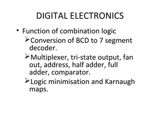
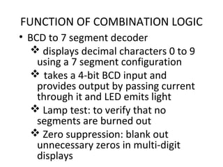
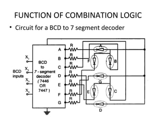
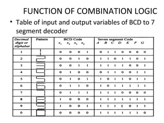
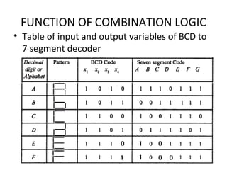
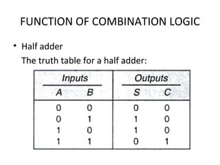
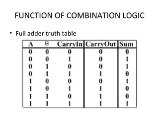
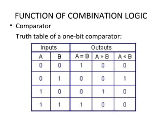
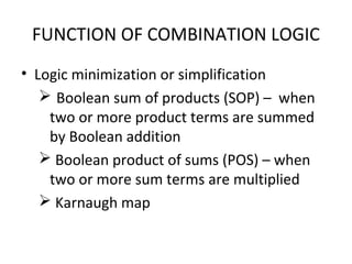
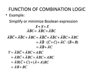
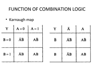
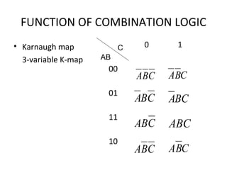
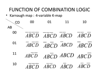
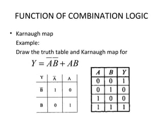
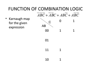
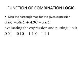
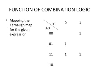
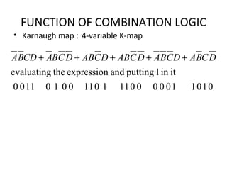
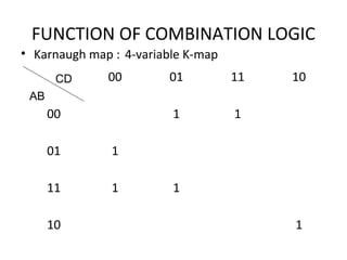
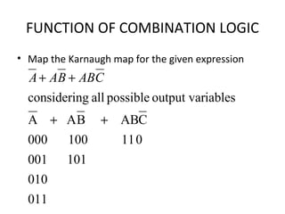
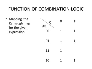
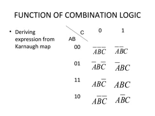
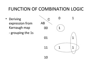
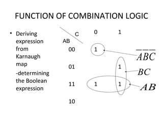
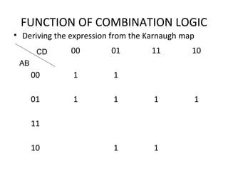
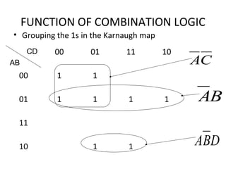
DIGITAL ELECTRONICS
CHAPTER 3
DEE 204
DIGITAL ELECTRONICS
• Function of combination logic
Conversion of BCD to 7 segment
decoder.
Multiplexer, tri-state output, fan
out, address, half adder, full
adder, comparator.
Logic minimisation and Karnaugh
maps.
FUNCTION OF COMBINATION LOGIC
• BCD to 7 segment decoder
 displays decimal characters 0 to 9
using a 7 segment configuration
 takes a 4-bit BCD input and
provides output by passing current
through it and LED emits light
 Lamp test: to verify that no
segments are burned out
 Zero suppression: blank out
unnecessary zeros in multi-digit
displays
FUNCTION OF COMBINATION LOGIC
• Circuit for a BCD to 7 segment decoder
FUNCTION OF COMBINATION LOGIC
• Table of input and output variables of BCD to 7
segment decoder
FUNCTION OF COMBINATION LOGIC
• Table of input and output variables of BCD to
7 segment decoder
FUNCTION OF COMBINATION LOGIC
• Multiplexer (MUX)
- also known as data selector
- is a device that allows digital information
from several sources to be routed onto a
single line for transmission over that line to a
common destination
- has several input lines and single output line
FUNCTION OF COMBINATION LOGIC
• Block diagram for a 1-of-n data
selector/multiplexer
FUNCTION OF COMBINATION LOGIC
• Multiplexer
For an 8-input MUX
with truth table:
INPUTS OUTPUTS
A2 A1 A0 Y
0 0 0 0
0 0 1 1
0 1 0 0
0 1 1 1
1 0 0 0
1 0 1 1
1 1 0 1
1 1 1 0
FUNCTION OF COMBINATION LOGIC
• Multiplexer
The connection to a 74LS151 IC is as shown:
FUNCTION OF COMBINATION LOGIC
• Tri-state logic
- normal logic circuits only have two
output states; HIGH and LOW
- in complex digital systems a number of
gate inputs may be required, causing
certain operation problems
FUNCTION OF COMBINATION LOGIC
Related problems:
 Transistor-transistor-logic (TTL)
totem-pole outputs or CMOS active
pull-up/pull-down outputs can’t be
connected together
 open-collector outputs can be
connected together with common
collector but resistor connected
externally, loading and speed
FUNCTION OF COMBINATION LOGIC
• Problems solved by
- developing special circuits with one more
output state known as third state or high
impedance state
- usually used as buffer gates
- modification of NAND gate with addition of
diodes D1 and D2 and an inverter gate
FUNCTION OF COMBINATION LOGIC
• Fan-out
- maximum number of inputs of several gates
that can be driven by the output of a logic
gate
- maximum number of inputs of the same IC
family that the gate can drive maintaining its
output levels within specified limits
FUNCTION OF COMBINATION LOGIC
• Fan-in
- the number of inputs
- at hardware level, it provides
information about the intrinsic speed of
the gate itself
- increases or decreases the propagation
delay
FUNCTION OF COMBINATION LOGIC
• Address:
- location in memory
- indicates the positions of instructions
and data in the memory
- starts with the number ‘0’ and up to the
largest address
FUNCTION OF COMBINATION LOGIC
• Half adder
- adds two bits and produces a sum and carry
output
- accepts two binary digits on inputs and
produces two binary digits on outputs, a sum
bit and a carry bit
Rules of binary addition
0 + 0 = 0
0 + 1 = 1
1 + 0 = 1
1 + 1 = 10
FUNCTION OF COMBINATION LOGIC
• Half-adder
The logic symbol
and logic diagram
for a half-adder:
FUNCTION OF COMBINATION LOGIC
• Half adder
The truth table for a half adder:
FUNCTION OF COMBINATION LOGIC
• Full adder
- has an input carry while the half-adder does
not
- accepts two input bits and an input carry and
generates a sum output and an output carry
FUNCTION OF COMBINATION LOGIC
• Full adder logic symbol
FUNCTION OF COMBINATION LOGIC
• Full adder logic diagram
( ) inout CBAABC ⊕+=
( ) inCBAS ⊕⊕=
FUNCTION OF COMBINATION LOGIC
• Full adder truth table
FUNCTION OF COMBINATION LOGIC
• Comparators
- a special combinational circuit designed
primarily to compare the relative magnitude
of two binary numbers
- for two n-bit numbers A and B as inputs, the
outputs could be either A=B, A<B or A>B
- depending on the relative magnitudes, one
of the outputs will be HIGH
FUNCTION OF COMBINATION LOGIC
• Comparator
The block diagram
of a n-bit
comparator:
FUNCTION OF COMBINATION LOGIC
• Comparator
Logic diagram of a one-bit comparator:
FUNCTION OF COMBINATION LOGIC
• Comparator
Truth table of a one-bit comparator:
FUNCTION OF COMBINATION LOGIC
• Logic minimization or simplification
 Boolean sum of products (SOP) – when
two or more product terms are summed
by Boolean addition
 Boolean product of sums (POS) – when
two or more sum terms are multiplied
 Karnaugh map
FUNCTION OF COMBINATION LOGIC
• The sum of products (SOP) form
Example:
ACCBABA
DCBCDEABC
ABCAB
++
++
+
FUNCTION OF COMBINATION LOGIC
• Example:
Convert Boolean expression to SOP form
( )
( )( )
( ) CBAc
DCBBAb
EFCDBABa
++
+++
++
)
)
)
FUNCTION OF COMBINATION LOGIC
• Solution
 An SOP expression is ‘1’ if one or more of the product terms
is ‘1’
( )
( )( )
( ) ( ) ( ) CBCACBACBACBAc
BDBCBBADACABDCBBAb
BEFBCDABEFCDBABa
+=+=+=++
+++++=+++
++=++
)
)
)
FUNCTION OF COMBINATION LOGIC
• The product of sums (POS) form
Example:
( )( )
( )( )( )
( )( )( )CACBABA
DCBEDCCBA
CBABA
++++
++++++
+++
FUNCTION OF COMBINATION LOGIC
• Example:
Convert Boolean expression to POS form
( )( )( )
( )( )
( )( )
( )( )( )( )( )DCBADCBADCBADCBADCBA
DCBADCBAAADCBDCB
DCBADCBADDCBACBA
DCBADCBCBA
+++++++++++++++
++++++=+++=++
++++++=+++=++
+++++++
asformPOSthegivingthus,
AorAvariablemissingistermsecondthegconsiderin
DorDvariablemissingisfirst termthegconsiderin
FUNCTION OF COMBINATION LOGIC
• Example:
Simplify or minimize Boolean expression
FUNCTION OF COMBINATION LOGIC
• Example:
Simplify or minimize Boolean expression
FUNCTION OF COMBINATION LOGIC
• Karnaugh map
- a systematic method for simplifying
Boolean expressions
- similar to the truth table presenting all
possible values of input variables and
resulting output of each value
FUNCTION OF COMBINATION LOGIC
• Karnaugh map
FUNCTION OF COMBINATION LOGIC
• Karnaugh map
3-variable K-map
0 1
00
01
11
10
C
AB
CBA CBA
CBA BCA
CAB ABC
CBA CBA
FUNCTION OF COMBINATION LOGIC
• Karnaugh map : 4-variable K-map
00 01 11 10
00
01
11
10
CD
AB
DCBA DCBA
DCBA DCBA
DCAB DCAB
DCBA DCBA
CDBA DCBA
BCDA DBCA
ABCD DABC
CDBA DCBA
FUNCTION OF COMBINATION LOGIC
• Karnaugh map
Example:
Draw the truth table and Karnaugh map for
ABBAY +=
FUNCTION OF COMBINATION LOGIC
• Karnaugh map
for the given
expression
0 1
00 1 1
01
11 1
10 1
C
AB
CBACABCBACBA +++
FUNCTION OF COMBINATION LOGIC
• Map the Karnaugh map for the given expression
111011010100
itin1puttingandexpressiontheevaluating
ABCCABCBACBA +++
FUNCTION OF COMBINATION LOGIC
• Mapping the
Karnaugh map
for the given
expression
0 1
00 1
01 1
11 1 1
10
C
AB
FUNCTION OF COMBINATION LOGIC
• Karnaugh map : 4-variable K-map
010110000011101100101100
itin1puttingandexpressiontheevaluating
DCBADCBADCABDCABDCBACDBA +++++
FUNCTION OF COMBINATION LOGIC
• Karnaugh map : 4-variable K-map
00 01 11 10
00 1 1
01 1
11 1 1
10 1
CD
AB
FUNCTION OF COMBINATION LOGIC
• Map the Karnaugh map for the given expression
011
010
101001
011100000
CABBAA
iablesoutput varpossibleallgconsiderin
++
++ CABBAA
FUNCTION OF COMBINATION LOGIC
• Mapping the
Karnaugh map
for the given
expression
0 1
00 1 1
01 1 1
11 1
10 1 1
C
AB
FUNCTION OF COMBINATION LOGIC
• Deriving
expression from
Karnaugh map
0 1
00
01
11
10
C
AB
CBA CBA
CBA BCA
CAB ABC
CBA CBA
FUNCTION OF COMBINATION LOGIC
• Deriving
expression from
Karnaugh map
- grouping the 1s
0 1
00 1
01 1
11 1 1
10
C
AB
FUNCTION OF COMBINATION LOGIC
• Deriving
expression
from
Karnaugh
map
-determining
the Boolean
expression
0 1
00 1
01 1
11 1 1
10
C
AB
CBA
BC
AB
FUNCTION OF COMBINATION LOGIC
• Deriving the expression from the Karnaugh map
00 01 11 10
00 1 1
01 1 1 1 1
11
10 1 1
CD
AB
FUNCTION OF COMBINATION LOGIC
• Grouping the 1s in the Karnaugh map
00 01 11 10
00 1 1
01 1 1 1 1
11
10 1 1
CD
AB CA
BA
DBA

Digital design chap 3

  • 1.
  • 2.
    DIGITAL ELECTRONICS • Functionof combination logic Conversion of BCD to 7 segment decoder. Multiplexer, tri-state output, fan out, address, half adder, full adder, comparator. Logic minimisation and Karnaugh maps.
  • 3.
    FUNCTION OF COMBINATIONLOGIC • BCD to 7 segment decoder  displays decimal characters 0 to 9 using a 7 segment configuration  takes a 4-bit BCD input and provides output by passing current through it and LED emits light  Lamp test: to verify that no segments are burned out  Zero suppression: blank out unnecessary zeros in multi-digit displays
  • 4.
    FUNCTION OF COMBINATIONLOGIC • Circuit for a BCD to 7 segment decoder
  • 5.
    FUNCTION OF COMBINATIONLOGIC • Table of input and output variables of BCD to 7 segment decoder
  • 6.
    FUNCTION OF COMBINATIONLOGIC • Table of input and output variables of BCD to 7 segment decoder
  • 7.
    FUNCTION OF COMBINATIONLOGIC • Multiplexer (MUX) - also known as data selector - is a device that allows digital information from several sources to be routed onto a single line for transmission over that line to a common destination - has several input lines and single output line
  • 8.
    FUNCTION OF COMBINATIONLOGIC • Block diagram for a 1-of-n data selector/multiplexer
  • 9.
    FUNCTION OF COMBINATIONLOGIC • Multiplexer For an 8-input MUX with truth table: INPUTS OUTPUTS A2 A1 A0 Y 0 0 0 0 0 0 1 1 0 1 0 0 0 1 1 1 1 0 0 0 1 0 1 1 1 1 0 1 1 1 1 0
  • 10.
    FUNCTION OF COMBINATIONLOGIC • Multiplexer The connection to a 74LS151 IC is as shown:
  • 11.
    FUNCTION OF COMBINATIONLOGIC • Tri-state logic - normal logic circuits only have two output states; HIGH and LOW - in complex digital systems a number of gate inputs may be required, causing certain operation problems
  • 12.
    FUNCTION OF COMBINATIONLOGIC Related problems:  Transistor-transistor-logic (TTL) totem-pole outputs or CMOS active pull-up/pull-down outputs can’t be connected together  open-collector outputs can be connected together with common collector but resistor connected externally, loading and speed
  • 13.
    FUNCTION OF COMBINATIONLOGIC • Problems solved by - developing special circuits with one more output state known as third state or high impedance state - usually used as buffer gates - modification of NAND gate with addition of diodes D1 and D2 and an inverter gate
  • 14.
    FUNCTION OF COMBINATIONLOGIC • Fan-out - maximum number of inputs of several gates that can be driven by the output of a logic gate - maximum number of inputs of the same IC family that the gate can drive maintaining its output levels within specified limits
  • 15.
    FUNCTION OF COMBINATIONLOGIC • Fan-in - the number of inputs - at hardware level, it provides information about the intrinsic speed of the gate itself - increases or decreases the propagation delay
  • 16.
    FUNCTION OF COMBINATIONLOGIC • Address: - location in memory - indicates the positions of instructions and data in the memory - starts with the number ‘0’ and up to the largest address
  • 17.
    FUNCTION OF COMBINATIONLOGIC • Half adder - adds two bits and produces a sum and carry output - accepts two binary digits on inputs and produces two binary digits on outputs, a sum bit and a carry bit Rules of binary addition 0 + 0 = 0 0 + 1 = 1 1 + 0 = 1 1 + 1 = 10
  • 18.
    FUNCTION OF COMBINATIONLOGIC • Half-adder The logic symbol and logic diagram for a half-adder:
  • 19.
    FUNCTION OF COMBINATIONLOGIC • Half adder The truth table for a half adder:
  • 20.
    FUNCTION OF COMBINATIONLOGIC • Full adder - has an input carry while the half-adder does not - accepts two input bits and an input carry and generates a sum output and an output carry
  • 21.
    FUNCTION OF COMBINATIONLOGIC • Full adder logic symbol
  • 22.
    FUNCTION OF COMBINATIONLOGIC • Full adder logic diagram ( ) inout CBAABC ⊕+= ( ) inCBAS ⊕⊕=
  • 23.
    FUNCTION OF COMBINATIONLOGIC • Full adder truth table
  • 24.
    FUNCTION OF COMBINATIONLOGIC • Comparators - a special combinational circuit designed primarily to compare the relative magnitude of two binary numbers - for two n-bit numbers A and B as inputs, the outputs could be either A=B, A<B or A>B - depending on the relative magnitudes, one of the outputs will be HIGH
  • 25.
    FUNCTION OF COMBINATIONLOGIC • Comparator The block diagram of a n-bit comparator:
  • 26.
    FUNCTION OF COMBINATIONLOGIC • Comparator Logic diagram of a one-bit comparator:
  • 27.
    FUNCTION OF COMBINATIONLOGIC • Comparator Truth table of a one-bit comparator:
  • 28.
    FUNCTION OF COMBINATIONLOGIC • Logic minimization or simplification  Boolean sum of products (SOP) – when two or more product terms are summed by Boolean addition  Boolean product of sums (POS) – when two or more sum terms are multiplied  Karnaugh map
  • 29.
    FUNCTION OF COMBINATIONLOGIC • The sum of products (SOP) form Example: ACCBABA DCBCDEABC ABCAB ++ ++ +
  • 30.
    FUNCTION OF COMBINATIONLOGIC • Example: Convert Boolean expression to SOP form ( ) ( )( ) ( ) CBAc DCBBAb EFCDBABa ++ +++ ++ ) ) )
  • 31.
    FUNCTION OF COMBINATIONLOGIC • Solution  An SOP expression is ‘1’ if one or more of the product terms is ‘1’ ( ) ( )( ) ( ) ( ) ( ) CBCACBACBACBAc BDBCBBADACABDCBBAb BEFBCDABEFCDBABa +=+=+=++ +++++=+++ ++=++ ) ) )
  • 32.
    FUNCTION OF COMBINATIONLOGIC • The product of sums (POS) form Example: ( )( ) ( )( )( ) ( )( )( )CACBABA DCBEDCCBA CBABA ++++ ++++++ +++
  • 33.
    FUNCTION OF COMBINATIONLOGIC • Example: Convert Boolean expression to POS form ( )( )( ) ( )( ) ( )( ) ( )( )( )( )( )DCBADCBADCBADCBADCBA DCBADCBAAADCBDCB DCBADCBADDCBACBA DCBADCBCBA +++++++++++++++ ++++++=+++=++ ++++++=+++=++ +++++++ asformPOSthegivingthus, AorAvariablemissingistermsecondthegconsiderin DorDvariablemissingisfirst termthegconsiderin
  • 34.
    FUNCTION OF COMBINATIONLOGIC • Example: Simplify or minimize Boolean expression
  • 35.
    FUNCTION OF COMBINATIONLOGIC • Example: Simplify or minimize Boolean expression
  • 36.
    FUNCTION OF COMBINATIONLOGIC • Karnaugh map - a systematic method for simplifying Boolean expressions - similar to the truth table presenting all possible values of input variables and resulting output of each value
  • 37.
    FUNCTION OF COMBINATIONLOGIC • Karnaugh map
  • 38.
    FUNCTION OF COMBINATIONLOGIC • Karnaugh map 3-variable K-map 0 1 00 01 11 10 C AB CBA CBA CBA BCA CAB ABC CBA CBA
  • 39.
    FUNCTION OF COMBINATIONLOGIC • Karnaugh map : 4-variable K-map 00 01 11 10 00 01 11 10 CD AB DCBA DCBA DCBA DCBA DCAB DCAB DCBA DCBA CDBA DCBA BCDA DBCA ABCD DABC CDBA DCBA
  • 40.
    FUNCTION OF COMBINATIONLOGIC • Karnaugh map Example: Draw the truth table and Karnaugh map for ABBAY +=
  • 41.
    FUNCTION OF COMBINATIONLOGIC • Karnaugh map for the given expression 0 1 00 1 1 01 11 1 10 1 C AB CBACABCBACBA +++
  • 42.
    FUNCTION OF COMBINATIONLOGIC • Map the Karnaugh map for the given expression 111011010100 itin1puttingandexpressiontheevaluating ABCCABCBACBA +++
  • 43.
    FUNCTION OF COMBINATIONLOGIC • Mapping the Karnaugh map for the given expression 0 1 00 1 01 1 11 1 1 10 C AB
  • 44.
    FUNCTION OF COMBINATIONLOGIC • Karnaugh map : 4-variable K-map 010110000011101100101100 itin1puttingandexpressiontheevaluating DCBADCBADCABDCABDCBACDBA +++++
  • 45.
    FUNCTION OF COMBINATIONLOGIC • Karnaugh map : 4-variable K-map 00 01 11 10 00 1 1 01 1 11 1 1 10 1 CD AB
  • 46.
    FUNCTION OF COMBINATIONLOGIC • Map the Karnaugh map for the given expression 011 010 101001 011100000 CABBAA iablesoutput varpossibleallgconsiderin ++ ++ CABBAA
  • 47.
    FUNCTION OF COMBINATIONLOGIC • Mapping the Karnaugh map for the given expression 0 1 00 1 1 01 1 1 11 1 10 1 1 C AB
  • 48.
    FUNCTION OF COMBINATIONLOGIC • Deriving expression from Karnaugh map 0 1 00 01 11 10 C AB CBA CBA CBA BCA CAB ABC CBA CBA
  • 49.
    FUNCTION OF COMBINATIONLOGIC • Deriving expression from Karnaugh map - grouping the 1s 0 1 00 1 01 1 11 1 1 10 C AB
  • 50.
    FUNCTION OF COMBINATIONLOGIC • Deriving expression from Karnaugh map -determining the Boolean expression 0 1 00 1 01 1 11 1 1 10 C AB CBA BC AB
  • 51.
    FUNCTION OF COMBINATIONLOGIC • Deriving the expression from the Karnaugh map 00 01 11 10 00 1 1 01 1 1 1 1 11 10 1 1 CD AB
  • 52.
    FUNCTION OF COMBINATIONLOGIC • Grouping the 1s in the Karnaugh map 00 01 11 10 00 1 1 01 1 1 1 1 11 10 1 1 CD AB CA BA DBA