Downloaded 135 times


![Electronically Verify
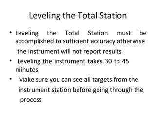
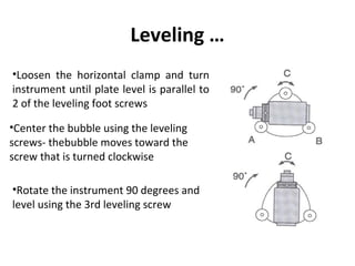
Leveling•Turn on the instrument by
pressing and holding the “on”
button (you should hear an
audible beep)
•The opening screen will be
the “MEAS” screen. Select
the
[Tilt] function
•Adjust the foot level screws
to exactly center the elctronic
“bubble
•Rotate the instrument 90
degrees and repeat](https://image.slidesharecdn.com/totalstation-180719161337/85/Total-station-22-320.jpg)


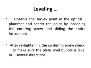
![Measurement of Target Height
•Set the Target Height from “MEAS” > “Menu” >
“Coordinate” > “Station Orientation” > “Station
Coordinate”
•Set the target height to the measured height of
the mirror target. You do not have to fill out the
other fields for a REM measurement
•Press “ESC” to return to the “MEAS” menu.
• Select the “MEAS” > “Menu” > “REM”, sight the
mirror target, press [OBS] to measure “S”, then
[STOP]
•Sight the object above the target for height
Measurement
• Select [REM] and then [STOP]](https://image.slidesharecdn.com/totalstation-180719161337/85/Total-station-25-320.jpg)

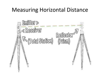


![Phase Shift Method
Thus, the distance(D) between the stations is D=(1/2)
[n+Δφ/360°]Xλ,where n is the integral number of
wavelength,λ in the double path.](https://image.slidesharecdn.com/totalstation-180719161337/85/Total-station-34-320.jpg)


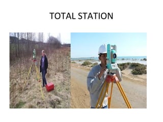
This document provides information about total station surveying equipment. It describes how a total station uses an integrated electronic theodolite, EDM, and microprocessor to automatically measure, reduce, display, and store surveying data in digital format. It also discusses accessories like prisms and tripods used with total stations. The document covers topics like robotic total stations, leveling the instrument, distance measurement techniques, and measuring horizontal distance, elevation, and slope distance with a total station.


