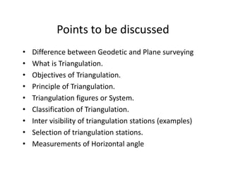
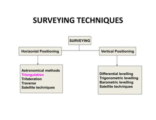
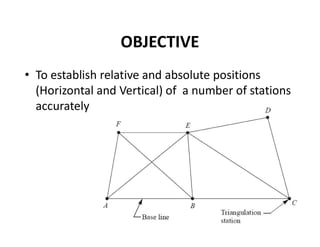
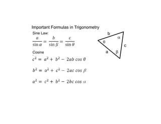
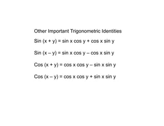
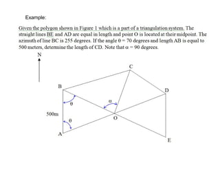
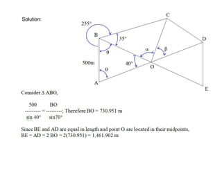
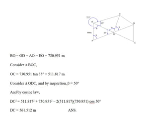
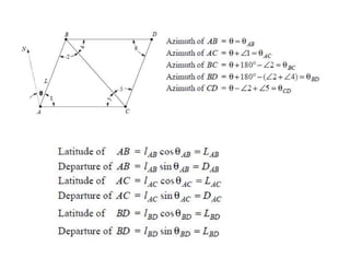
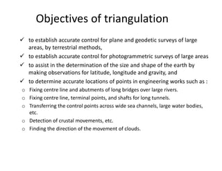
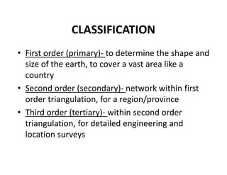
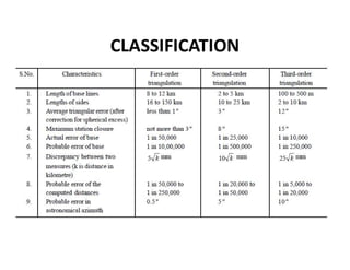
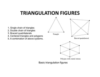
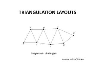
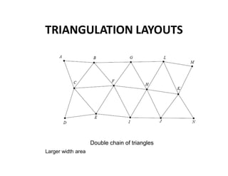
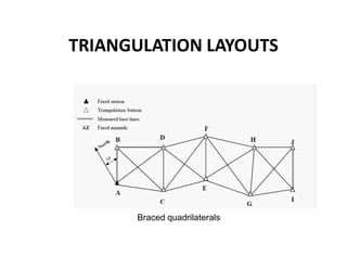
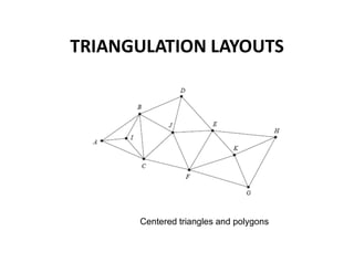
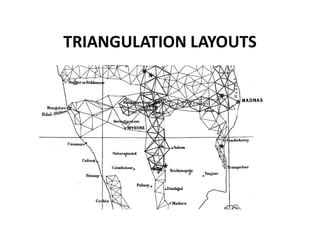
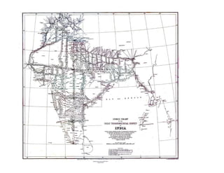
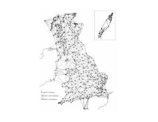
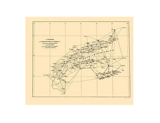
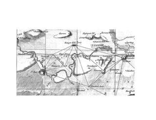
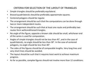
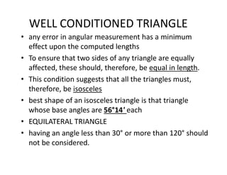
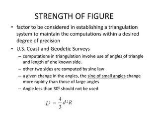
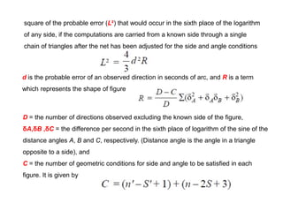
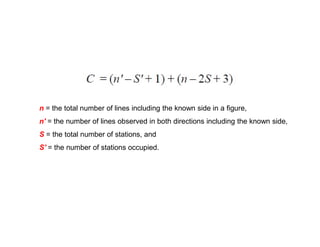
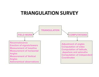
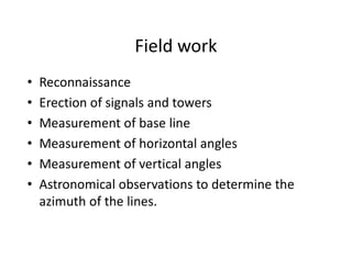
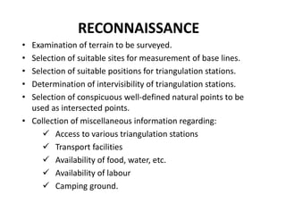
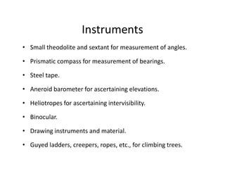
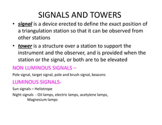
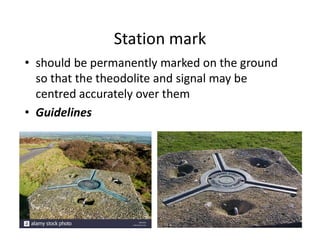
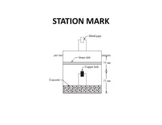
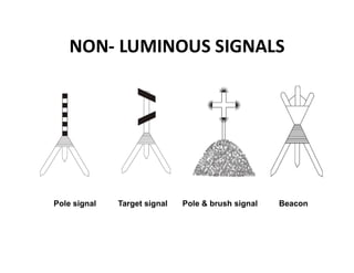
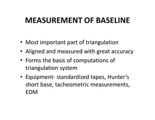
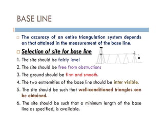
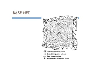
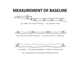
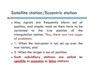
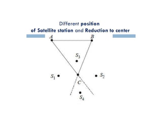
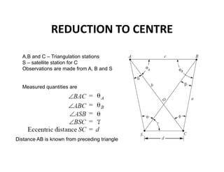
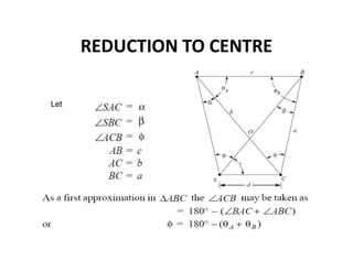
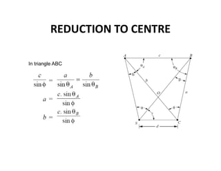
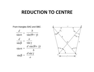
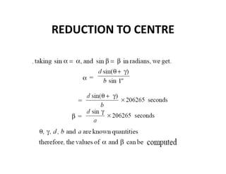
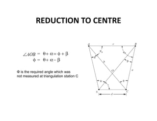
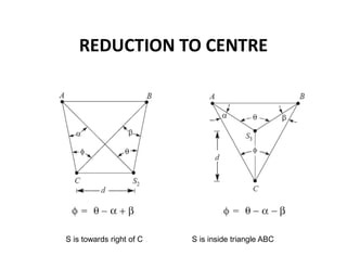
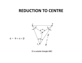
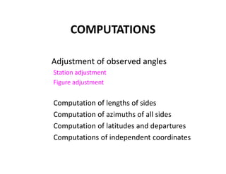
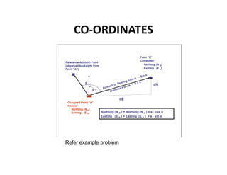
SlideShare a Scribd company logo
Geodetic Surveying and
Theory of Errors
Geodetic Surveying: Principle and Classification of triangulation system, Selection of base
line and stations, Orders of triangulation, Triangulation figures, Reduction to Centre,
Selection and marking of stations
Theory of Errors: Introduction, types of errors, definitions, laws of accidental errors, laws
of weights, theory of least squares, rules for giving weights and distribution of errors to
the field observations, determination of the most probable values of quantities.
Points to be discussed
• Difference between Geodetic and Plane surveying
• What is Triangulation.
• Objectives of Triangulation.
• Principle of Triangulation.
• Triangulation figures or System.
• Classification of Triangulation.
• Inter visibility of triangulation stations (examples)
• Selection of triangulation stations.
• Measurements of Horizontal angle
SURVEYING TECHNIQUES
SURVEYING
Horizontal Positioning Vertical Positioning
Astronomical methods
Triangulation
Trilateration
Traverse
Satellite techniques
Differential levelling
Trigonometric levelling
Barometric levelling
Satellite techniques
Triangulation
• Method of determining distance based on
the principles of geometry
• A distant object is sighted from two well-
separated locations
• The distancebetween the two locations
and the angle between the line joining
them and the line to the distant object
TRIANGULATION
• Utilizes geometric figures composed of
triangles.
• Horizontal angles and a limited no. of sides
(base lines) are measured
• By using angles and base line lengths, triangles
are solved trigonometrically and the positions
of stations (vertices) are calculated
OBJECTIVE
• To establish relative and absolute positions
(Horizontal and Vertical) of a number of stations
accurately
Important Formulas in Trigonometry



c
b
a
Sine Law:
Cosine
Law:
Other Important Trigonometric Identities
Sin (x + y) = sin x cos y + cos x sin y
Sin (x – y) = sin x cos y – cos x sin y
Cos (x + y) = cos x cos y – sin x sin y
Cos (x – y) = cos x cos y + sin x sin y
Example:
Solution:
Objectives of triangulation
 to establish accurate control for plane and geodetic surveys of large
areas, by terrestrial methods,
 to establish accurate control for photogrammetric surveys of large areas
 to assist in the determination of the size and shape of the earth by
making observations for latitude, longitude and gravity, and
 to determine accurate locations of points in engineering works such as :
o Fixing centre line and abutments of long bridges over large rivers.
o Fixing centre line, terminal points, and shafts for long tunnels.
o Transferring the control points across wide sea channels, large water bodies,
etc.
o Detection of crustal movements, etc.
o Finding the direction of the movement of clouds.
CLASSIFICATION
• First order (primary)- to determine the shape and
size of the earth, to cover a vast area like a
country
• Second order (secondary)- network within first
order triangulation, for a region/province
• Third order (tertiary)- within second order
triangulation, for detailed engineering and
location surveys
CLASSIFICATION
TRIANGULATION FIGURES
Basic triangulation figures
1. Single chain of triangles
2. Double chain of triangles
3. Braced quadrilaterals
4. Centered triangles and polygons
5. A combination of above systems.
TRIANGULATION LAYOUTS
Single chain of triangles
narrow strip of terrain
TRIANGULATION LAYOUTS
Double chain of triangles
Larger width area
TRIANGULATION LAYOUTS
Braced quadrilaterals
TRIANGULATION LAYOUTS
Centered triangles and polygons
PRIMARY TRIANGULATION FOR
LARGE COUNTRIES
GRID IRON SYSTEM CENTRAL SYSTEM
For Primary Triangulation
TRIANGULATION LAYOUTS
CRITERIA FOR SELECTION OF THE LAYOUT OF TRIANGLES
• Simple triangles should be preferably equilateral.
• Braced quadrilaterals should be preferably approximate squares.
• Centered polygons should be regular.
• The arrangement should be such that the computations can be done through
two or more independent routes.
• The arrangement should be such that at least one route and preferably two
routes form wellconditioned triangles.
• No angle of the figure, opposite a known side should be small, whichever end
of the series is used for computation.
• Angles of simple triangles should not be less than 45°, and in the case of
quadrilaterals, no angle should be less than 30°. In the case of centered
polygons, no angle should be less than 40°.
• The sides of the figures should be of comparable lengths. Very long lines and
very short lines should be avoided.
• The layout should be such that it requires least work to achieve maximum
progress.
• As far as possible, complex figures should not involve more than 12 conditions.
WELL CONDITIONED TRIANGLE
• any error in angular measurement has a minimum
effect upon the computed lengths
• To ensure that two sides of any triangle are equally
affected, these should, therefore, be equal in length.
• This condition suggests that all the triangles must,
therefore, be isosceles
• best shape of an isosceles triangle is that triangle
whose base angles are 56°14' each
• EQUILATERAL TRIANGLE
• having an angle less than 30° or more than 120° should
not be considered.
STRENGTH OF FIGURE
• factor to be considered in establishing a triangulation
system to maintain the computations within a desired
degree of precision
• U.S. Coast and Geodetic Surveys
– computations in triangulation involve use of angles of triangle
and length of one known side.
– other two sides are computed by sine law
– a given change in the angles, the sine of small angles change
more rapidly than those of large angles
– Angle less than 300 should not be used
square of the probable error (L²) that would occur in the sixth place of the logarithm
of any side, if the computations are carried from a known side through a single
chain of triangles after the net has been adjusted for the side and angle conditions
d is the probable error of an observed direction in seconds of arc, and R is a term
which represents the shape of figure
D = the number of directions observed excluding the known side of the figure,
δA,δB ,δC = the difference per second in the sixth place of logarithm of the sine of the
distance angles A, B and C, respectively. (Distance angle is the angle in a triangle
opposite to a side), and
C = the number of geometric conditions for side and angle to be satisfied in each
figure. It is given by
n = the total number of lines including the known side in a figure,
n' = the number of lines observed in both directions including the known side,
S = the total number of stations, and
S' = the number of stations occupied.
TRIANGULATION SURVEY
TRIANGULATION
FIELD WORK COMPUTATIONS
Reconnaissance
Erection of signals/towers
Measurement of baseline
Measurement of horizontal
Angles
Measurement of Vertical
Angles
Astronomical observations
Adjustment of angles
Computation of sides
Computation of latitude,
departure and azimuths
Computation of independent
Coordinates
Field work
• Reconnaissance
• Erection of signals and towers
• Measurement of base line
• Measurement of horizontal angles
• Measurement of vertical angles
• Astronomical observations to determine the
azimuth of the lines.
RECONNAISSANCE
• Examination of terrain to be surveyed.
• Selection of suitable sites for measurement of base lines.
• Selection of suitable positions for triangulation stations.
• Determination of intervisibility of triangulation stations.
• Selection of conspicuous well-defined natural points to be
used as intersected points.
• Collection of miscellaneous information regarding:
 Access to various triangulation stations
 Transport facilities
 Availability of food, water, etc.
 Availability of labour
 Camping ground.
Instruments
• Small theodolite and sextant for measurement of angles.
• Prismatic compass for measurement of bearings.
• Steel tape.
• Aneroid barometer for ascertaining elevations.
• Heliotropes for ascertaining intervisibility.
• Binocular.
• Drawing instruments and material.
• Guyed ladders, creepers, ropes, etc., for climbing trees.
SIGNALS AND TOWERS
• signal is a device erected to define the exact position of
a triangulation station so that it can be observed from
other stations
• tower is a structure over a station to support the
instrument and the observer, and is provided when the
station or the signal, or both are to be elevated
NON LUMINOUS SIGNALS –
Pole signal, target signal, pole and brush signal, beacons
LUMINOUS SIGNALS-
Sun signals – Heliotrope
Night signals - Oil lamps, electric lamps, acetylene lamps,
Magnesium lamps
Criteria for selection of triangulation stations
• should be intervisible. For this purpose the station points should
be on the highest ground such as hill tops, house tops, etc.
• easily accessible with instruments.
• form well-conditioned triangles.
• located that the lengths of sights are neither too small nor too
long.
• at commanding positions so as to serve as control for subsidiary
triangulation, and for possible extension of the main triangulation
scheme.
• useful for providing intersected points and also for detail survey.
• In wooded country, the stations should be selected such that the
cost of clearing and cutting, and building towers, is minimum.
• Grazing line of sights should be avoided, and no line of sight
should pass over the industrial areas to avoid irregular
atmospheric refraction.
Station mark
• should be permanently marked on the ground
so that the theodolite and signal may be
centred accurately over them
• Guidelines
STATION MARK
NON- LUMINOUS SIGNALS
Pole signal Target signal Pole & brush signal Beacon
LUMINOUS SIGNALS
SUN SIGNALS- HELIOTROPE
LUMINOUS SIGNALS
NIGHT SIGNALS
TOWERS
Required in flat areas
to elevate instrument,
observer, reflectors
TOWERS
Bilby tower- construction Completed tower
TOWERS
Truck mounted observation tower Portable mast-for lights/reflectors
MEASUREMENT OF BASELINE
• Most important part of triangulation
• Aligned and measured with great accuracy
• Forms the basis of computations of
triangulation system
• Equipment- standardized tapes, Hunter’s
short base, tacheometric measurements,
EDM
MEASUREMENT OF BASELINE
MEASUREMENT OF HORIZONTAL
ANGLES
• Optical/digital theodolites for primary and
secondary triangulation
• Transit theodolites for tertiary triangulation
• Method of repetition in tertiary and
secondary triangulation
• Method of reiteration in primary
triangulation
DETERMINATION OF AZIMUTH OF A
LINE
• Azimuth/true bearing of any line from a station
(Laplace station) is determined
• Methods- observations to star, by hour angle of
star or Sun, observation to circumpolar star,
knowing the magnetic declination at the place
REDUCTION TO CENTRE
• To secure well conditioned triangles/
intervisibility, objects such as chimneys, towers,
are selected as triangulation stations
• These can be sighted from other stations, but it is
not possible to occupy these stations for taking
observations
• In such cases a satellite station is established and
observations are taken and later reduced to what
they would have been if the main station was
occupied
REDUCTION TO CENTRE
A,B and C – Triangulation stations
S – satellite station for C
Observations are made from A, B and S
Measured quantities are
Distance AB is known from preceding triangle
REDUCTION TO CENTRE
Let
REDUCTION TO CENTRE
In triangle ABC
REDUCTION TO CENTRE
From triangles SAC and SBC
REDUCTION TO CENTRE
REDUCTION TO CENTRE
Φ is the required angle which was
not measured at triangulation station C
REDUCTION TO CENTRE
S is towards right of C S is inside triangle ABC
REDUCTION TO CENTRE
S is outside triangle ABC
COMPUTATIONS
Adjustment of observed angles
Station adjustment
Figure adjustment
Computation of lengths of sides
Computation of azimuths of all sides
Computation of latitudes and departures
Computations of independent coordinates
CO-ORDINATES
Refer example problem
COMPUTING DEPARTURES &
LATITUDES
• Compute by: Dep = L sin  Lat = L cos 
• Where:  = azimuth L = length of line
East (+X)
F
G
Dep. FG = L sin
Lat. FG = L cos 
L
North (+Y)
COMPUTATION OF INDEPENDENT
COORDINATES
• Assuming the coordinates of one station, the
coordinates of other stations can be
computed

More Related Content

What's hot

Compass surveying
Compass surveyingCompass surveying
Compass surveying
Rakesh Verma
 
Curves and there application in Survey
Curves and there application in SurveyCurves and there application in Survey
Curves and there application in Survey
Lord1911
 
surveying- lecture notes for engineers
surveying- lecture notes for engineerssurveying- lecture notes for engineers
surveying- lecture notes for engineers
musadoto
 
Theodolite surveying
Theodolite surveying Theodolite surveying
Theodolite surveying
neharajpl
 
Theodolite angle measurement
Theodolite angle measurementTheodolite angle measurement
Theodolite angle measurement
Mujeeb Muji
 
Tacheometry ppt
Tacheometry pptTacheometry ppt
Tacheometry ppt
Vilas Nikam
 
Chain surveying.1
Chain surveying.1Chain surveying.1
Chain surveying.1
Decentumang
 
Control surveying
Control surveyingControl surveying
Control surveying
Prakash Kumar Sekar
 
Total Station surveying
Total Station surveyingTotal Station surveying
Total Station surveying
RAMPRASAD KUMAWAT
 
Trigonometric levelling
Trigonometric levellingTrigonometric levelling
Trigonometric levelling
Rajendra Prasad
 
tacheometric surveying
tacheometric surveyingtacheometric surveying
tacheometric surveying
Mujeeb Muji
 
Tacheometric surveying ppt
Tacheometric surveying pptTacheometric surveying ppt
Tacheometric surveying ppt
Naufil Sayyad
 
Plane Table Surveying PPt
Plane Table Surveying PPtPlane Table Surveying PPt
Plane Table Surveying PPt
mohit kumar panchal
 
tacheometry surveying
tacheometry surveyingtacheometry surveying
tacheometry surveying
Jayachandra Jitendra
 
Introduction to surveying, ranging and chaining
Introduction to surveying, ranging and chainingIntroduction to surveying, ranging and chaining
Introduction to surveying, ranging and chaining
Shital Navghare
 
Levelling in Surveying
Levelling in SurveyingLevelling in Surveying
Levelling in Surveying
RAHUL SINHA
 
EDM
EDMEDM
Classification of triangulation
Classification of triangulationClassification of triangulation
Classification of triangulation
Fayaz Ahamed A P
 
9. MORDAN SURVEYING INSTRUMENTS (SUR) 3140601 GTU
9. MORDAN SURVEYING INSTRUMENTS (SUR) 3140601 GTU9. MORDAN SURVEYING INSTRUMENTS (SUR) 3140601 GTU
9. MORDAN SURVEYING INSTRUMENTS (SUR) 3140601 GTU
VATSAL PATEL
 
traversing of survey
traversing of surveytraversing of survey
traversing of survey
Self-employed
 

What's hot (20)

Compass surveying
Compass surveyingCompass surveying
Compass surveying
 
Curves and there application in Survey
Curves and there application in SurveyCurves and there application in Survey
Curves and there application in Survey
 
surveying- lecture notes for engineers
surveying- lecture notes for engineerssurveying- lecture notes for engineers
surveying- lecture notes for engineers
 
Theodolite surveying
Theodolite surveying Theodolite surveying
Theodolite surveying
 
Theodolite angle measurement
Theodolite angle measurementTheodolite angle measurement
Theodolite angle measurement
 
Tacheometry ppt
Tacheometry pptTacheometry ppt
Tacheometry ppt
 
Chain surveying.1
Chain surveying.1Chain surveying.1
Chain surveying.1
 
Control surveying
Control surveyingControl surveying
Control surveying
 
Total Station surveying
Total Station surveyingTotal Station surveying
Total Station surveying
 
Trigonometric levelling
Trigonometric levellingTrigonometric levelling
Trigonometric levelling
 
tacheometric surveying
tacheometric surveyingtacheometric surveying
tacheometric surveying
 
Tacheometric surveying ppt
Tacheometric surveying pptTacheometric surveying ppt
Tacheometric surveying ppt
 
Plane Table Surveying PPt
Plane Table Surveying PPtPlane Table Surveying PPt
Plane Table Surveying PPt
 
tacheometry surveying
tacheometry surveyingtacheometry surveying
tacheometry surveying
 
Introduction to surveying, ranging and chaining
Introduction to surveying, ranging and chainingIntroduction to surveying, ranging and chaining
Introduction to surveying, ranging and chaining
 
Levelling in Surveying
Levelling in SurveyingLevelling in Surveying
Levelling in Surveying
 
EDM
EDMEDM
EDM
 
Classification of triangulation
Classification of triangulationClassification of triangulation
Classification of triangulation
 
9. MORDAN SURVEYING INSTRUMENTS (SUR) 3140601 GTU
9. MORDAN SURVEYING INSTRUMENTS (SUR) 3140601 GTU9. MORDAN SURVEYING INSTRUMENTS (SUR) 3140601 GTU
9. MORDAN SURVEYING INSTRUMENTS (SUR) 3140601 GTU
 
traversing of survey
traversing of surveytraversing of survey
traversing of survey
 

Similar to Triangulation survey

UNIT 1_Chapter 2_Adv Survey.pptx
UNIT 1_Chapter 2_Adv Survey.pptxUNIT 1_Chapter 2_Adv Survey.pptx
UNIT 1_Chapter 2_Adv Survey.pptx
Mrunmayee Manjari
 
7. GEODETIC SYRVEYING (SUR) 3140601 GTU
7. GEODETIC SYRVEYING (SUR) 3140601 GTU7. GEODETIC SYRVEYING (SUR) 3140601 GTU
7. GEODETIC SYRVEYING (SUR) 3140601 GTU
VATSAL PATEL
 
DEFINITIONS, PRINCIPLES AND CHAIN SURVEYING
DEFINITIONS, PRINCIPLES AND CHAIN SURVEYINGDEFINITIONS, PRINCIPLES AND CHAIN SURVEYING
DEFINITIONS, PRINCIPLES AND CHAIN SURVEYING
Kamal B
 
Module-I SURVEYING-I [BTCVC304]
Module-I SURVEYING-I [BTCVC304]Module-I SURVEYING-I [BTCVC304]
Module-I SURVEYING-I [BTCVC304]
Dr. BASWESHWAR JIRWANKAR
 
1.5_Basic Engineering_Day 7.pptx
1.5_Basic Engineering_Day 7.pptx1.5_Basic Engineering_Day 7.pptx
1.5_Basic Engineering_Day 7.pptx
Janak82
 
Chain Surveying 2020.ppt
 Chain Surveying 2020.ppt Chain Surveying 2020.ppt
Chain Surveying 2020.ppt
AsadKhan606012
 
Chain surveying and offset
Chain surveying and offsetChain surveying and offset
Chain surveying and offset
Mir Zafarullah
 
Triangulation survey (Basic Mine Surveying)_MI10412MI.pptx
Triangulation survey (Basic Mine Surveying)_MI10412MI.pptxTriangulation survey (Basic Mine Surveying)_MI10412MI.pptx
Triangulation survey (Basic Mine Surveying)_MI10412MI.pptx
Dr Romil Mishra
 
Fundamentals of surveying
Fundamentals of surveyingFundamentals of surveying
Fundamentals of surveying
SimonReuben2
 
Surveying and levelling
Surveying and levellingSurveying and levelling
Surveying and levelling
Parimal Jha
 
Contouring
ContouringContouring
Contouring
GAURAV. H .TANDON
 
Triangulation and Trilateration
Triangulation and TrilaterationTriangulation and Trilateration
Triangulation and Trilateration
Pramesh Hada
 
1. Intro to Surveying.pdf
1. Intro to Surveying.pdf1. Intro to Surveying.pdf
1. Intro to Surveying.pdf
DivyaPriya700213
 
surveyf tururu ururtu65 6ru5uu56 686585 868
surveyf tururu ururtu65 6ru5uu56 686585 868surveyf tururu ururtu65 6ru5uu56 686585 868
surveyf tururu ururtu65 6ru5uu56 686585 868
RahulSinghParihar18
 
fundamentals_of_surveying (2).pdf
fundamentals_of_surveying (2).pdffundamentals_of_surveying (2).pdf
fundamentals_of_surveying (2).pdf
sandipanpaul16
 
Basic Civil and Mechanical Engineering
Basic Civil and Mechanical EngineeringBasic Civil and Mechanical Engineering
Basic Civil and Mechanical Engineering
PAAVAI ENGINEERING COLLEGE
 
handbook of civil engineering
handbook of civil engineeringhandbook of civil engineering
handbook of civil engineering
Ashok Narisetti
 
Diploma(civil) sem i boce_unit 2_ elementary surveying a
Diploma(civil) sem i boce_unit 2_ elementary surveying aDiploma(civil) sem i boce_unit 2_ elementary surveying a
Diploma(civil) sem i boce_unit 2_ elementary surveying a
Rai University
 

Similar to Triangulation survey (20)

UNIT 1_Chapter 2_Adv Survey.pptx
UNIT 1_Chapter 2_Adv Survey.pptxUNIT 1_Chapter 2_Adv Survey.pptx
UNIT 1_Chapter 2_Adv Survey.pptx
 
7. GEODETIC SYRVEYING (SUR) 3140601 GTU
7. GEODETIC SYRVEYING (SUR) 3140601 GTU7. GEODETIC SYRVEYING (SUR) 3140601 GTU
7. GEODETIC SYRVEYING (SUR) 3140601 GTU
 
DEFINITIONS, PRINCIPLES AND CHAIN SURVEYING
DEFINITIONS, PRINCIPLES AND CHAIN SURVEYINGDEFINITIONS, PRINCIPLES AND CHAIN SURVEYING
DEFINITIONS, PRINCIPLES AND CHAIN SURVEYING
 
Module-I SURVEYING-I [BTCVC304]
Module-I SURVEYING-I [BTCVC304]Module-I SURVEYING-I [BTCVC304]
Module-I SURVEYING-I [BTCVC304]
 
1.5_Basic Engineering_Day 7.pptx
1.5_Basic Engineering_Day 7.pptx1.5_Basic Engineering_Day 7.pptx
1.5_Basic Engineering_Day 7.pptx
 
Chain Surveying 2020.ppt
 Chain Surveying 2020.ppt Chain Surveying 2020.ppt
Chain Surveying 2020.ppt
 
Chain surveying and offset
Chain surveying and offsetChain surveying and offset
Chain surveying and offset
 
Triangulation survey (Basic Mine Surveying)_MI10412MI.pptx
Triangulation survey (Basic Mine Surveying)_MI10412MI.pptxTriangulation survey (Basic Mine Surveying)_MI10412MI.pptx
Triangulation survey (Basic Mine Surveying)_MI10412MI.pptx
 
Fundamentals of surveying
Fundamentals of surveyingFundamentals of surveying
Fundamentals of surveying
 
Surveying and levelling
Surveying and levellingSurveying and levelling
Surveying and levelling
 
30838893 chain-survey
30838893 chain-survey30838893 chain-survey
30838893 chain-survey
 
Contouring
ContouringContouring
Contouring
 
Triangulation and Trilateration
Triangulation and TrilaterationTriangulation and Trilateration
Triangulation and Trilateration
 
1. Intro to Surveying.pdf
1. Intro to Surveying.pdf1. Intro to Surveying.pdf
1. Intro to Surveying.pdf
 
Surveying
Surveying Surveying
Surveying
 
surveyf tururu ururtu65 6ru5uu56 686585 868
surveyf tururu ururtu65 6ru5uu56 686585 868surveyf tururu ururtu65 6ru5uu56 686585 868
surveyf tururu ururtu65 6ru5uu56 686585 868
 
fundamentals_of_surveying (2).pdf
fundamentals_of_surveying (2).pdffundamentals_of_surveying (2).pdf
fundamentals_of_surveying (2).pdf
 
Basic Civil and Mechanical Engineering
Basic Civil and Mechanical EngineeringBasic Civil and Mechanical Engineering
Basic Civil and Mechanical Engineering
 
handbook of civil engineering
handbook of civil engineeringhandbook of civil engineering
handbook of civil engineering
 
Diploma(civil) sem i boce_unit 2_ elementary surveying a
Diploma(civil) sem i boce_unit 2_ elementary surveying aDiploma(civil) sem i boce_unit 2_ elementary surveying a
Diploma(civil) sem i boce_unit 2_ elementary surveying a
 

Recently uploaded

The Benefits and Techniques of Trenchless Pipe Repair.pdf
The Benefits and Techniques of Trenchless Pipe Repair.pdfThe Benefits and Techniques of Trenchless Pipe Repair.pdf
The Benefits and Techniques of Trenchless Pipe Repair.pdf
Pipe Restoration Solutions
 
AKS UNIVERSITY Satna Final Year Project By OM Hardaha.pdf
AKS UNIVERSITY Satna Final Year Project By OM Hardaha.pdfAKS UNIVERSITY Satna Final Year Project By OM Hardaha.pdf
AKS UNIVERSITY Satna Final Year Project By OM Hardaha.pdf
SamSarthak3
 
road safety engineering r s e unit 3.pdf
road safety engineering  r s e unit 3.pdfroad safety engineering  r s e unit 3.pdf
road safety engineering r s e unit 3.pdf
VENKATESHvenky89705
 
Nuclear Power Economics and Structuring 2024
Nuclear Power Economics and Structuring 2024Nuclear Power Economics and Structuring 2024
Nuclear Power Economics and Structuring 2024
Massimo Talia
 
Forklift Classes Overview by Intella Parts
Forklift Classes Overview by Intella PartsForklift Classes Overview by Intella Parts
Forklift Classes Overview by Intella Parts
Intella Parts
 
WATER CRISIS and its solutions-pptx 1234
WATER CRISIS and its solutions-pptx 1234WATER CRISIS and its solutions-pptx 1234
WATER CRISIS and its solutions-pptx 1234
AafreenAbuthahir2
 
Democratizing Fuzzing at Scale by Abhishek Arya
Democratizing Fuzzing at Scale by Abhishek AryaDemocratizing Fuzzing at Scale by Abhishek Arya
Democratizing Fuzzing at Scale by Abhishek Arya
abh.arya
 
The role of big data in decision making.
The role of big data in decision making.The role of big data in decision making.
The role of big data in decision making.
ankuprajapati0525
 
addressing modes in computer architecture
addressing modes  in computer architectureaddressing modes  in computer architecture
addressing modes in computer architecture
ShahidSultan24
 
在线办理(ANU毕业证书)澳洲国立大学毕业证录取通知书一模一样
在线办理(ANU毕业证书)澳洲国立大学毕业证录取通知书一模一样在线办理(ANU毕业证书)澳洲国立大学毕业证录取通知书一模一样
在线办理(ANU毕业证书)澳洲国立大学毕业证录取通知书一模一样
obonagu
 
H.Seo, ICLR 2024, MLILAB, KAIST AI.pdf
H.Seo,  ICLR 2024, MLILAB,  KAIST AI.pdfH.Seo,  ICLR 2024, MLILAB,  KAIST AI.pdf
H.Seo, ICLR 2024, MLILAB, KAIST AI.pdf
MLILAB
 
Gen AI Study Jams _ For the GDSC Leads in India.pdf
Gen AI Study Jams _ For the GDSC Leads in India.pdfGen AI Study Jams _ For the GDSC Leads in India.pdf
Gen AI Study Jams _ For the GDSC Leads in India.pdf
gdsczhcet
 
NO1 Uk best vashikaran specialist in delhi vashikaran baba near me online vas...
NO1 Uk best vashikaran specialist in delhi vashikaran baba near me online vas...NO1 Uk best vashikaran specialist in delhi vashikaran baba near me online vas...
NO1 Uk best vashikaran specialist in delhi vashikaran baba near me online vas...
Amil Baba Dawood bangali
 
Water Industry Process Automation and Control Monthly - May 2024.pdf
Water Industry Process Automation and Control Monthly - May 2024.pdfWater Industry Process Automation and Control Monthly - May 2024.pdf
Water Industry Process Automation and Control Monthly - May 2024.pdf
Water Industry Process Automation & Control
 
weather web application report.pdf
weather web application report.pdfweather web application report.pdf
weather web application report.pdf
Pratik Pawar
 
Planning Of Procurement o different goods and services
Planning Of Procurement o different goods and servicesPlanning Of Procurement o different goods and services
Planning Of Procurement o different goods and services
JoytuBarua2
 
Sachpazis:Terzaghi Bearing Capacity Estimation in simple terms with Calculati...
Sachpazis:Terzaghi Bearing Capacity Estimation in simple terms with Calculati...Sachpazis:Terzaghi Bearing Capacity Estimation in simple terms with Calculati...
Sachpazis:Terzaghi Bearing Capacity Estimation in simple terms with Calculati...
Dr.Costas Sachpazis
 
Quality defects in TMT Bars, Possible causes and Potential Solutions.
Quality defects in TMT Bars, Possible causes and Potential Solutions.Quality defects in TMT Bars, Possible causes and Potential Solutions.
Quality defects in TMT Bars, Possible causes and Potential Solutions.
PrashantGoswami42
 
Event Management System Vb Net Project Report.pdf
Event Management System Vb Net  Project Report.pdfEvent Management System Vb Net  Project Report.pdf
Event Management System Vb Net Project Report.pdf
Kamal Acharya
 
TECHNICAL TRAINING MANUAL GENERAL FAMILIARIZATION COURSE
TECHNICAL TRAINING MANUAL   GENERAL FAMILIARIZATION COURSETECHNICAL TRAINING MANUAL   GENERAL FAMILIARIZATION COURSE
TECHNICAL TRAINING MANUAL GENERAL FAMILIARIZATION COURSE
DuvanRamosGarzon1
 

Recently uploaded (20)

The Benefits and Techniques of Trenchless Pipe Repair.pdf
The Benefits and Techniques of Trenchless Pipe Repair.pdfThe Benefits and Techniques of Trenchless Pipe Repair.pdf
The Benefits and Techniques of Trenchless Pipe Repair.pdf
 
AKS UNIVERSITY Satna Final Year Project By OM Hardaha.pdf
AKS UNIVERSITY Satna Final Year Project By OM Hardaha.pdfAKS UNIVERSITY Satna Final Year Project By OM Hardaha.pdf
AKS UNIVERSITY Satna Final Year Project By OM Hardaha.pdf
 
road safety engineering r s e unit 3.pdf
road safety engineering  r s e unit 3.pdfroad safety engineering  r s e unit 3.pdf
road safety engineering r s e unit 3.pdf
 
Nuclear Power Economics and Structuring 2024
Nuclear Power Economics and Structuring 2024Nuclear Power Economics and Structuring 2024
Nuclear Power Economics and Structuring 2024
 
Forklift Classes Overview by Intella Parts
Forklift Classes Overview by Intella PartsForklift Classes Overview by Intella Parts
Forklift Classes Overview by Intella Parts
 
WATER CRISIS and its solutions-pptx 1234
WATER CRISIS and its solutions-pptx 1234WATER CRISIS and its solutions-pptx 1234
WATER CRISIS and its solutions-pptx 1234
 
Democratizing Fuzzing at Scale by Abhishek Arya
Democratizing Fuzzing at Scale by Abhishek AryaDemocratizing Fuzzing at Scale by Abhishek Arya
Democratizing Fuzzing at Scale by Abhishek Arya
 
The role of big data in decision making.
The role of big data in decision making.The role of big data in decision making.
The role of big data in decision making.
 
addressing modes in computer architecture
addressing modes  in computer architectureaddressing modes  in computer architecture
addressing modes in computer architecture
 
在线办理(ANU毕业证书)澳洲国立大学毕业证录取通知书一模一样
在线办理(ANU毕业证书)澳洲国立大学毕业证录取通知书一模一样在线办理(ANU毕业证书)澳洲国立大学毕业证录取通知书一模一样
在线办理(ANU毕业证书)澳洲国立大学毕业证录取通知书一模一样
 
H.Seo, ICLR 2024, MLILAB, KAIST AI.pdf
H.Seo,  ICLR 2024, MLILAB,  KAIST AI.pdfH.Seo,  ICLR 2024, MLILAB,  KAIST AI.pdf
H.Seo, ICLR 2024, MLILAB, KAIST AI.pdf
 
Gen AI Study Jams _ For the GDSC Leads in India.pdf
Gen AI Study Jams _ For the GDSC Leads in India.pdfGen AI Study Jams _ For the GDSC Leads in India.pdf
Gen AI Study Jams _ For the GDSC Leads in India.pdf
 
NO1 Uk best vashikaran specialist in delhi vashikaran baba near me online vas...
NO1 Uk best vashikaran specialist in delhi vashikaran baba near me online vas...NO1 Uk best vashikaran specialist in delhi vashikaran baba near me online vas...
NO1 Uk best vashikaran specialist in delhi vashikaran baba near me online vas...
 
Water Industry Process Automation and Control Monthly - May 2024.pdf
Water Industry Process Automation and Control Monthly - May 2024.pdfWater Industry Process Automation and Control Monthly - May 2024.pdf
Water Industry Process Automation and Control Monthly - May 2024.pdf
 
weather web application report.pdf
weather web application report.pdfweather web application report.pdf
weather web application report.pdf
 
Planning Of Procurement o different goods and services
Planning Of Procurement o different goods and servicesPlanning Of Procurement o different goods and services
Planning Of Procurement o different goods and services
 
Sachpazis:Terzaghi Bearing Capacity Estimation in simple terms with Calculati...
Sachpazis:Terzaghi Bearing Capacity Estimation in simple terms with Calculati...Sachpazis:Terzaghi Bearing Capacity Estimation in simple terms with Calculati...
Sachpazis:Terzaghi Bearing Capacity Estimation in simple terms with Calculati...
 
Quality defects in TMT Bars, Possible causes and Potential Solutions.
Quality defects in TMT Bars, Possible causes and Potential Solutions.Quality defects in TMT Bars, Possible causes and Potential Solutions.
Quality defects in TMT Bars, Possible causes and Potential Solutions.
 
Event Management System Vb Net Project Report.pdf
Event Management System Vb Net  Project Report.pdfEvent Management System Vb Net  Project Report.pdf
Event Management System Vb Net Project Report.pdf
 
TECHNICAL TRAINING MANUAL GENERAL FAMILIARIZATION COURSE
TECHNICAL TRAINING MANUAL   GENERAL FAMILIARIZATION COURSETECHNICAL TRAINING MANUAL   GENERAL FAMILIARIZATION COURSE
TECHNICAL TRAINING MANUAL GENERAL FAMILIARIZATION COURSE
 

Triangulation survey

  • 1. Geodetic Surveying and Theory of Errors Geodetic Surveying: Principle and Classification of triangulation system, Selection of base line and stations, Orders of triangulation, Triangulation figures, Reduction to Centre, Selection and marking of stations Theory of Errors: Introduction, types of errors, definitions, laws of accidental errors, laws of weights, theory of least squares, rules for giving weights and distribution of errors to the field observations, determination of the most probable values of quantities.
  • 2. Points to be discussed • Difference between Geodetic and Plane surveying • What is Triangulation. • Objectives of Triangulation. • Principle of Triangulation. • Triangulation figures or System. • Classification of Triangulation. • Inter visibility of triangulation stations (examples) • Selection of triangulation stations. • Measurements of Horizontal angle
  • 3. SURVEYING TECHNIQUES SURVEYING Horizontal Positioning Vertical Positioning Astronomical methods Triangulation Trilateration Traverse Satellite techniques Differential levelling Trigonometric levelling Barometric levelling Satellite techniques
  • 4. Triangulation • Method of determining distance based on the principles of geometry • A distant object is sighted from two well- separated locations • The distancebetween the two locations and the angle between the line joining them and the line to the distant object
  • 5. TRIANGULATION • Utilizes geometric figures composed of triangles. • Horizontal angles and a limited no. of sides (base lines) are measured • By using angles and base line lengths, triangles are solved trigonometrically and the positions of stations (vertices) are calculated
  • 6. OBJECTIVE • To establish relative and absolute positions (Horizontal and Vertical) of a number of stations accurately
  • 7. Important Formulas in Trigonometry    c b a Sine Law: Cosine Law:
  • 8. Other Important Trigonometric Identities Sin (x + y) = sin x cos y + cos x sin y Sin (x – y) = sin x cos y – cos x sin y Cos (x + y) = cos x cos y – sin x sin y Cos (x – y) = cos x cos y + sin x sin y
  • 11.
  • 12.
  • 13. Objectives of triangulation  to establish accurate control for plane and geodetic surveys of large areas, by terrestrial methods,  to establish accurate control for photogrammetric surveys of large areas  to assist in the determination of the size and shape of the earth by making observations for latitude, longitude and gravity, and  to determine accurate locations of points in engineering works such as : o Fixing centre line and abutments of long bridges over large rivers. o Fixing centre line, terminal points, and shafts for long tunnels. o Transferring the control points across wide sea channels, large water bodies, etc. o Detection of crustal movements, etc. o Finding the direction of the movement of clouds.
  • 14. CLASSIFICATION • First order (primary)- to determine the shape and size of the earth, to cover a vast area like a country • Second order (secondary)- network within first order triangulation, for a region/province • Third order (tertiary)- within second order triangulation, for detailed engineering and location surveys
  • 16. TRIANGULATION FIGURES Basic triangulation figures 1. Single chain of triangles 2. Double chain of triangles 3. Braced quadrilaterals 4. Centered triangles and polygons 5. A combination of above systems.
  • 17. TRIANGULATION LAYOUTS Single chain of triangles narrow strip of terrain
  • 18. TRIANGULATION LAYOUTS Double chain of triangles Larger width area
  • 21. PRIMARY TRIANGULATION FOR LARGE COUNTRIES GRID IRON SYSTEM CENTRAL SYSTEM For Primary Triangulation
  • 23.
  • 24.
  • 25.
  • 26.
  • 27. CRITERIA FOR SELECTION OF THE LAYOUT OF TRIANGLES • Simple triangles should be preferably equilateral. • Braced quadrilaterals should be preferably approximate squares. • Centered polygons should be regular. • The arrangement should be such that the computations can be done through two or more independent routes. • The arrangement should be such that at least one route and preferably two routes form wellconditioned triangles. • No angle of the figure, opposite a known side should be small, whichever end of the series is used for computation. • Angles of simple triangles should not be less than 45°, and in the case of quadrilaterals, no angle should be less than 30°. In the case of centered polygons, no angle should be less than 40°. • The sides of the figures should be of comparable lengths. Very long lines and very short lines should be avoided. • The layout should be such that it requires least work to achieve maximum progress. • As far as possible, complex figures should not involve more than 12 conditions.
  • 28. WELL CONDITIONED TRIANGLE • any error in angular measurement has a minimum effect upon the computed lengths • To ensure that two sides of any triangle are equally affected, these should, therefore, be equal in length. • This condition suggests that all the triangles must, therefore, be isosceles • best shape of an isosceles triangle is that triangle whose base angles are 56°14' each • EQUILATERAL TRIANGLE • having an angle less than 30° or more than 120° should not be considered.
  • 29. STRENGTH OF FIGURE • factor to be considered in establishing a triangulation system to maintain the computations within a desired degree of precision • U.S. Coast and Geodetic Surveys – computations in triangulation involve use of angles of triangle and length of one known side. – other two sides are computed by sine law – a given change in the angles, the sine of small angles change more rapidly than those of large angles – Angle less than 300 should not be used
  • 30. square of the probable error (L²) that would occur in the sixth place of the logarithm of any side, if the computations are carried from a known side through a single chain of triangles after the net has been adjusted for the side and angle conditions d is the probable error of an observed direction in seconds of arc, and R is a term which represents the shape of figure D = the number of directions observed excluding the known side of the figure, δA,δB ,δC = the difference per second in the sixth place of logarithm of the sine of the distance angles A, B and C, respectively. (Distance angle is the angle in a triangle opposite to a side), and C = the number of geometric conditions for side and angle to be satisfied in each figure. It is given by
  • 31. n = the total number of lines including the known side in a figure, n' = the number of lines observed in both directions including the known side, S = the total number of stations, and S' = the number of stations occupied.
  • 32. TRIANGULATION SURVEY TRIANGULATION FIELD WORK COMPUTATIONS Reconnaissance Erection of signals/towers Measurement of baseline Measurement of horizontal Angles Measurement of Vertical Angles Astronomical observations Adjustment of angles Computation of sides Computation of latitude, departure and azimuths Computation of independent Coordinates
  • 33. Field work • Reconnaissance • Erection of signals and towers • Measurement of base line • Measurement of horizontal angles • Measurement of vertical angles • Astronomical observations to determine the azimuth of the lines.
  • 34. RECONNAISSANCE • Examination of terrain to be surveyed. • Selection of suitable sites for measurement of base lines. • Selection of suitable positions for triangulation stations. • Determination of intervisibility of triangulation stations. • Selection of conspicuous well-defined natural points to be used as intersected points. • Collection of miscellaneous information regarding:  Access to various triangulation stations  Transport facilities  Availability of food, water, etc.  Availability of labour  Camping ground.
  • 35. Instruments • Small theodolite and sextant for measurement of angles. • Prismatic compass for measurement of bearings. • Steel tape. • Aneroid barometer for ascertaining elevations. • Heliotropes for ascertaining intervisibility. • Binocular. • Drawing instruments and material. • Guyed ladders, creepers, ropes, etc., for climbing trees.
  • 36. SIGNALS AND TOWERS • signal is a device erected to define the exact position of a triangulation station so that it can be observed from other stations • tower is a structure over a station to support the instrument and the observer, and is provided when the station or the signal, or both are to be elevated NON LUMINOUS SIGNALS – Pole signal, target signal, pole and brush signal, beacons LUMINOUS SIGNALS- Sun signals – Heliotrope Night signals - Oil lamps, electric lamps, acetylene lamps, Magnesium lamps
  • 37. Criteria for selection of triangulation stations • should be intervisible. For this purpose the station points should be on the highest ground such as hill tops, house tops, etc. • easily accessible with instruments. • form well-conditioned triangles. • located that the lengths of sights are neither too small nor too long. • at commanding positions so as to serve as control for subsidiary triangulation, and for possible extension of the main triangulation scheme. • useful for providing intersected points and also for detail survey. • In wooded country, the stations should be selected such that the cost of clearing and cutting, and building towers, is minimum. • Grazing line of sights should be avoided, and no line of sight should pass over the industrial areas to avoid irregular atmospheric refraction.
  • 38. Station mark • should be permanently marked on the ground so that the theodolite and signal may be centred accurately over them • Guidelines
  • 40.
  • 41. NON- LUMINOUS SIGNALS Pole signal Target signal Pole & brush signal Beacon
  • 42.
  • 45. TOWERS Required in flat areas to elevate instrument, observer, reflectors
  • 47. TOWERS Truck mounted observation tower Portable mast-for lights/reflectors
  • 48.
  • 49.
  • 50.
  • 51.
  • 52.
  • 53.
  • 54.
  • 55.
  • 56. MEASUREMENT OF BASELINE • Most important part of triangulation • Aligned and measured with great accuracy • Forms the basis of computations of triangulation system • Equipment- standardized tapes, Hunter’s short base, tacheometric measurements, EDM
  • 57.
  • 58.
  • 60.
  • 61.
  • 62. MEASUREMENT OF HORIZONTAL ANGLES • Optical/digital theodolites for primary and secondary triangulation • Transit theodolites for tertiary triangulation • Method of repetition in tertiary and secondary triangulation • Method of reiteration in primary triangulation
  • 63. DETERMINATION OF AZIMUTH OF A LINE • Azimuth/true bearing of any line from a station (Laplace station) is determined • Methods- observations to star, by hour angle of star or Sun, observation to circumpolar star, knowing the magnetic declination at the place
  • 64. REDUCTION TO CENTRE • To secure well conditioned triangles/ intervisibility, objects such as chimneys, towers, are selected as triangulation stations • These can be sighted from other stations, but it is not possible to occupy these stations for taking observations • In such cases a satellite station is established and observations are taken and later reduced to what they would have been if the main station was occupied
  • 65.
  • 66.
  • 67.
  • 68. REDUCTION TO CENTRE A,B and C – Triangulation stations S – satellite station for C Observations are made from A, B and S Measured quantities are Distance AB is known from preceding triangle
  • 70. REDUCTION TO CENTRE In triangle ABC
  • 71. REDUCTION TO CENTRE From triangles SAC and SBC
  • 73. REDUCTION TO CENTRE Φ is the required angle which was not measured at triangulation station C
  • 74. REDUCTION TO CENTRE S is towards right of C S is inside triangle ABC
  • 75. REDUCTION TO CENTRE S is outside triangle ABC
  • 76. COMPUTATIONS Adjustment of observed angles Station adjustment Figure adjustment Computation of lengths of sides Computation of azimuths of all sides Computation of latitudes and departures Computations of independent coordinates
  • 78. COMPUTING DEPARTURES & LATITUDES • Compute by: Dep = L sin  Lat = L cos  • Where:  = azimuth L = length of line East (+X) F G Dep. FG = L sin Lat. FG = L cos  L North (+Y)
  • 79. COMPUTATION OF INDEPENDENT COORDINATES • Assuming the coordinates of one station, the coordinates of other stations can be computed