Downloaded 28 times

![5- To level the instrument correctly and easily, Turn the instrument
until the telescope is parallel to a linebetween levelling foot screws
Aand B, then tighten the horizontal clamp.
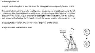
6-Set the tilt angle to 0° using foot
screws A and B for the X direction and
levelling screw C for the Y direction.
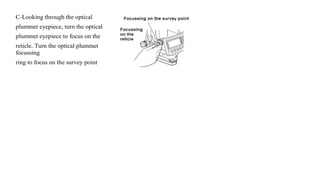
7- Loosen the centering screw slightly.
Looking through the optical plummet
eyepiece, slide the instrument over the
tripod head until the survey point is
exactly centered in the reticle. Retighten the centering screw securely.
8-Finally, When levelling is completed, press [OK]changes to the OBS
mode.](https://image.slidesharecdn.com/lecture1leveling-centering-tilting-func-totalstation-220910185020-70bd1986/85/lecture_-1-_-Leveling-Centering-Tilting-FUNC-total-station-8-320.jpg)
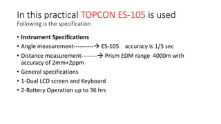
![Topcon ES-105 instrument includes three main pages as follows:
• Page 1:
• [MEAS] [SHV] [0SET] [COORD]
• Page 2:
• [MENU] [TILT] [H-SET] [EDM]
• Page 3:
• [MLM] [OFFSET] [TOPO] [S-O]](https://image.slidesharecdn.com/lecture1leveling-centering-tilting-func-totalstation-220910185020-70bd1986/85/lecture_-1-_-Leveling-Centering-Tilting-FUNC-total-station-13-320.jpg)
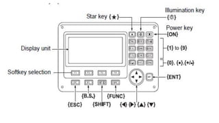
![The following functions can be allocated to the softkeys.
• [MEAS] : Distance measurement
• [SHV]: Switch between angle display and distance display
• [0SET]: Set horizontal angle to 0
• [COORD]: Coordinates measurement
• [REP]: Repetition measurement
• [MLM]: Missing line measurement
• [S-O]: Setting-out measurement
• [OFFSET] : Offset measurement
• [TOPO] :To TOPO menu
• [EDM]: Setting EDM
• [H-SET]: Set required horizontal angle
• [TILT]: Display tilt angle](https://image.slidesharecdn.com/lecture1leveling-centering-tilting-func-totalstation-220910185020-70bd1986/85/lecture_-1-_-Leveling-Centering-Tilting-FUNC-total-station-14-320.jpg)
![• [MENU]To Menu mode (Coordinates measurement, setting-out
measurement, offset measurement, repetition measurement, missing
line measurement, REM measurement, resection measurement,
surface area measurement, set-out line, set-out arc, point projection,
intersections, traverse](https://image.slidesharecdn.com/lecture1leveling-centering-tilting-func-totalstation-220910185020-70bd1986/85/lecture_-1-_-Leveling-Centering-Tilting-FUNC-total-station-15-320.jpg)
![the horizontal angle to a required value (Hz angle hold)
• You can reset horizontal angle to a required value and use this value to find the horizontal angle of a new target.
• PROCEDURE Entering the horizontal angle
• 1-Target the instrument to the prism.
• 2-Press [H-SET] on the second page of the BOS mode and select “Angle”.
• 3-Enter the angle you wish to set then press [OK]. Then press [REC] to set and record the horizontal angle.
• 4-Attempt to sight the second target. As the result, the horizontal angle from the second target to the value set as the
horizontal angle is displayed.](https://image.slidesharecdn.com/lecture1leveling-centering-tilting-func-totalstation-220910185020-70bd1986/85/lecture_-1-_-Leveling-Centering-Tilting-FUNC-total-station-16-320.jpg)
![DISTANCE MEASUREMENT
• 1-light the target
• 2-In the first page of OBS mode, press [MEAS] to start distance measurement.
• When measurement starts, EDM information (distance mode, prism constant correction value, atmospheric
correction factor) is represented by a flashing light.
• A short beep sound, and the measured distance data (SD),
• Vertical angle (ZA), and horizontal angle (HA-R) are displayed.
• 3-Press [STOP] to record distance measurement.
• NOTE:
• • Each time [SHV] is pressed, slope distance (SD), horizontal distance (HD) and height difference (VD) are
displayed alternately.](https://image.slidesharecdn.com/lecture1leveling-centering-tilting-func-totalstation-220910185020-70bd1986/85/lecture_-1-_-Leveling-Centering-Tilting-FUNC-total-station-17-320.jpg)

The document outlines the setup, leveling, and operational procedures for using a Topcon ES-105 total station in surveying, detailing the necessary equipment and the measurements to be taken. Key operational steps include centering, leveling, and performing angle and distance measurements, with specific instructions provided for using the instrument's functions. Specifications for the instrument are included, along with basic key operations and functions available on the device.


![Geotechnical Engineering-II [Lec #26: Slope Stability]](https://cdn.slidesharecdn.com/ss_thumbnails/26-181125070353-thumbnail.jpg?width=640&height=640&fit=bounds)


![Geotechnical Engineering-II [Lec #9+10: Westergaard Theory]](https://cdn.slidesharecdn.com/ss_thumbnails/9-181020124827-thumbnail.jpg?width=640&height=640&fit=bounds)


