The Surveying Lab Manual is designed for civil engineering students to gain practical knowledge and hands-on experience in surveying techniques. This manual covers fundamental and advanced topics including chain surveying, compass surveying, levelling and contouring, theodolite surveying, tachometric surveying, and EDM surveying. Students will also be introduced to modern methods such as Total Station surveying, GPS surveying, drone surveying, LiDAR surveying, and photogrammetry.
Through step-by-step surveying field procedures, learners will practice horizontal and vertical distance measurement, apply surveying instruments and accessories, and develop skills in survey plotting and mapping. Special emphasis is placed on survey data analysis and preparing detailed surveying reports. The manual includes practical exercises to bridge the gap between theoretical concepts and real-world applications, ensuring that students are well-prepared for professional surveying tasks in civil engineering projects.


![DEPARTMENT OF CIVIL ENGINEERING SURVEYING – II LAB MANUAL
24
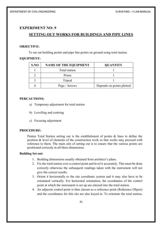
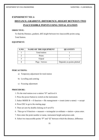
EXPERIMENT NO: 7
CURVE SETTING USING TOTAL STATION
OBJECTIVE:
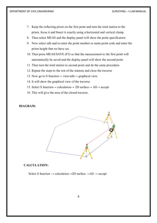
To determine angle/distance measurements to known points using total station.
EQUIPMENT:
S.NO NAME OF THE EQUIPMENT QUANTITY
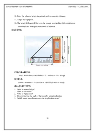
1 Total station 1
2 Prism 1
3 Tripod 1
4 Pegs / Arrows Depends on points plotted
PERCAUTIONS:
a) Temporary adjustment for total station
b) Levelling and centring
c) Focusing adjustment
PROCEDURE:
Simple Curve: A simple curve is a circular arc in the horizontal plane that has a central angle
of less than 180 degrees (PI radians). A simple curve starts at the PC (Point of Curvature), has
a CC (Circle Centre) and a PI (Point of Intersection for the tangents to the curve), and ends at
the PT (Point of Tangency, the ending point of the curve).
1. From the Power Topo Lite screen, press [F2] [CALC] to view CALCULATION screen.](https://image.slidesharecdn.com/2017-18surveyinglab2manual-250812080746-4e0a733e/85/2017-18-surveying-lab-2-manual-total-sta-27-320.jpg)
![DEPARTMENT OF CIVIL ENGINEERING SURVEYING – II LAB MANUAL
25
2. Select 1. COGO and press [ENT] to view the COGO screen.
3. Select the 1. INVERSE and press [ENT] to view INVERSE screen.
4. Start point input (Input the PN, Coordinates and PC of the Start point.)
5. Select 1. SP and press [ENT] to view SP screen.
6. [LIST] key All stored points can be displayed as follows by pressing [F2] [LIST]. Press
[F2] [LIST] to view POINT SELECTION FROM THE LIST screen.
7. Press [ENT] to open the SP input screen.
8. Input your desired Point Name by pressing keys, and press [ENT] to open the X
coordinate input screen.
9. Input your desired value by pressing each keys and press [ENT] to go Y coordinate.](https://image.slidesharecdn.com/2017-18surveyinglab2manual-250812080746-4e0a733e/85/2017-18-surveying-lab-2-manual-total-sta-28-320.jpg)
![DEPARTMENT OF CIVIL ENGINEERING SURVEYING – II LAB MANUAL
26
10. Press [ENT] to open the Y coordinate input screen and input.
11. Press [ENT] to open the Z coordinate input screen and input.
12. Press [ENT] to open the PC input screen and input.
13. End point coordinates input (Input the PN, Coordinates and PC of the End point.)
14. After PC input, EP screen is viewed.
15. Input the PN, X, Y, Z Coordinates and PC name of the End point.
16. Press [ENT] to view the RESULT OF INVERSE screen.
17. Another End Point Coordinates input the PN, X, Y, Z Coordinates and PC name of
another End point, and another inverse result can be performed.
18. A point Coordinates is calculated from a known point Coordinates and the Distance and
Horizontal angle of the Second point.](https://image.slidesharecdn.com/2017-18surveyinglab2manual-250812080746-4e0a733e/85/2017-18-surveying-lab-2-manual-total-sta-29-320.jpg)
![DEPARTMENT OF CIVIL ENGINEERING SURVEYING – II LAB MANUAL
27
19. Input: Coordinates of a known point, Distance and Horizontal angle of the Second point
Output: Coordinates of the Second point
20. From the Power Topo Lite screen, press [F2] [CALC] to view the CALCULATION
screen.
21. Select 1.COGO and press [ENT] to view the COGO screen.
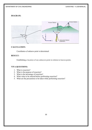
DIAGRAM:
CALCULATION:
From the Power Topo Lite screen, press [F2] [CALC] to view the CALCULATION screen.
RESULT:
Defining and setting of curve is done.
22. From the Power Topo Lite screen, press [F2] [CALC] to view the CALCULATION
screen.
VIVA QUESTIONS:
1. What is curve setting?
2. Where the curve setting method is applied in civil engineering constructions?
3. What are the programs you can find in COGO?
4. What are the various methods available for curve setting?
5. Give a list of various types of curves.](https://image.slidesharecdn.com/2017-18surveyinglab2manual-250812080746-4e0a733e/85/2017-18-surveying-lab-2-manual-total-sta-30-320.jpg)
![DEPARTMENT OF CIVIL ENGINEERING SURVEYING – II LAB MANUAL
29
1. Prior to resection enter survey markers as known points through the “MEM” menu.
2. From the “MEAS” menu select “[MENU]” > [RESEC].
3. The resection procedure requires that the known coordinates be defined first coordinates,
and in the order that they will be shot.
4. In the top right screen, the 1st point has been point defined and the 2-defined point is being
entered. You point is being entered. You can use [READ] to read in previously entered or
can use [READ] to read in previously entered or measured points measured point.
5. Press the “>” or “< “arrow to move to next or previous point.
6. When all points are entered select [MEAS].
7. The [MEAS] screen (right) displays the point being shot – in this example the 1st point.
8. Choose [DIST] if you are shooting to a mirror target, [ANGLE] if not.
9. Select [YES] to accept measurement, [NO] to re measurement, [NO] to re -shoot, [EDIT]
to change target height.
10. The [CALC] option will be displayed when the standard deviation of northing and easting
can be displayed.
11. Press [CALC] or [YES] on last point to display the calculated instrument coordinates and
the standard deviation of coordinates of easting ( easting ( σ E) and northing ( σN). Press
[OK] to finish Resection](https://image.slidesharecdn.com/2017-18surveyinglab2manual-250812080746-4e0a733e/85/2017-18-surveying-lab-2-manual-total-sta-32-320.jpg)