Download as PDF, PPTX

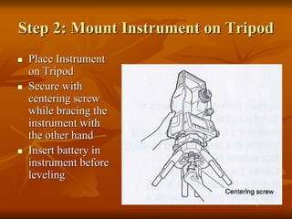

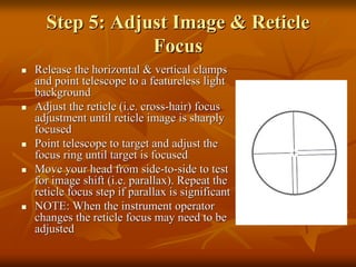
![Step 5: Electronically VerifyStep 5: Electronically Verify
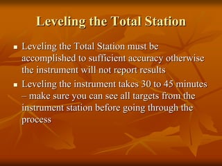
LevelingLeveling
Turn on the instrument byTurn on the instrument by
pressing and holding thepressing and holding the ““onon””
button (you should hear anbutton (you should hear an
audible beep)audible beep)
The opening screen will be theThe opening screen will be the
““MEASMEAS”” screen. Select thescreen. Select the
[Tilt] function[Tilt] function
Adjust the foot level screws toAdjust the foot level screws to
exactly center the electronicexactly center the electronic
““bubblebubble””
Rotate the instrument 90Rotate the instrument 90
degrees and repeatdegrees and repeat](https://image.slidesharecdn.com/totalstationsetupandoperation-150317145143-conversion-gate01/85/Sokkia-Total-station-setup-and-operation-14-320.jpg)
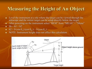
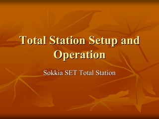
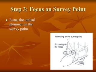
![Measurement of Target HeightMeasurement of Target Height
Set the Target Height fromSet the Target Height from ““MEASMEAS”” >> ““MenuMenu”” >>
““CoordinateCoordinate”” >> ““Station OrientationStation Orientation”” >> ““StationStation
CoordinateCoordinate””
Set the target height to the measured height of theSet the target height to the measured height of the
mirror target. You do not have to fill out the othermirror target. You do not have to fill out the other
fields for a REM measurementfields for a REM measurement
PressPress ““ESCESC”” to return to theto return to the ““MEASMEAS”” menumenu
Select theSelect the ““MEASMEAS”” >> ““MenuMenu”” >> ““REMREM””, sight the, sight the
mirror target, press [OBS] to measuremirror target, press [OBS] to measure ““SS””, then, then
[STOP][STOP]
Sight the object above the target for heightSight the object above the target for height
measurementmeasurement
Select [REM] and then [STOP]Select [REM] and then [STOP]](https://image.slidesharecdn.com/totalstationsetupandoperation-150317145143-conversion-gate01/85/Sokkia-Total-station-setup-and-operation-17-320.jpg)
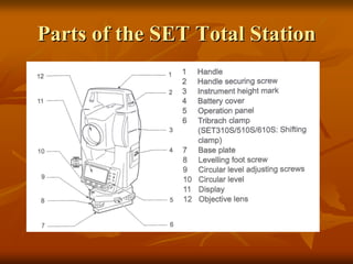
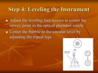
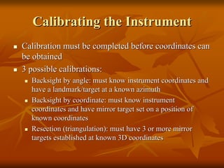
![REM Screen ResultsREM Screen Results
To reTo re--shoot theshoot the
mirror target use themirror target use the
[OBS] on the REM[OBS] on the REM
screenscreen](https://image.slidesharecdn.com/totalstationsetupandoperation-150317145143-conversion-gate01/85/Sokkia-Total-station-setup-and-operation-18-320.jpg)
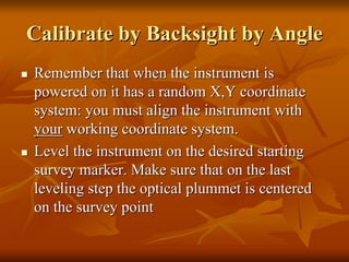
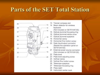
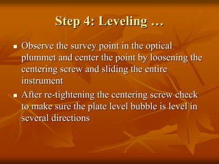
![BacksightBacksight by Angle continued..by Angle continued..
Measure the target height andMeasure the target height and
instrument heightinstrument height
Select [COORD] from the MEAS menuSelect [COORD] from the MEAS menu
SelectSelect ““StnStn. Orientation. Orientation”” and thenand then ““StnStn..
CoordinateCoordinate””
Edit theEdit the ““N0N0””,, ““E0E0””, and, and ““Z0Z0”” fields tofields to
appropriate values (i.e. northing,appropriate values (i.e. northing,
easting, elevation of instrument)easting, elevation of instrument)
Enter the instrument and target height ifEnter the instrument and target height if
necessarynecessary
Select [OK] when doneSelect [OK] when done](https://image.slidesharecdn.com/totalstationsetupandoperation-150317145143-conversion-gate01/85/Sokkia-Total-station-setup-and-operation-22-320.jpg)
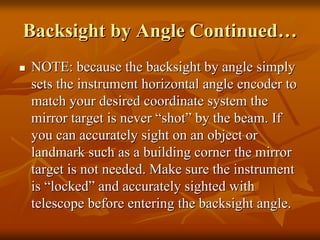
![BacksightBacksight by Angle continuedby Angle continued……
SelectSelect ““BacksightBacksight”” and thenand then
““AngleAngle”” from the menufrom the menu
Sight the landmark/target of knownSight the landmark/target of known
azimuth relative to instrument withazimuth relative to instrument with
telescopetelescope
SelectSelect ““AngleAngle”” from menu. Notefrom menu. Note
that the menu displays the zeniththat the menu displays the zenith
angle (ZA) and current horizontalangle (ZA) and current horizontal
angle (HAR) and is waiting for youangle (HAR) and is waiting for you
to enter the known angle withto enter the known angle with
[EDIT][EDIT]
Note: if you enter an azimuth angleNote: if you enter an azimuth angle
asas ““85.451485.4514”” this will be interpretedthis will be interpreted
as 85 degrees, 45 minutes, 14as 85 degrees, 45 minutes, 14
secondsseconds
IMPORTANT! You must selectIMPORTANT! You must select
[OK] to accept the angle.[OK] to accept the angle. Never useNever use
<Esc> to leave this screen!<Esc> to leave this screen!](https://image.slidesharecdn.com/totalstationsetupandoperation-150317145143-conversion-gate01/85/Sokkia-Total-station-setup-and-operation-23-320.jpg)
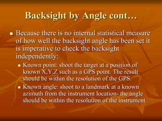
![BacksightBacksight by Coordinateby Coordinate
Use this method when you have 2Use this method when you have 2
known survey points with theknown survey points with the
instrument established on one and theinstrument established on one and the
mirror target on the other survey pointmirror target on the other survey point
From theFrom the ““MEASMEAS”” menu selectmenu select
[COORD] and then[COORD] and then ““StnStn..
OrientationOrientation””. Set the instrument. Set the instrument
coordinates withcoordinates with ““StnStn. Coordinate. Coordinate””
and then select [OK] and return toand then select [OK] and return to
““BacksightBacksight””
SelectSelect ““CoordCoord”” and then enter theand then enter the
backsightbacksight target coordinates (NBS,target coordinates (NBS,
EBS, ZBS) and select [OK]EBS, ZBS) and select [OK]
Sight in the target and inspect theSight in the target and inspect the
““AzmthAzmth”” (it should be reasonable for(it should be reasonable for
your coordinate system).your coordinate system).
Select [YES] to calibrate. If you donSelect [YES] to calibrate. If you don’’tt
select [YES] the coordinate system isselect [YES] the coordinate system is
still randomstill random](https://image.slidesharecdn.com/totalstationsetupandoperation-150317145143-conversion-gate01/85/Sokkia-Total-station-setup-and-operation-26-320.jpg)
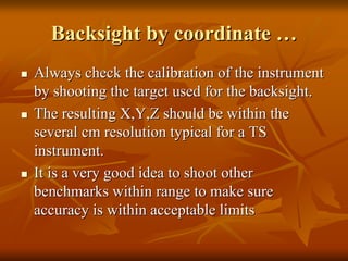
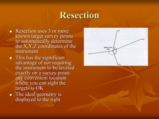
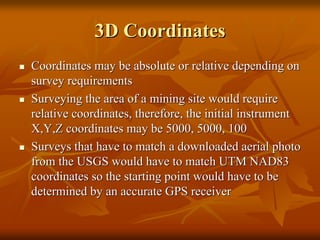
![Resection continuedResection continued……
Prior to resection enter survey markers as knownPrior to resection enter survey markers as known
points through thepoints through the ““MEMMEM”” menumenu
From theFrom the ““MEASMEAS”” menu selectmenu select ““[MENU][MENU]”” >>
[RESEC][RESEC]
The resection procedure requires that the knownThe resection procedure requires that the known
coordinates be defined first, and in the order thatcoordinates be defined first, and in the order that
they will be shotthey will be shot
In the top right screen the 1In the top right screen the 1stst
point has beenpoint has been
defined and the 2defined and the 2ndnd
point is being entered. Youpoint is being entered. You
can use [READ] to read in previously entered orcan use [READ] to read in previously entered or
measured pointsmeasured points
Press thePress the ““>>”” oror ““<<““ arrow to move to next orarrow to move to next or
previous pointprevious point
When all points are entered select [MEAS]When all points are entered select [MEAS]](https://image.slidesharecdn.com/totalstationsetupandoperation-150317145143-conversion-gate01/85/Sokkia-Total-station-setup-and-operation-29-320.jpg)
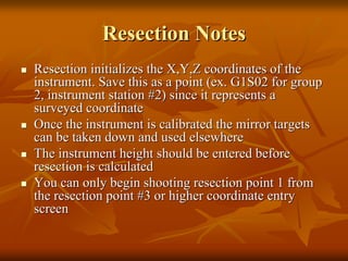
![Resection continuedResection continued……
The [MEAS] screen (right)The [MEAS] screen (right)
displays the point being shotdisplays the point being shot –– inin
this example the 1this example the 1stst
pointpoint
Choose [DIST] if you areChoose [DIST] if you are
shooting to a mirror target,shooting to a mirror target,
[ANGLE] if not[ANGLE] if not
Select [YES] to acceptSelect [YES] to accept
measurement, [NO] to remeasurement, [NO] to re--shoot,shoot,
[EDIT] to change target height[EDIT] to change target height
The [CALC] option will beThe [CALC] option will be
displayed when the standarddisplayed when the standard
deviation of northing and eastingdeviation of northing and easting
can be displayedcan be displayed](https://image.slidesharecdn.com/totalstationsetupandoperation-150317145143-conversion-gate01/85/Sokkia-Total-station-setup-and-operation-30-320.jpg)
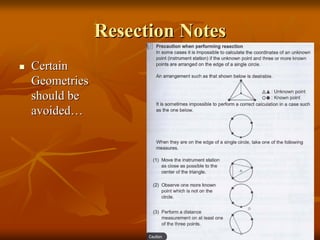
![Resection continuedResection continued……
Press [CALC] or [YES] on last point toPress [CALC] or [YES] on last point to
display the calculated instrumentdisplay the calculated instrument
coordinates and the standard deviation ofcoordinates and the standard deviation of
easting (easting (σσEE) and northing () and northing (σσN).N). PressPress
[OK] to finish Resection, and then[OK] to finish Resection, and then
[YES] to set the[YES] to set the backsightbacksight
azimuth to the 1azimuth to the 1stst shot pointshot point
Press [RESULT] to display the residuals ofPress [RESULT] to display the residuals of
each shot pointeach shot point-- large deviations identifylarge deviations identify
““badbad”” pointspoints
If there are no problems press {Esc} toIf there are no problems press {Esc} to
return to main resection screenreturn to main resection screen
The standard deviations are a measure ofThe standard deviations are a measure of
the accuracy. They should be in the range ofthe accuracy. They should be in the range of
several cmseveral cm’’s for most surveyss for most surveys](https://image.slidesharecdn.com/totalstationsetupandoperation-150317145143-conversion-gate01/85/Sokkia-Total-station-setup-and-operation-31-320.jpg)

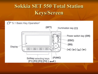
The document provides instructions for setting up and operating a Sokkia SET total station for surveying tasks. It describes how to level the instrument, perform calibration by backsight or resection, and take measurements such as distance and height. Key steps include leveling the instrument for accurate results, establishing orientation by shooting a known point or angle, and checking calibration by re-measuring control points. The document emphasizes proper setup, calibration checking, and understanding coordinate systems for accurate surveying work.