Downloaded 132 times

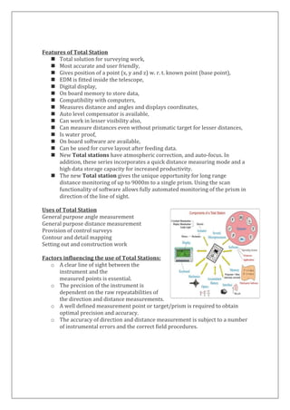
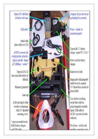
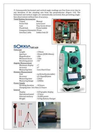
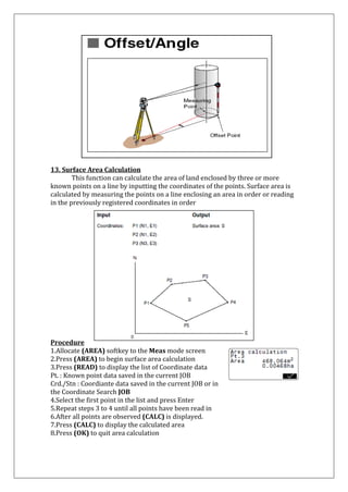
![Setting up the Instrument:
Centering:
1. Place the legs at equal intervals and the
head
is approximately level
2. Fix the tripod shoes in the ground
3. Place the instrument on the tripod stand
4. Supporting the instrument with one hand,
tighten the centering screw on the bottom
of the unit
5. Looking through the optical plummet eye
piece
focus on the Surveying point
Levelling:
1. Adjust the foot screws to center the surveying
point in the optical plummet reticule
2. Center the bubble in the circular level by
shortening or by lengthening the tripod leg
3. Turn the leveling screws until the bubble is
centered in the center circle
4. Loosen the horizontal clamp to turn the upper part of the
instrument until the plate level is parallel to a line between
leveling foot screws A & B
5. Center the air bubble using leveling foot screws A & B
simultaneously
6. Turn the upper part of the instrument through 900
7. The plate level is now perpendicular to the foot screws A & B
8. Center the air bubble using leveling foot screw C
Levelling the Screen:
1. Press [ON] to power on
2. Press [TILT] in the second page of Meas
mode to display the circular level on the screen
3. Center the bubble in the circular level
4. Set the tilt angle to 00 using foot screws A & B
for the X direction and leveling screw C for Y direction
Focusing and Target Sighting
1. Look through the telescope eyepiece at a
bright background
2. Turn the eyepiece clockwise, anticlockwise little by
little until just before the reticle image becomes
focused
3. Loosen the vertical and horizontal clamps, then use
the peep sight to bring the target in to the field of
view.
Tight both clamps
4. Turn the telescope focusing ring to focus on the target
5. Turn the vertical and horizontal and vertical fine motion screws
to align the target with the reticle
6. Readjust the focus with the focusing ring until there is no
parallax between the target image and the reticle](https://image.slidesharecdn.com/totalstation-2013-141104111332-conversion-gate01/85/Total-station-15-320.jpg)
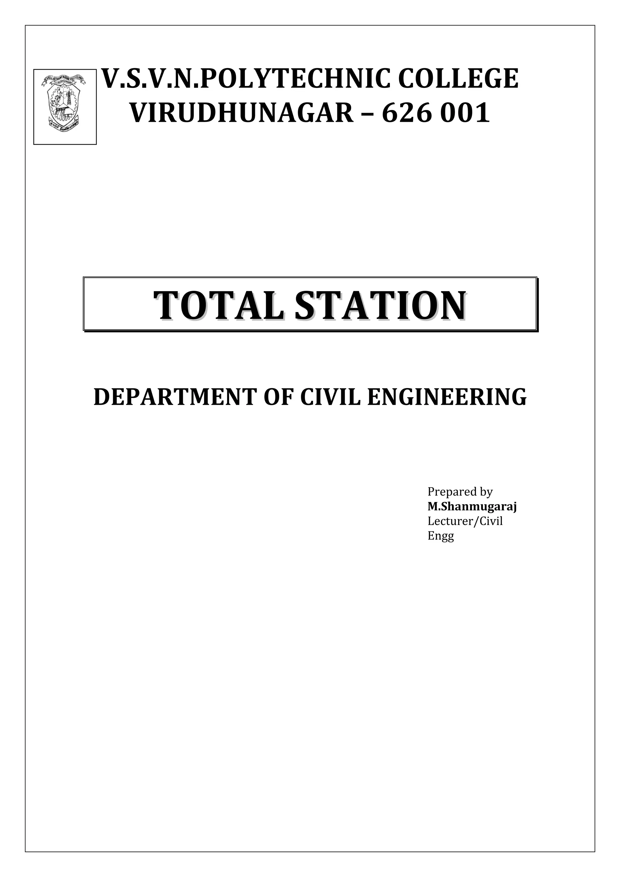
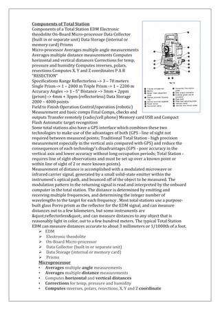
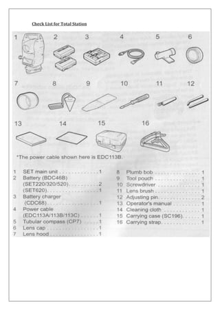
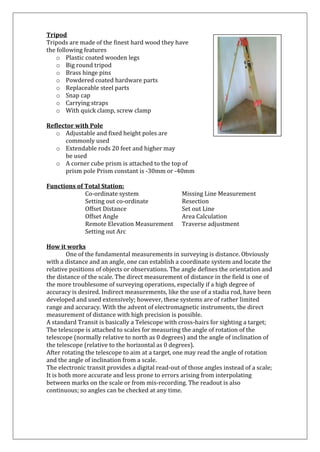
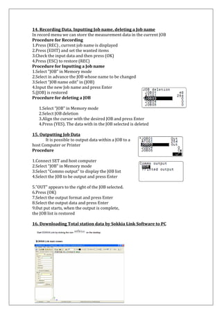
![7. Resection Measurement:
Resection is used to determine the coordinates of an instrument station by performing multiple measurements of points whose values are known. Registered coordinate data can be recalled and set as known point data.
7.1 Coordinate Resection Measurement
N, E, Z of an instrument is determined by this measurement
Procedure
1. Press [RESEC] to begin resection measurement
2. Select “NEZ” and press [EDIT] to input the known point
3. Set the coordinates for the first point known point
4. Press {>>} to move to the second point
5. When all required known points have been set press [MEAS]
(Registered coordinates can be used by pressing [READ])
6. Sight the first known point and press [DIST] to begin measurement
7. Press [YES] to use the measurement results of the first known point
8. Repeat procedures 6 to 7 in the same way from the second point
9. When the minimum quantity of observation data required for the calculation is present, [CALC] is displayed
10. Press [CALC] or [YES] to start calculations automatically
11. Press [RESULT] to check the result
12. If there are no problems with the result, press {ESC} got to 17
13. If there are problems press [BAD]. “*” is displayed on the left of the point. Repeat for all results that include problems
14. Press [RE CALC] to perform calculation again
15. If there are no problems with the result go to 17
16. If problems with the result occur again, perform from the step 6
17. Press [OK] to finish the resection measurement.
18. The instrument station coordinate is set
19. Press [YES] when you want to set the azimuth angle of the first known point as the back sight point](https://image.slidesharecdn.com/totalstation-2013-141104111332-conversion-gate01/85/Total-station-25-320.jpg)
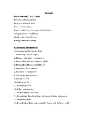
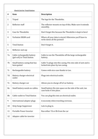
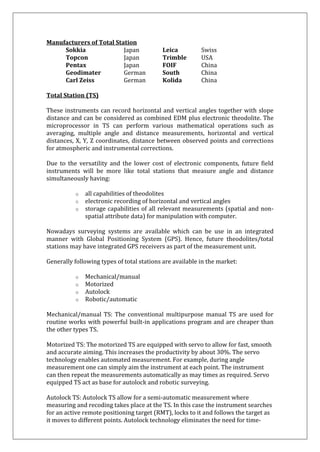
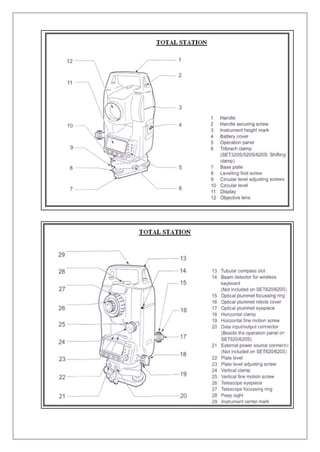
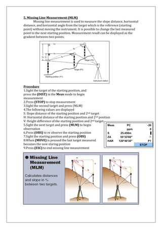
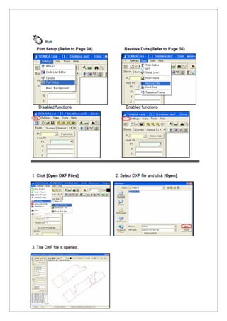
![8. Setting – Out Measurement Setting out measurement is used to set out the required point The horizontal angle difference and distance difference are calculated and displayed using the following formulae. Horizontal angle difference dHA = Horizontal angle of setting–out data–measured horizontal angle Distance difference Sdist : S-O S = measured slope distance–slope distance of setting–out data Hdist : S-O H = measured horizontal distance-horizontal distance of S-O data Vdist : S-O V = measured height difference-height difference of S-O data
Setting out data can be input various modes: slope distance, horizontal distance, height difference, coordinates and REM measurement
In slope distance, horizontal distance, height distance, and coordinate mode, registered coordinates can be recalled and used as setting-out coordinates
In slope distance, horizontal distance and height difference, S/H/V distances are calculated from the read in setting-out coordinate, instrument station data, instrument height, and target height
8.1 Distance Setting – out Measurement The point to be found based on the horizontal angle from the reference direction and the distance from the instrument station
Procedure
1. Press [S-O]
2. Enter the instrument station data.
3. (Refer 6. Coordinate data)
4. Set the azimuth angle of the backsight point
5. Select “S-O data”
6. Press [▲S-O] to select distance input mode
7. Each time [▲S-O] is pressed: S-O S (Slope distance), S-O H (horizontal distance), S-O V
(Height difference), S-O Coord (Coordinates), S-O Ht. (REM measurement).
8. When [READ] is pressed, registered coord. can be recalled and used
9. Press [EDIT] and set the following items
(i) Sdist/Hdist/Vdist:distance from the](https://image.slidesharecdn.com/totalstation-2013-141104111332-conversion-gate01/85/Total-station-26-320.jpg)
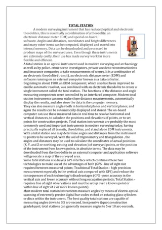
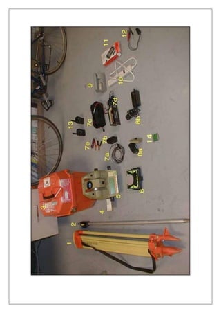
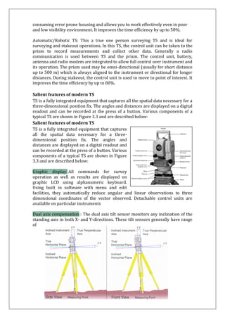
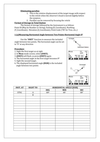
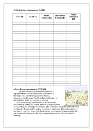
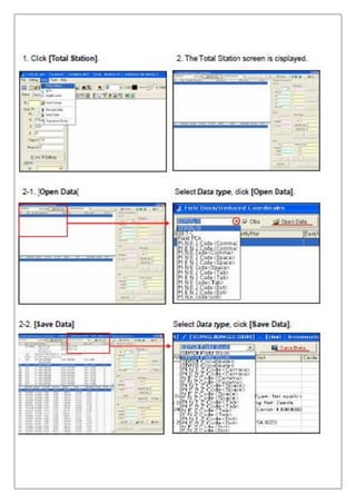
![instrument station to the position to be set out
(ii) H ang: included angle between the direction of the reference and the point to be set out
10. Pressing [COORD] in the second page allows you
to enter the coordinates of the point to be set out
11. Press [OK] to set the input values
12. Rotate the top of the instrument until “dHA” is 00
13. Place the target on the sight line
14. Press [OBS] to start distance measurement
15. The target and the distance of the point to
be set out is displayed (S-O H)
16. Move the prism forward and backward until setting-out distance is 0m.
17. If [S-O H] is “+”, move the prism toward yourself, if it is “-“ move the prism away from yourself
18. Press {ESC} to return to <S-O>
← : Move the prism to left →: Move the prism to right ↓ : Move the prism forward ↓: Move the prism away 8.2 Coordinates Setting-out Measurement
After setting the coordinates for the point to be set out, the SET calculates the setting out horizontal angle and horizontal distance. By selecting the horizontal angle and the horizontal distance setting out functions, the required coordinates location can be set out
Procedure
1. Press [S-O]
2. Enter the instrument station Data
3. Set the azimuth angle of the backsight point
4. Select “S-O data” and press [▲S-O] until <S-O Coord> displayed
5. Press [EDIT]. Enter the coordinates of the
setting out point
6. When [READ] is pressed, registered coordinates can be recalled and used as S-O coordinates
7. Press [OK] to set the setting out data
8. Rotate the top of the instrument until “dHA” is 00](https://image.slidesharecdn.com/totalstation-2013-141104111332-conversion-gate01/85/Total-station-27-320.jpg)
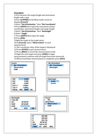
![9. Place the target on the sight line
10. Press [OBS] to begin coordinate setting out measurement
11. Move the prism forward and backward until the
setting out distance is 0m
12. If [S-O H] is “+”, move the prism toward yourself, if it is “-“ move the
prism away from yourself
13. By pressing [←,→], an arrow pointing to the left or right displays which direction the target should be moved
← : Move the prism to left
→: Move the prism to right ↓ : Move the prism forward ↑: Move the prism away
14. Press {ESC} to return to <S-O>
8.3 REM Setting-out Measurement
To find a point where a target cannot be directly installed, perform REM setting-out measurement
Procedure
1. Install a target directly below or directly above the point to be found, then use a measuring tape to measure
the target height (height from the surveying point to the target height)
2. Press [S-O] in the Meas mode screen to display <S-O>
3. Enter “S-O data” and press [▲S-O] until <S-O Ht.> is displayed
4. Press [EDIT]
5. After in putting the data, press [OK]
6. Press [REM] to begin REM setting-out measurement
7. Move the telescope to find out the point to be set out
▲
▲ : Move the telescope near the zenith ▼ ▼ : Move the telescope near the nadir
8. When the measurement is completed, press {ESC} to restore <S-O>.
9.Setting-Out Line Setting out line is used for setting out a required point at a designated distance from the baseline and for finding the distance from the baseline to a measured point.
9.1 Defining Baseline
To perform setting-out line measurement, first, define the baseline. The baseline can be defined by inputting the coordinates of the two points. The scale](https://image.slidesharecdn.com/totalstation-2013-141104111332-conversion-gate01/85/Total-station-28-320.jpg)
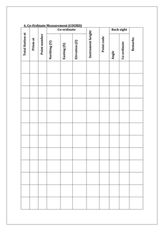
![factor value is the difference between the input coordinates and the observed coordinates. Scale (X,Y) = Hdist (horizontal distance calculated from the measured value)
Hdist (horizontal distance calculated from the input coordinates)
Procedure
1. Allocate the [S-O LINE] to the Meas mode screen
2. Press [S-O LINE] to display <Set-out line>
3. Enter the instrument station data
4. Select “Define baseline” in <Set-out line> and
press [EDIT]
5. When [READ] is pressed registered
coordinates can be recalled and used
6. Enter the first point data and press {↩}
7. Press {▶} to move to the second point
8. Press [EDIT] and enter the second point data
9. Press {FUNC}. [MEAS] is displayed
10. When not observing the first point and the
second point, go to step 16
11. Press [MEAS] to move observation of the first point
12. Sight the first point and press [OBS]
13. Press [YES] to use the measurements
results for the first point
14. Sight the second point and press [OBS]
15. Press [YES] to use the measurement results of the second point
16. Press [OK] to define the base line
17. <Set-out line> is displayed](https://image.slidesharecdn.com/totalstation-2013-141104111332-conversion-gate01/85/Total-station-29-320.jpg)
![9.2 Setting-out Line Point Setting-out line measurement can be used to find the required point ccordinate by inputting the length and offset based on the baseline. Before performing setting-out line point, the base line must be defined
Procedure
1. Select “Point” in <Set-out line>
2. Press [EDIT]
3. Length: Distance along the baseline from the first point to the position at which a line extending from the required point intersects the baseline at right angles (X direction)
4. Offset: Distance from the required point to the position at which a line extending from the required point intersects the base line at
right angles (Y direction).
5. Press [OK]. The coordinate value of the required
point is calculated and displayed
6. Press {ESC}
9.3 Setting–out Line Line Setting-out line line measurement tells how far horizontally yhe measured point is from the base line and how far vertically the measured point is from the connected line. The base line can be offset in a horizontal direction if necessary. Before performing setting-out line line, the base line must be defined](https://image.slidesharecdn.com/totalstation-2013-141104111332-conversion-gate01/85/Total-station-30-320.jpg)
![Procedure
1. Select “Line” in <Set-out line>
2. Press [EDIT] and enter the offset value
3. Offset : How much to move the base line
4. + ve value indicates right side
5. – ve value indicates left side
6. When not setting offset value, go to step 7
7. Sight the target and pres [OBS]
8. Press [YES] to use the measurement results
9. Displays the difference between the measured point and
the baseline
10. Offline : +ve indicates the point is on the right side
of the baseline and a negative value indicates it is on the left
11. “Cut” indicates that the point is below the baseline
12. “Fill” indicates that the point is above the baseline
13. Length : Distance along the baseline from the first
point to the measured point
14. Press [NO] to observe the target point again.
15. Sight the next target and press [OBS] to continue the measurement
10. Setting – Out Arc
This mode allows us to define an arc from various arc parameters, such as From Pt coordinates, and set out this arc as well as points (offsets) along it.
10.1 Defining an Arc An arc can be defined by entering arc parameters such as arc radius, angle, coordinates for the From point, Center point, To point etc.
Procedure
1. Press [MENU], select “Set-out arc”
2. Enter the instrument station data.
3. Select “Define arc” in <Set-out arc>
4. When [READ] is pressed, registered coordinates
can be recalled and used](https://image.slidesharecdn.com/totalstation-2013-141104111332-conversion-gate01/85/Total-station-31-320.jpg)
![5. Enter the arc From point data and press [OK]
6. Press {▶} / {◄} to select coordinates then press [OK]
7. To : Enter arc To point
8. To / Center : Enter arc To point and Center point
9. To / Intersect : Enter arc To point and Intersect point
10. Center : Enter arc Center point
11. Intersect : Enter arc Intersect point
12. Center / Intersect : Enter arc Center point and Intersect point
13. Enter the coordinates specified in step 6 then press {↩}
14. Enter other arc parameters
15. Direction (whether the arc turns right /
left from the From point)
16. Radius (radius of the arc)
17. Angle (Subtended angle)
18. Arc (distance along the arc)
19. Chord (straight line distance between the
From and To points)
20. Tan ln (tangent length)
21. Bk tan (back tangent length)
22. Enter curve parameters then press {↩}.
Other parameters will be calculated
23. Press [OK] on the screen of step 22 to
define the arc
24. <Set-out arc> is displayed
25. Move to setting-out arc measurement.](https://image.slidesharecdn.com/totalstation-2013-141104111332-conversion-gate01/85/Total-station-32-320.jpg)
![11. Point projection Point projection is used for projecting a point on to the baseline. The point to projection can be either measured or input. Displays the distances from the first point and point to point to the position at which a line extending from point to point intersects the baseline at right angles
11.1 Defining Baseline
1. Press [P-PROJ] to display <Point projection>
2. Enter the instrument station data then define baseline
3. Press [OK] to define the baseline. <Point projection>
is displayed. Move to point projection measurement
11.2 Point Projection
Before performing point projection, the baseline must be defined. Procedure
1. Define the baseline
2. Press [P-PROJ] to display <Point projection>
3. Press [EDIT], enter the point coordinate
4. Press [OBS] to observe the point ot project
5. When recording the data as a known point,
press {FUINC}, and then press [REC]
6. Press [OK]. The following items are calculated and
displayed
7. Length : Distance along the baseline from the first
point to the projected point (X direction)
8. Offset : Distance from point to project to the position at which a line extending from point of project intersects the base line at right angles
9. d.Elev : Elevation between the baseline and the projection point
10. Press [XYZ] to switch the screen display to distance values
11. Press [REC]: records the coordinate value as a known point data
12. Press [▲S-O] to move to setting-out measurement
of the projected point
13. Press {ESC}. Continue the measurement](https://image.slidesharecdn.com/totalstation-2013-141104111332-conversion-gate01/85/Total-station-33-320.jpg)
![12.Offset Measurement
Offset measurements are performed in order to find a point where a target cannot be installed directly or to find the distance and angle to a point which cannot be sighted
It is possible to find the distance and angle to a point you wish to measure (target point) by installing the target at a location (offset point) a little distance from the surveying point to the offset point The target point can not be found in the three ways explained below
12.1 Single–distance Offset Measurement
Finding it by entering the horizontal distance from the target point to the offset point.
Procedure
1. Set the offset point to close to the target point and measure the distance between them, then set up a prism on the offset point
2. Sight the offset point and press [DIST]
3. The measurement results are
displayed. Press [STOP]
4. Press [OFFSET]
5. Enter the instrument station data
6. Select “Offset/Dist” and press [EDIT]](https://image.slidesharecdn.com/totalstation-2013-141104111332-conversion-gate01/85/Total-station-34-320.jpg)
![7. Input the following items
a. Horizontal distance from the target point to the offset point
b. Direction of the offset point
←: On the left of the target point
→: On the right of the target point
↓: Closer than the target point ↑: Beyond the target point
8. Press [OK] to calculate and display distance and angle of target point
9. Press [YES] to return to <Offset>
12.2 Angle Offset Measurement Sighting the direction of the target point to find it from the included angle. Install offset points for the target point on the right and left sides of and as close as possible to the target point and measure the distance to the offset points and the horizontal angle of the target point.
Procedure
1. Set the offset points close to the target point, then use the offset points as
the target
2. Sight the offset point and press [DIST]
3. The measurement results are displayed. Press [STOP]
4. Press [OFFSET]
5. Enter the instrument station data
6. Select “Offset/Angle” in <Offset>
7. Accurately sight the direction of the target point and press [OK]
8. After finishing measurement press [YES] to return to <Offset>](https://image.slidesharecdn.com/totalstation-2013-141104111332-conversion-gate01/85/Total-station-35-320.jpg)

The document provides an in-depth overview of total stations, which are advanced surveying instruments combining electronic theodolites and electronic distance meters. It covers their definition, features, components, setup procedures, and various measurement techniques, highlighting their versatility in fields such as construction, archaeology, and law enforcement. The document also details the advantages of total stations over traditional surveying methods, emphasizing their accuracy and efficiency in data collection and mapping.