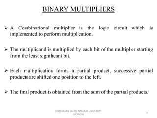
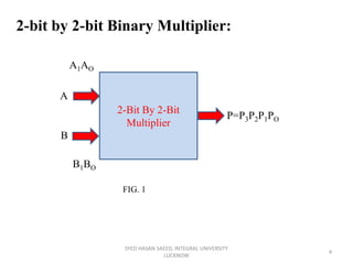
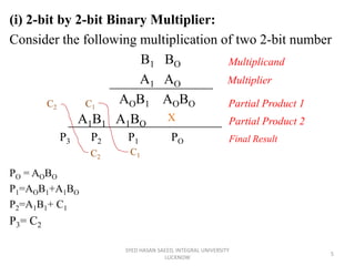
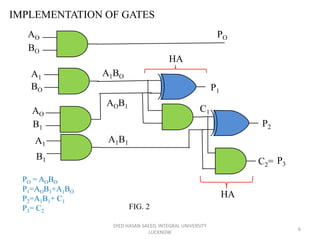
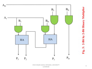
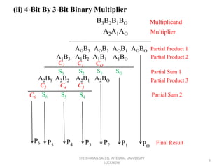
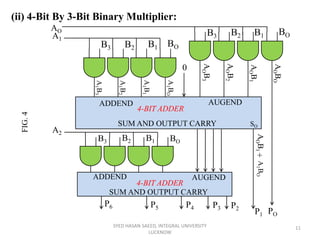
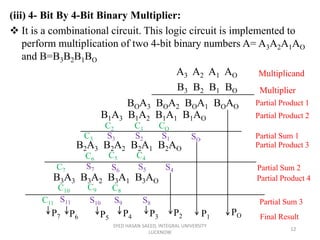
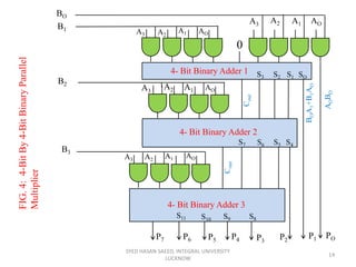
3. BINARY MULTIPLIERS
A Combinational multiplier is the logic circuit which is
implemented to perform multiplication.
The multiplicand is multiplied by each bit of the multiplier starting
from the least significant bit.
Each multiplication forms a partial product, successive partial
products are shifted one position to the left.
The final product is obtained from the sum of the partial products.
SYED HASAN SAEED, INTEGRAL UNIVERSITY
LUCKNOW
3
4. SYED HASAN SAEED, INTEGRAL UNIVERSITY
LUCKNOW
4
2-bit by 2-bit Binary Multiplier:
2-Bit By 2-Bit
Multiplier
A
B
A1AO
B1BO
P=P3P2P1PO
FIG. 1
5. (i) 2-bit by 2-bit Binary Multiplier:
Consider the following multiplication of two 2-bit number
B1 BO
A1 AO Multiplier
AOB1 AOBO
A1B1 A1BO
P3 P2 P1 PO
PO = AOBO
P1=AOB1+A1BO
P2=A1B1+ C1
P3= C2
SYED HASAN SAEED, INTEGRAL UNIVERSITY
LUCKNOW
5
Multiplicand
Partial Product 1
Partial Product 2
C1
C1
C2
C2
X
Final Result
6. IMPLEMENTATION OF GATES
SYED HASAN SAEED, INTEGRAL UNIVERSITY
LUCKNOW
6
AO
BO
PO
BO
A1
AO
B1
A1
B1
P1
P2
P3C2=
C1
A1BO
AOB1
A1B1
HA
HA
PO = AOBO
P1=AOB1+A1BO
P2=A1B1+ C1
P3= C2
FIG. 2
7. Multiplicand Bits are B1 and BO, Multiplier bits are A1 and AO and
the products is P3P2P1PO.
First partial product is formed by multiplying BO by AO and B1 by
AO
Multiplication of AO and BO produces 1, if both bits are 1;
otherwise it produces 0. This indicates an AND operation.
Therefore partial product can be implemented with AND gates.
The second partial product can be obtained by multiplying BO by A1
and B1 by A1 and shifted one position to the left.
The two partial product are added with two half adder circuits.
Usually there are more bits in the partial products and it is
necessary to use full adder to produce the sum of partial products.
2-bit by 2-bit Binary Multiplier shown in fig.3
SYED HASAN SAEED, INTEGRAL UNIVERSITY
LUCKNOW
7
8. SYED HASAN SAEED, INTEGRAL UNIVERSITY
LUCKNOW
8
HA HA
BOB1
BOB1
AO
A1
Fig.3:2-Bitby2-BitBinaryMultiplier
POP1P2P3
9. B3B2B1BO
A2A1AO
SYED HASAN SAEED, INTEGRAL UNIVERSITY
LUCKNOW
9
AOB3 AOB2 AOB1 AOBO
A1B3 A1B2 A1B1 A1BO
(ii) 4-Bit By 3-Bit Binary Multiplier
COC1C2
SOS1S2S3
A2B3 A2B2 A2B1 A2BO
C3C4C5
S4S5S6C6
PO
P1P2P3P4P5
P6
Multiplicand
Multiplier
Partial Product 1
Partial Product 2
Partial Sum 1
Partial Product 3
Partial Sum 2
Final Result
10. • The partial product terms are produced via bit by bit multiplication.
This is equivalent to ANDing of two bits.
• Finally the partial product terms in each column are added together
to get final product terms.
• No. of AND gates= m * n, where m= multiplier bits and
n= multiplicand bits.
• (m-1)n-bit adders required to produce a product of m+n bits.
• For 4-bit by 3-bit multiplier, the no. of AND gates=3*4=12
• Two 4-bit adders are required to produce product of seven bits.
• Fig. 2 shows the 4-bit by 3-bit multiplier.
SYED HASAN SAEED, INTEGRAL UNIVERSITY
LUCKNOW
10
11. (ii) 4-Bit By 3-Bit Binary Multiplier:
SYED HASAN SAEED, INTEGRAL UNIVERSITY
LUCKNOW
11
B2 B1 BOB3
BOB1B2B3
ADDEND AUGEND
SUM AND OUTPUT CARRY
ADDEND AUGEND
SUM AND OUTPUT CARRY
4-BIT ADDER
4-BIT ADDER
AO
A1
A2
POP1
P2P3P4P5
P6
0
BOB1B2B3
AOBO
AOB1
AOB2
AOB3
A1BO
A1B1
A1B2
A1B3
AOB1
+
A1BO
SO
FIG.4
12. (iii) 4- Bit By 4-Bit Binary Multiplier:
It is a combinational circuit. This logic circuit is implemented to
perform multiplication of two 4-bit binary numbers A= A3A2A1AO
and B=B3B2B1BO
A3 A2 A1 AO
B3 B2 B1 BO
SYED HASAN SAEED, INTEGRAL UNIVERSITY
LUCKNOW
12
BOA3 BOA2 BOA1 BOAO
B1A3 B1A2 B1A1 B1AO
B2A3 B2A2 B2A1 B2AO
B3A3 B3A2 B3A1 B3AO
COC1C2
SOS1S2S3C3
C4C5C6
S4S5S6
S7C7
C8C9C10
S8S9S10S11C11
POP1P2P3P4P5P6P7
Multiplicand
Multiplier
Partial Product 1
Partial Product 2
Partial Product 3
Partial Sum 1
Partial Product 4
Partial Sum 2
Partial Sum 3
Final Result
13. In this process the first partial product is obtained by multiplying BO
with A3A2A1AO , the second partial product is formed by
multiplying B1 with A3A2A1AO , likewise for III and IV partial
products.
These partial products can be implemented with AND gates (as
shown in fig.)
These partial product are then added by using 4 bit parallel adder.
The three most significant bits of first partial product with carry
(considered as zero) are added with second partial term in first full
adder.
Then the result is added to the next partial product with carry out
and it goes on till the final partial product, finally it produces 8 bit
sum which indicates the multiplication of two binary numbers.
SYED HASAN SAEED, INTEGRAL UNIVERSITY
LUCKNOW
13
14. SYED HASAN SAEED, INTEGRAL UNIVERSITY
LUCKNOW
14
A1 AOA2A3
A3 A2
A1 AO
A3
A2 A1 AO
A3
AOA1A2
BO
B1
B3
B2
POP1P6
AOBO
BOA1+B1AO
P3P5 P2P7 P4
4- Bit Binary Adder 1
4- Bit Binary Adder 2
4- Bit Binary Adder 3
SOS1S2S3
Cout
S4S5S6S7
Cout
S8S9S10
S11
FIG.4:4-BitBy4-BitBinaryParallel
Multiplier
0
15. References:
• Digital Design, Pearson, 4th Edition.
• Digital Circuit and Design, S. Salivahanan and S. Arivazhagan,
Oxford University Press, 5th Edition.
• Digital Systems Principles & Applications, Ronald J. Tocci,
Prentice-Hall of India Pvt. Ltd. , 6th Edition.
SYED HASAN SAEED, INTEGRAL UNIVERSITY
LUCKNOW
15