Error Reduction of Modified Booth Multipliers in Mac Unit

Abstract: The fixed-width multiplier is well attractive to many multimedia and digital signal processing systems. It proposes a reduction of truncation error from 16-bit to 8-bit MSB bits (Truncated output) using simple error reduction circuit. The Fixed width modified booth multiplier is used to minimize the partial product matrix of Booth multiplication. Multiplication is binary mathematical operation scaling one number by another. Lead the design of high accuracy, low power and area in MAC unit and compare with the Wallace tree multiplier. The system will be designed using VHDL coding (Very High speed Integrated Circuit Hardware Descriptive Language). Index Terms: Multiplier and Accumulator, Most significant bits, Modified booth multiplier, error reduction circuit, fixed width multiplier

Recommended
Recommended
More Related Content
Viewers also liked
Viewers also liked (20)
Similar to Error Reduction of Modified Booth Multipliers in Mac Unit
Similar to Error Reduction of Modified Booth Multipliers in Mac Unit (20)
More from IOSR Journals
Recently uploaded
Recently uploaded (20)
Error Reduction of Modified Booth Multipliers in Mac Unit
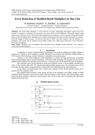
- 1. IOSR Journal of Electronics and Communication Engineering (IOSR-JECE) e-ISSN: 2278-2834,p- ISSN: 2278-8735. Volume 7, Issue 6 (Sep. - Oct. 2013), PP 20-26 www.iosrjournals.org www.iosrjournals.org 20 | Page Error Reduction of Modified Booth Multipliers in Mac Unit K.Santhana Lakshmi1 , G. Brindha2 , A.Andamuthu3 Assistant Professor1 , Assistant Professor2 , Assistant Professor3 Department of Electronics and Communication Engineering, Muthayammal Engineering College. Abstract: The fixed-width multiplier is well attractive to many multimedia and digital signal processing systems. It proposes a reduction of truncation error from 16-bit to 8-bit MSB bits (Truncated output) using simple error reduction circuit. The Fixed width modified booth multiplier is used to minimize the partial product matrix of Booth multiplication. Multiplication is binary mathematical operation scaling one number by another. Lead the design of high accuracy, low power and area in MAC unit and compare with the Wallace tree multiplier. The system will be designed using VHDL coding (Very High speed Integrated Circuit Hardware Descriptive Language). Index Terms: Multiplier and Accumulator, Most significant bits, Modified booth multiplier, error reduction circuit, fixed width multiplier. I. Introdution A multiplier is a factor of proportionality that measures how much an endogenous variable changes in response to a change in some exogenous variable. Multipliers are the basic and important building blocks of VLSI systems. The technology considers the power consumption, area and accuracy. Accuracy is one of the backbones of the multipliers. To achieve the high performance of modified booth encoding which reduces the partial products. N*N fixed width multipliers that generate only the N most significant bits (MSB) and to maintain a fixed word size. Truncation error will be high in this type of multiplier. This truncation error can be reduced by using error reduction circuit; it can be added estimated carry value of the reversed adder cells. For reducing the partial product output means, the truncation error will be occurring. The final output of partial product is used in MAC unit, DSP applications, and multimedia. To get better error performance with a simple error reduction circuit, Booth encoded outputs are to generate the error reduction value. By modified booth encoding, which groups the bits of the multiplier into triplets. Output of MBE (Modified Booth Encoder) is given to the input of Partial Product. Used to reduce the partial product steps, using truncation method to reduce the partial product from 16 bit to 8bit, that is truncating the LSB (Least Significant Bits) bits only. II. Modified Booth Encoder Fig.1. Circuit diagram of modified booth encoder Conditions: 000 All Zero‟s 001 Input Value (+M) 010 Input Value (+M)
- 2. Error Reduction Of Modified Booth Multipliers In Mac Unit www.iosrjournals.org 21 | Page 011 Shift + Input Value (+2M) 100 Two‟s Complement + shift (-2M) 101 Two‟s Complement + Input (-M) 110 Two‟s Complement + Input (-M) 111 All Zero‟s The above diagram has Y inputs and produces the output as Onei, Twoi, Zeroi, and Cori. Using 8*8 means take only the output as 8 (Instead of 16) that are called fixed width. The output of modified booth encoder is given to the input of partial product. 101 and 110, the output becomes two‟s complement and input value. In partial product the output comes only the One‟s complement, need two‟s complement means adding carry value1,get two‟s complement output. Table1: Modified Booth Encoder A. Function of Modified Booth Multiplier An example of Modified Booth Multiplier is in below: X 1 1 0 1 0 0 1 0 (Multiplicand) Y 1 1 0 1 0 0 1 1 (Multiplier) Take Y, i=3 i=1 Y 1 1 0 1 0 0 1 1 0 i=2 i=0 Condition: i= 0 to 3; j = 0 to 7; For i=0 1 1 0 Y2(0)+1=1 Neg(0)=1 Y2(0) =1 ; Y2(0)-1=0 One(0)=1 Y2(0) =1 ; Y2(0)+1=1 Two(0)=0 Y2(0)+1= 1 ; Y2(0)-1=0 Zero(0)=0 Y2(0)-1= 0 ; Y2(0)=1 ; Y2(0)+1=1 Cor(0)=1 For i=1 0 0 1 Y2(1)+1=1 Neg(1)=0 Y2(1) =1 ; Y2(1)-1=0 One(1)=1 Y2(1) =1 ; Y2(1)+1=1 Two(1)=0 Y2(1)+1= 1 ; Y2(1)-1=0 Zero(1)=0 Y2(1)-1= 0 ; Y2(1)=1 ; Y2(0)+1=1 Cor(1)=0 For i=2 0 1 0 Y2(2)+1=1 Neg(0)=0 Y2(2) =1 ; Y2(2)-1=0 One(2)=0 Y2(2) =1 ; Y2(2)+1=1 Two(2)=1 Y2(2)+1= 1 ; Y2(2)-1=0 Zero(2)=0 Y2(2)-1= 0 ; Y2(2)=1 ; Y2(2)+1=1 Cor(2)=0 For i=3 1 1 0 Y2(3)+1=1 Neg(0)=1 Y2(3) =1 ; Y2(3)-1=0 One(3)=1 Y2(3) =1 ; Y2(3)+1=1 Two(3)=0 Y2(3)+1= 1 ; Y2(3)-1=0 Zero(3)=0 Y2(3)-1= 0 ; Y2(3)=1 ; Y2(3)+1=1 Cor(3)=1 III. Partial Product The values of partial product bits are heavily dependent on the outputs of booth encoder. It explores the relation between the outputs of booth encoders and the carry value propagated from LPminor to LPmajor.
- 3. Error Reduction Of Modified Booth Multipliers In Mac Unit www.iosrjournals.org 22 | Page Yj Yj nYj 0 nYj-1 Twoi,Onei,Zeroi P Fig.2. Circuit diagram of Partial Product Multiplexer have Y inputs, P output, selection inputs (0 or 1) P will be equal to one of the inputs, depending upon the selection inputs. Minimum number of sign extension. The output is checked by using VHDL programming technique. A. Function of Partial product X 1 1 0 1 0 0 1 0 (Multiplicand) Y 1 1 0 1 0 0 1 1 (Multiplier) Take Y, i=3 i=1 Y 1 1 0 1 0 0 1 1 0 i=2 i=0 For i=0; j=0 to 7; PP0 0 0 1 0 1 1 0 1(1‟s Complement) For i=1; j=0 to 7; PP1 1 1 0 1 0 0 1 0 For i=2; j=0 to 7; PP2 1 1 0 1 0 0 1 0 For i=3; j=0 to 7; PP3 0 0 1 0 1 1 0 1(1‟s Complement) For i=0 0 0 1 0 1 1 0 1 (+) 1 0 0 1 0 1 1 1 0 (2‟s Complement) For i=3 0 0 1 0 1 1 0 1 (+) 1 0 0 1 0 1 1 1 0 (2‟s Complement) In the above calculation, only getting the ones complement output. 1 1 0 is the two‟s complement type, but the partial product output is ones complement, so need to add correction bit 1.Finally getting the twos complement output. B. Partial Product Outputs 15 14 13 12 11 10 9 8 7 6 5 4 3 2 1 0 PP0 1 0 0 0 0 1 0 1 1 0 1 PP1 1 0 1 1 0 1 0 0 1 0 1 PP2 1 0 1 1 0 1 0 0 1 0 cor PP3 1 1 0 0 1 0 1 1 0 1 1(Cor) LPminor 0 0 0 0 1 0 0 0 0 0 0 1 0 1 1 0 Fig.3. Calculation of Partial Product To truncate the LPminor parts ,adding carry value 1 or 0 in LP(Least Product)major parts ,if carry is 0 means the output of 1 0 0 (PP0 of 10,9,8th digit)is same or carry is 1 means ,the output of 1 0 0 becomes 1 0 1. In above figure, LSB (Lest Significant Bits) bits are split into LP(Lest Product) major and LP(Least Product) minor parts. LP minor star9ts from digit 0 to 6 and LP minor parts starts 7th digit only. From 8th to 15th bit is the MSB(Most Significant Bits) bits Adding carry value in below diagram, 15 14 13 12 11 10 9 8 7 6 5 4 3 2 1 0 PP0 1 0 0 0 0 1 0 1 1 0 1 PP1 1 0 1 1 0 1 0 0 1 0 1(cor) PP2 1 0 1 1 0 1 0 0 1 0 PP0 1 1 0 0 1 0 1 1 0 1 (Adding carry value) 0 1(Cor) LPminor
- 4. Error Reduction Of Modified Booth Multipliers In Mac Unit www.iosrjournals.org 23 | Page 1 1 1 1 1 0 1 1 1 MSB bits Fig.4. Adding Carry value in Partial Product In fig4, the output is same there is no error output so move to next example, to reducing the bits from 16 to 8.The example becomes, X=0 0 0 1 1 0 0 0 „0‟ (Multiplicand) Y=0 0 1 1 0 0 1 0 „0‟ (Multiplier) 1 0 0 i=0 0 0 1 i=1 1 1 0 i=2 0 0 1 i=3 The Output becomes, 1 0 0 = 1 1 0 0 1 1 1 1 0 0 1 = 0 0 0 1 1 0 0 0 1 1 0 = 1 1 1 0 0 1 1 1 0 0 1 = 1 1 0 0 1 1 1 1 1 0 0 becomes the two‟s complement output. There is no change in adding carry value in few types of partial product inputs. In above calculations have some changes in adding carry value of partial product that is trucation error wiil occur. To overcome the truncation, using simple error reduction circuit, truncation means eliminating the least significant bits. 15 14 13 12 11 10 9 8 7 6 5 4 3 2 1 0 PP0 1 0 0 0 0 1 0 1 1 0 1 PP1 1 0 1 1 0 1 0 0 1 0 1 PP2 1 0 1 1 0 1 0 0 1 0 cor PP3 1 1 0 0 1 0 1 1 0 1 1(Cor) 0 0 0 0 0 1 0 0 1 1 1 0 0 0 0 0 Fig.5. Example of Partial Product Adding carry value in below diagram is, 15 14 13 12 11 10 9 8 7 6 5 4 3 2 1 0 PP0 0 1 1 1 1 0 0 1 1 1 1 PP1 1 1 0 0 0 1 1 0 0 0 1 PP2 1 0 1 1 1 0 0 1 1 1 1 PP0 1 1 0 0 0 1 1 0 0 0 (Adding Carry Value) 0 1(Cor) 0 0 0 0 0 0 1 1 (Error output) MSB bits Fig.6. Example of Adding carry Value C. Truncation Error Truncation is the term for limiting the number of digits, discarding the LSB bits. It occurs, when a number cannot be fully represented due to memory limitations. Truncating would yield the same result as rounding, but truncation does not round up or round down the digits; it merely cuts off at the specified digit. Multiplication is required in Digital signal processing. A substantial hardware savings is realized by summing only the n+k most significant columns of the matrix. This method of multiplication is called truncated multiplication. Truncated multiplication leads to two sources of error: reduction error and rounding error. Reduction error occurs because the n-k least significant columns of the multiplication matrix is not used to compute the product. Rounding error occurs because the product is rounded to n bits. IV. Summary And Results The output of modified booth encoder is given to the input of partial product for reducing the partial product steps and to produce the uniformity of the modified booth encoder. Using truncation method (Adding carry value), for reducing from 16 bit output to 8 bit output. In the future, I have to design an error reduction circuit and apply the MAC (Multiplier and Accumulator) unit and finally compare the Wallace tree Multiplier. A. Modified booth Encoder Output
- 5. Error Reduction Of Modified Booth Multipliers In Mac Unit www.iosrjournals.org 24 | Page The modified booth encoder has two inputs X and Y. Only take Y as input and the output becomes Negation,Zero,One,Correction,Two. By modified booth encoding, which groups the bits of the multiplier into triplets. The output of Modified booth encoder is given to the input of Partial Product. B. product, sum and carry of PP Output The inputs are X and Y .Take Y as an input, these inputs are splitting into PP0, PP1, PP2, PP3.Depending on the input value the output becomes changed. T he output has Sum, Carry and Product. C. Adding carry value Output The splitting of the (Partial Product) PP0, PP1, PP2, PP3 and adding this partial products using half adder, full adder. The reduction of 16 bit into 8 bit by using LSB bits and MSB bits .the LSB bits are split into LP major and LP minor parts. To eliminate the LP minor parts means some error occur in output ,so adding carry value 1 or 0 based on input values. Fig.7 Area for modified booth encoder
- 6. Error Reduction Of Modified Booth Multipliers In Mac Unit www.iosrjournals.org 25 | Page Fig.8 Power for modified booth encoder Fig.9 Area for Wallace tree multiplier Fig.10 Power for Wallace tree multiplier Table.1 Comparison of Wallace tree multiplier and Modified booth encoder with MAC unit Parameters Modified booth multiplier Wallace tree multiplier Power Consumption 43(mw) 55(mw) Gate Counts 1,138 1,211 Number of slices 79 out of 1,200 55 out of 1,200 Number of 4input LUT‟s 151 out of 2,400 98 out of 2,400 Number of bonded DOB‟s 25 out of 92 24 out of 92
- 7. Error Reduction Of Modified Booth Multipliers In Mac Unit www.iosrjournals.org 26 | Page References [1] Jiun-Pi Wang,Shiann-Rong Kuang ,Shish-Chiang Liang IEEE Trans on VLSI “High accuracy fixed width modified booth multipliers”,vol 19,No.1,PP.52-60,January 2011. [2] Kyung-Ju Cho, Kwang-Chul Lee, Jin-Gyun Chung, Member, IEEE, and Keshab K. Parhi, Fellow, IEEE, ” Design of Low-Error Fixed- Width Modified Booth Multiplier”, IEEE Transactions on Very Large scale Integration (VLSI) Systems, Vol. 12, No. 5,PP.522-531, May 2004. [3] Wen-Chang Yeh and Chein-Wei Jen, “High-Speed Booth Encoded Parallel Multiplier Design”, IEEE Transactions on Computers, Vol. 49, No. 7, PP.692-700, July 2000. [4] L. D. Van and C. C. Yang, “Generalized low-error area-efficient fixed width multiplier,” IEEE Trans. Circuits Syst. I, Reg. Papers, vol. 52, No.8, PP.1608–1619, August. 2005. [5] F.Elguibaly, “A fastparallel multiplier-accumulator using the modified Booth algorithm,” IEEE Trans. Circuits Syst. II, vol. 47, No. 9, PP.902-908, September 2000. [6] Oscal T.-C. Chen, Sandy Wang, and Yi-Wen Wu, ” Minimization of Switching Activities of Partial Products for Designing Low-Power Multipliers”, IEEE Transactions on very Large Scale Integration (VLSI) Systems, Vol. 11, No. 3,PP.418-432, June 2003. [7] C. N.Marimuthu, P. Thangaraj, “Low Power High Performance Multiplier”, ICGST-PDCS, Vol.2, No.3, PP.12-22, December 2008. [8] J. M. Jou, S. R. Kuang, and R. D. Chen, “Design of low-error fixed widthmultiplier for DSP applications,” IEEE Trans. Circuits Syst. I,Exp. Briefs, vol. 46, no. 6, PP. 836–842, June 1999