The document discusses Thevenin's theorem for DC networks. It states that any linear DC network containing voltage sources, current sources and resistances can be reduced to an equivalent circuit with one voltage source (Vth) in series with one resistance (Rth). Vth is defined as the open circuit voltage across the terminals and Rth is the equivalent resistance seen from the terminals. Independent sources are shortened or opened as needed. The procedure for obtaining the Thevenin equivalent involves removing the load resistance, calculating Vth and Rth, then reconnecting the load. An example circuit is worked through to illustrate the method.
THEVENIN’S THEOREM D.C.NETWORK
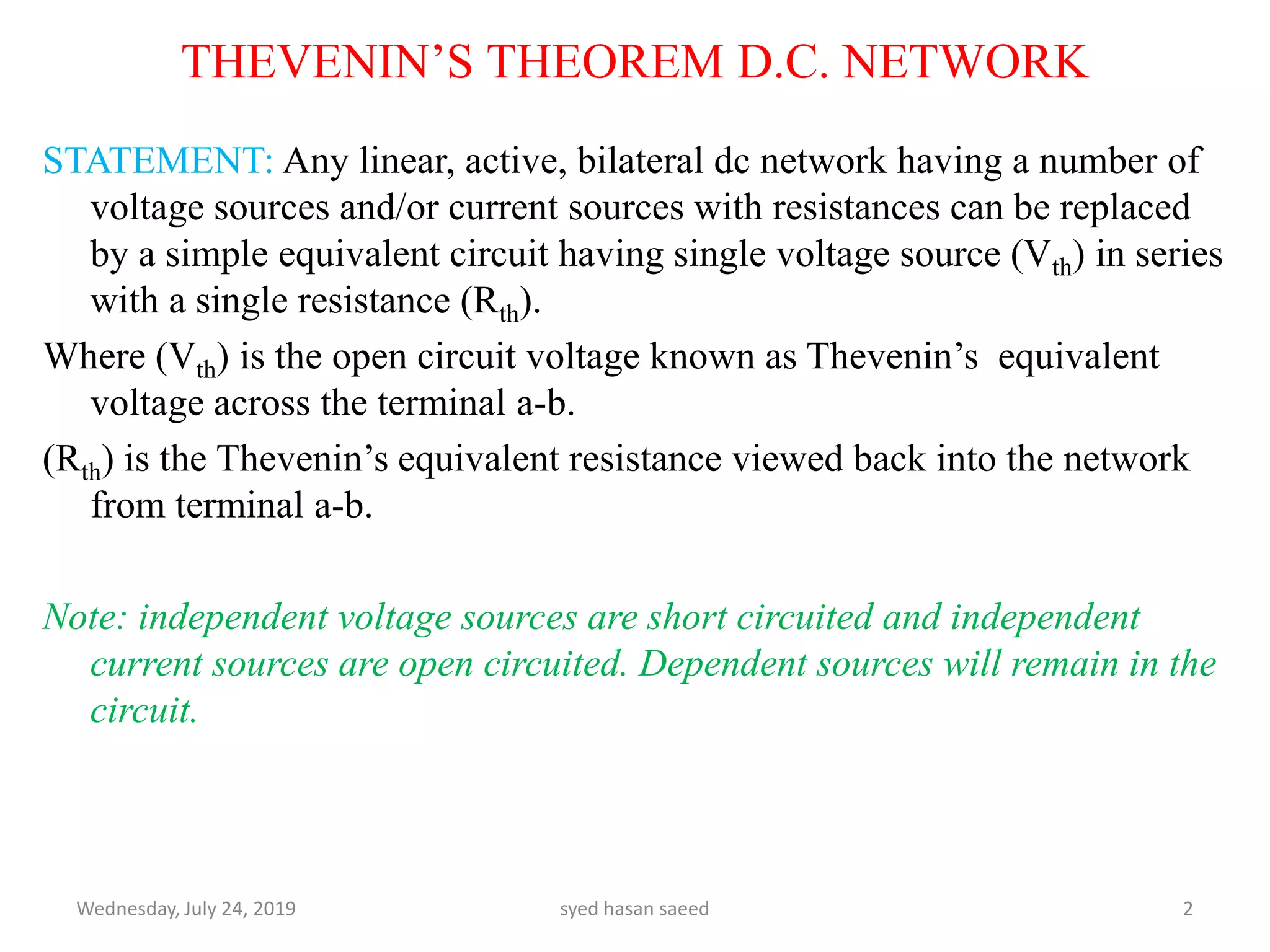
STATEMENT: Any linear, active, bilateral dc network having a number of
voltage sources and/or current sources with resistances can be replaced
by a simple equivalent circuit having single voltage source (Vth) in series
with a single resistance (Rth).
Where (Vth) is the open circuit voltage known as Thevenin’s equivalent
voltage across the terminal a-b.
(Rth) is the Thevenin’s equivalent resistance viewed back into the network
from terminal a-b.
Note: independent voltage sources are short circuited and independent
current sources are open circuited. Dependent sources will remain in the
circuit.
Wednesday, July 24, 2019 syed hasan saeed 2
3.
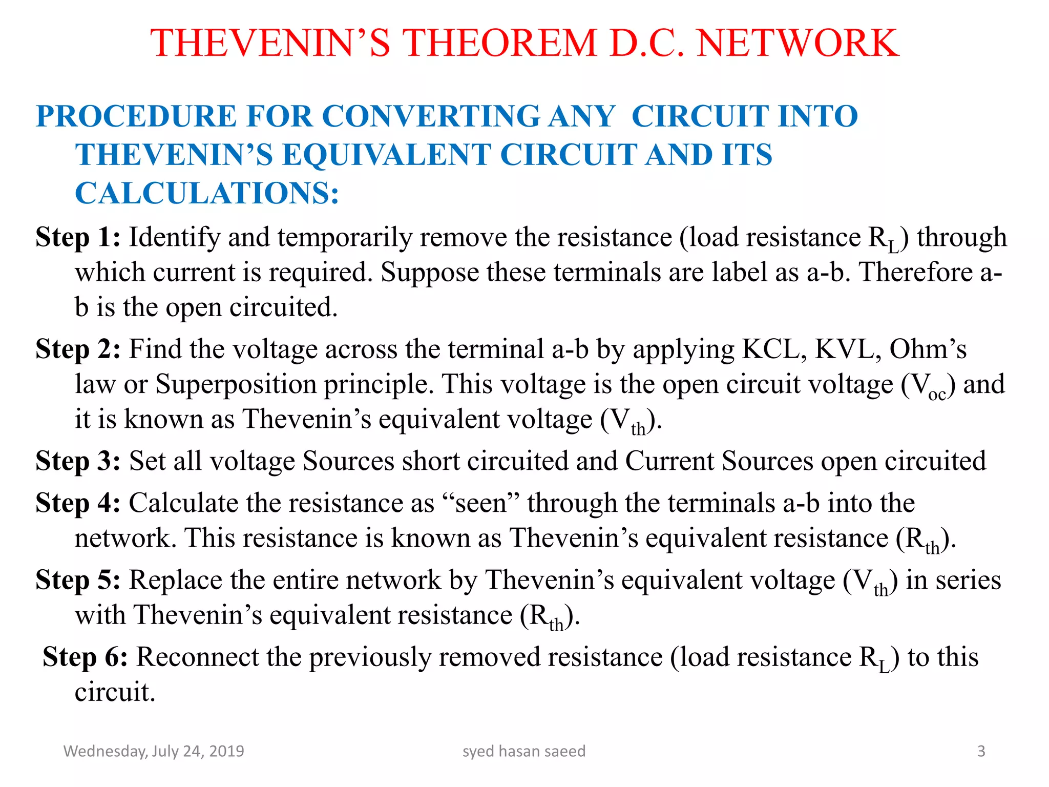
PROCEDURE FOR CONVERTINGANY CIRCUIT INTO
THEVENIN’S EQUIVALENT CIRCUIT AND ITS
CALCULATIONS:
Step 1: Identify and temporarily remove the resistance (load resistance RL) through
which current is required. Suppose these terminals are label as a-b. Therefore a-
b is the open circuited.
Step 2: Find the voltage across the terminal a-b by applying KCL, KVL, Ohm’s
law or Superposition principle. This voltage is the open circuit voltage (Voc) and
it is known as Thevenin’s equivalent voltage (Vth).
Step 3: Set all voltage Sources short circuited and Current Sources open circuited
Step 4: Calculate the resistance as “seen” through the terminals a-b into the
network. This resistance is known as Thevenin’s equivalent resistance (Rth).
Step 5: Replace the entire network by Thevenin’s equivalent voltage (Vth) in series
with Thevenin’s equivalent resistance (Rth).
Step 6: Reconnect the previously removed resistance (load resistance RL) to this
circuit.
Wednesday, July 24, 2019 syed hasan saeed 3
THEVENIN’S THEOREM D.C. NETWORK
4.
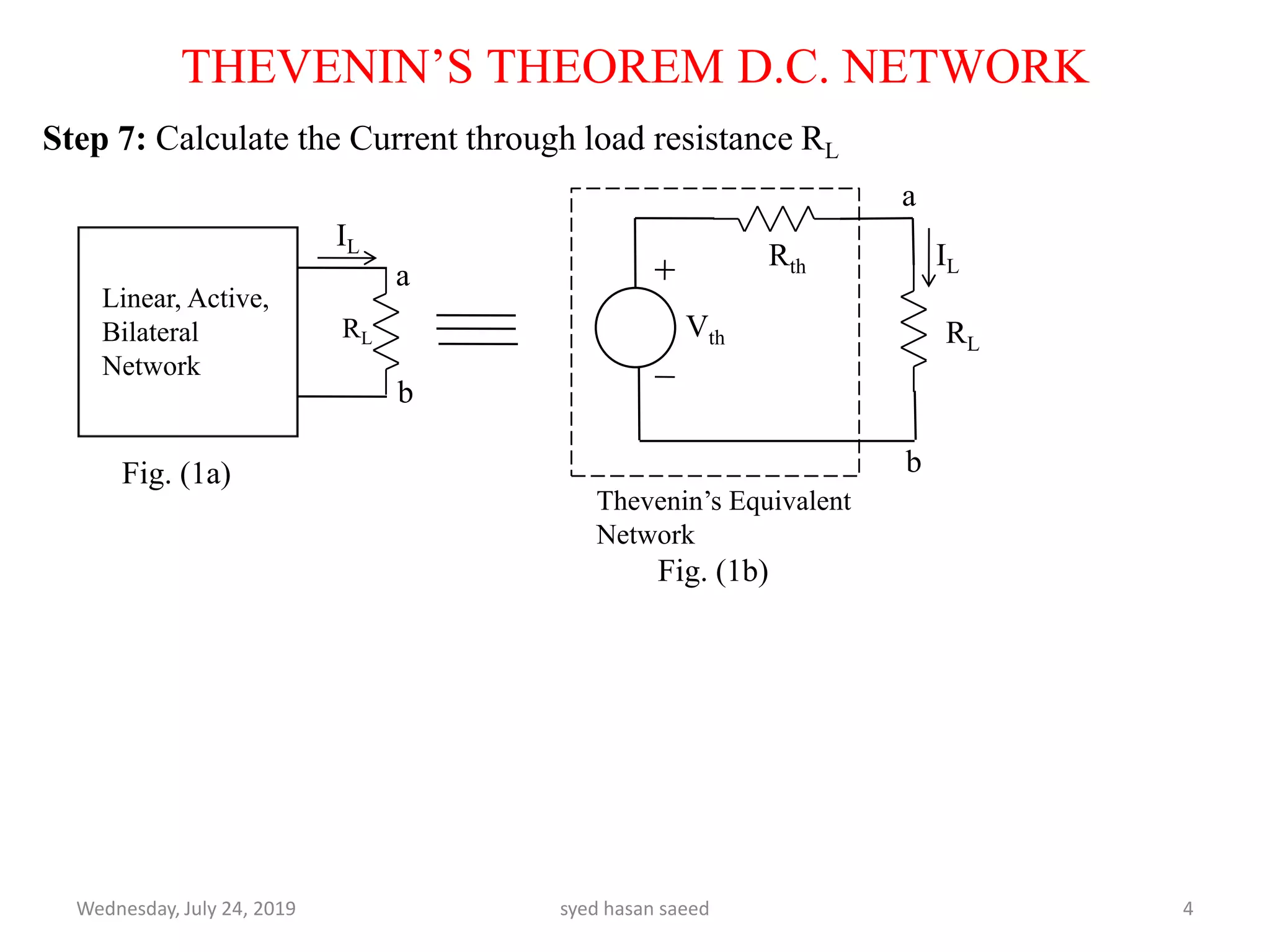
Step 7: Calculatethe Current through load resistance RL
Wednesday, July 24, 2019 syed hasan saeed 4
THEVENIN’S THEOREM D.C. NETWORK
Vth
Rth
RL
Linear, Active,
Bilateral
Network
RL
a
b
b
a
IL
IL
Thevenin’s Equivalent
Network
Fig. (1a)
Fig. (1b)
5.
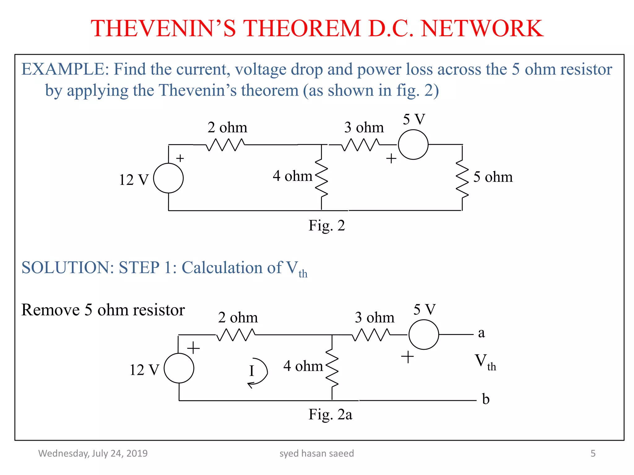
EXAMPLE: Find thecurrent, voltage drop and power loss across the 5 ohm resistor
by applying the Thevenin’s theorem (as shown in fig. 2)
SOLUTION: STEP 1: Calculation of Vth
Remove 5 ohm resistor
Vth
Wednesday, July 24, 2019 syed hasan saeed 5
THEVENIN’S THEOREM D.C. NETWORK
12 V
2 ohm 3 ohm
4 ohm 5 ohm
Fig. 2
5 V
12 V
2 ohm 3 ohm
4 ohm
5 V
a
b
I
Fig. 2a
6.
Apply KVL inLHS mesh:
12 - 2I - 4I = 0
I = 2A
Apply KVL in RHS mesh :
- Vth + 4I -3I -5 = 0
Put I = 2A
Vth = -3V
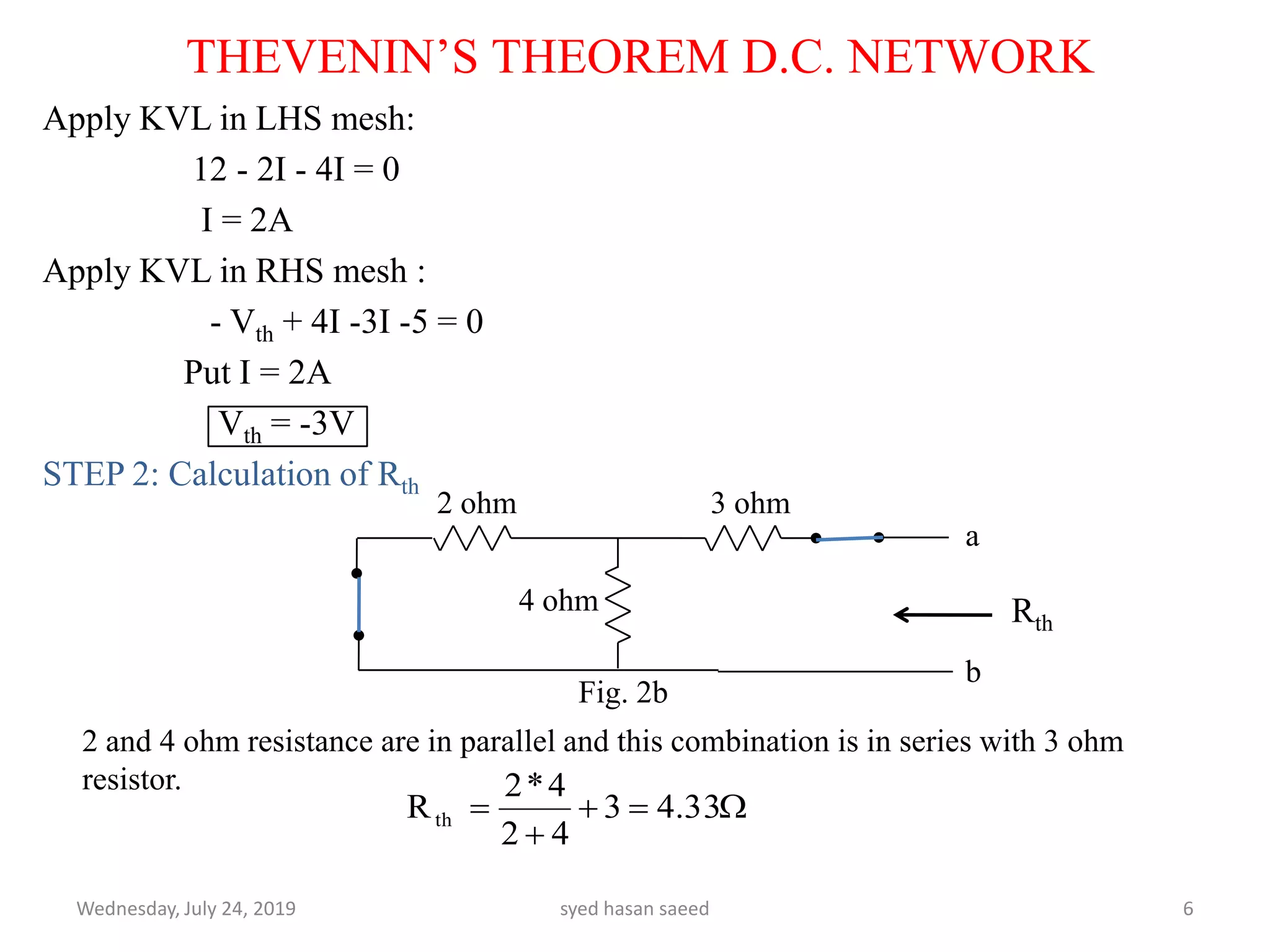
STEP 2: Calculation of Rth
Wednesday, July 24, 2019 syed hasan saeed 6
THEVENIN’S THEOREM D.C. NETWORK
2 ohm 3 ohm
4 ohm Rth
a
b
2 and 4 ohm resistance are in parallel and this combination is in series with 3 ohm
resistor.
33.43
42
4*2
Rth
Fig. 2b
7.
THEVENIN’S THEOREM D.C.NETWORK
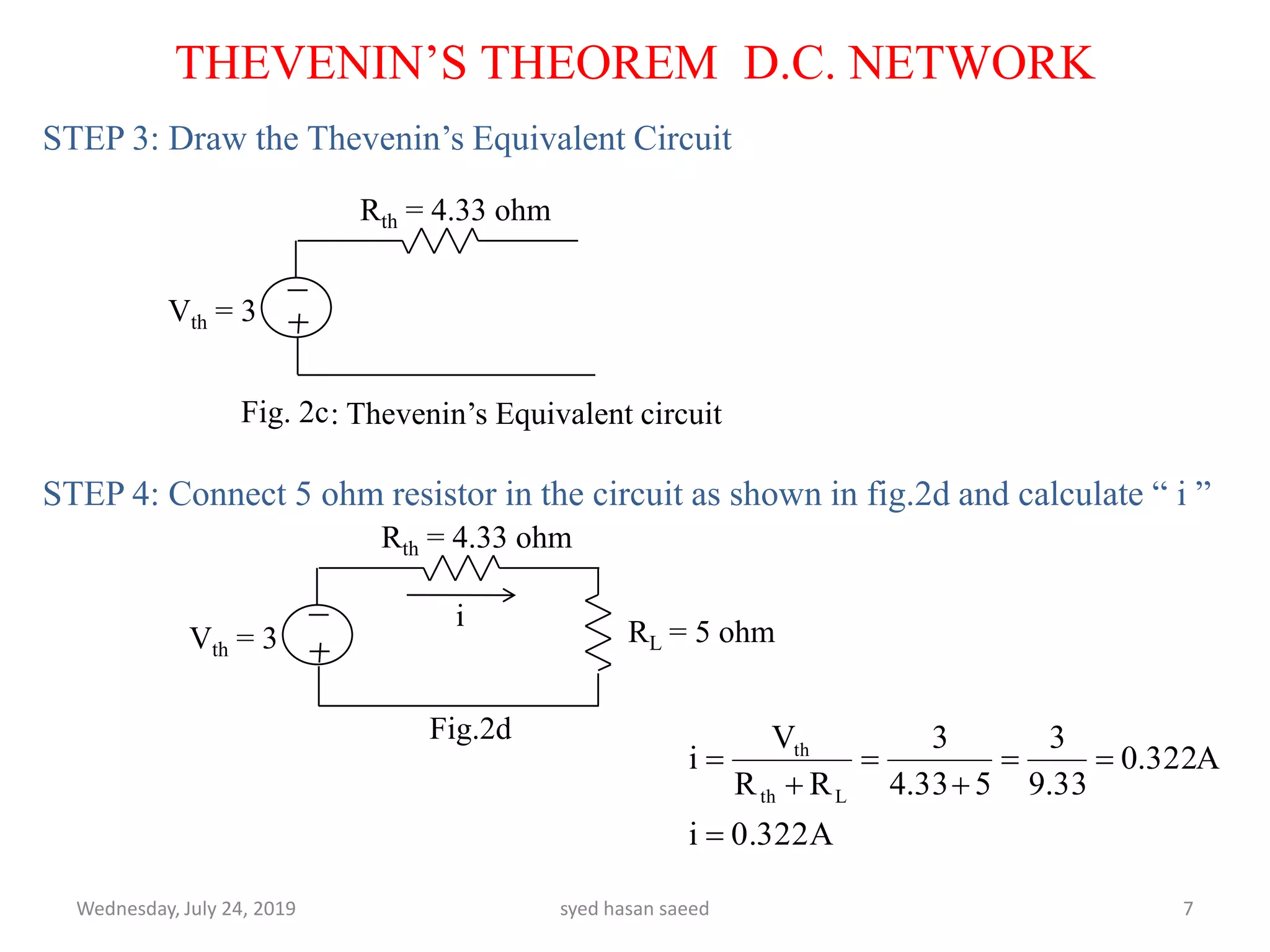
STEP 3: Draw the Thevenin’s Equivalent Circuit
STEP 4: Connect 5 ohm resistor in the circuit as shown in fig.2d and calculate “ i ”
Wednesday, July 24, 2019 syed hasan saeed 7
Vth = 3
Rth = 4.33 ohm
Fig. 2c
Vth = 3
Rth = 4.33 ohm
RL = 5 ohm
i
: Thevenin’s Equivalent circuit
Fig.2d
0.322Ai
A322.0
33.9
3
533.4
3
RR
V
i
Lth
th
8.
STEP 4: Calculationof Voltage drop across 5 ohm resistor :
STEP 5: Calculation of Power loss across 5 ohm resistor :
Wednesday, July 24, 2019 syed hasan saeed 8
THEVENIN’S THEOREM D.C. NETWORK
1.62V5*0.322R*iV5ohm
0.518w5*(0.322)R*(i)LossPower 22