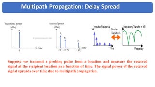
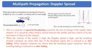
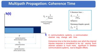
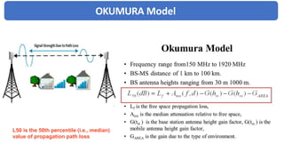
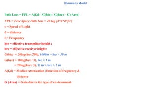
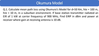
1. OKUMURA Model
• Radio transmission in a mobile communication system often takes place
over irregular terrain.
• The terrain profile of a particular area needs to taken in account for
estimating path loss.
• Presence of tree, budling, and other obstacles also must be taken into
account while estimating the path loss.
• Okumura model is one of the most widely used model for signal
prediction in urban area.
2. OKUMURA Model
L50 is the 50th percentile (i.e., median)
value of propagation path loss
3. Okumura Model
Path Loss = FPL + A(f,d) - G(hte) - G(hre) – G (Area)
FPL = Free Space Path Loss = 20 log {4*π*d*f/c}
c = Speed of Light
d = distance
f = Frequency
hte = effective transmitter height ;
hre = effective receiver height;
G(hte) = 20log(hte /200), 1000m > hte > 30 m
G(hre) = 10log(hre / 3), hre < 3 m
= 20log(hre / 3), 10 m > hre > 3 m
A(f,d) = MedianAttenuation :function of frequency &
distance
G (Area) = Gain due to the type of environment.
4. Okumura Model
Q.1. Calculate mean path loss using Okumura's Model for d=50 Km, hte = 100 m,
hre = 10 m, in a suburban environment. If base station transmitter radiated an
EIR of 1 kW at carrier frequency of 900 MHz, Find EIRP in dBm and power at
receiver where gain at receiving antenna is 10 dB.
8. Okumura Model
Disadvantage
The major disadvantage of Okumura
model is its slow response to rapid
changes in terrain, therefore the model is
good in urban and suburban areas but not
good in rural areas
9. Hata Model
• The Hata model is the empirical formulation of the graphical path
loss data provided by Okumura and valid from 150 MHz to 1.5 GHz.
• Although, Hata’s model does not have any of the path specific
corrections which are available in Okumura model.
• Prediction of Hata’s model compare very closely with the original
Okumura model as long as d exceeds 1 km.
10. Path Loss in Urban areas is given by
Path Loss = 69.55 + 26.16*log(f) - 13.82*log(hte) -a(hre) +(44.9-6.55*log(hte)*log(d)
Where:
f = Frequency (in MHz) from 150 MHz to 1500 MHz
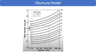
hte = Effective Transmitter Height, from 30 to 200 meters
hre = Effective Receiver Height, from 1m to 10 meters.
d = Transmitter - Receiver separation (in Km)
a(hre) = Correction factor for effective mobile antenna height, which is a function of the size of the coverage area.
=(1.1*log f - 0.7)hre -(1.56*log f - 0.8) dB For medium sized city
For large city
For large city
=8.29(log1.54hre)2 - 1.1 dB; where f <= 300 MHz
=3.2(log11.75hre)2 - 4.97 dB; where f>= 300 MHz
Path Loss in SuburbanAreas
Path Loss (Suburban) = Path Loss (Urban) -2*[log(f/28)]2 - 5.4
Path Loss for Open RuralAreas
Path Loss(Open Suburban) = Path Loss (Urban) - 4.78(log f )2 +18.33*(log f) - 40.94
Hata Model
11. Multipath Propagation: Delay Spread
Suppose we transmit a probing pulse from a location and measure the received
signal at the recipient location as a function of time. The signal power of the received
signal spreads over time due to multipath propagation.
12. Multipath Propagation: Doppler Spread
• This is a measure of spectral broadening caused by the rate of change of the mobile radio
channel. It is caused by either relative motion between the mobile and base station or by the
movement of objects in the channel.
• When the velocity of the mobile is high, the Doppler spread is high, and the resulting
channel variations are faster than that of the baseband signal, this is referred to as fast
fading. When channel variations are slower than the baseband signal variations, then the
resulting fading is referred to as slow fading.
13. Multipath Propagation: Coherence Time
In communications systems, a communication
channel may change with time.
Coherence time is the time duration over which the channel
impulse response is considered to be not varying. Such
channel variation is much more significant in wireless
communications systems, due to Doppler effects.
t
h(t)