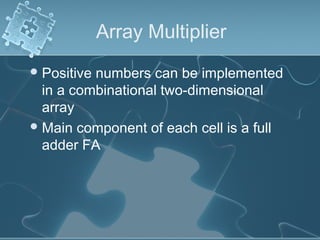
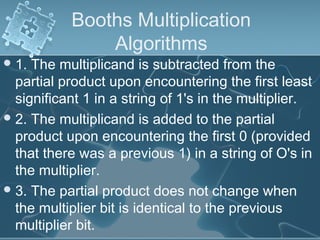
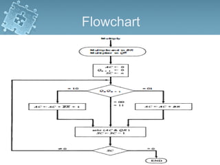
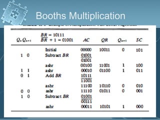
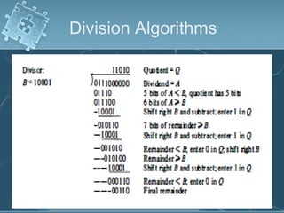
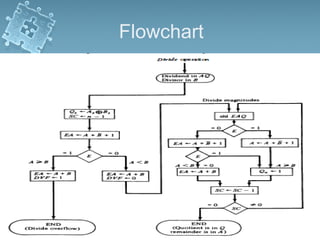
1) There are several algorithms for performing multiplication and division with signed-magnitude numbers, including array multiplication, Booth's multiplication, restoring division, and non-restoring division.
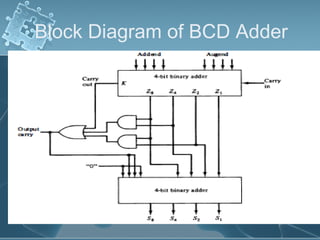
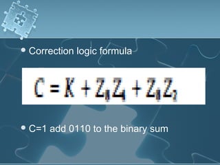
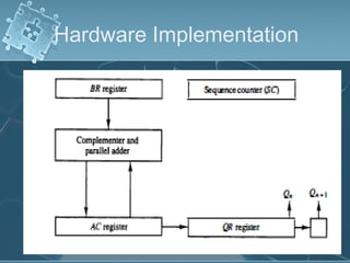
2) Hardware implementations of these algorithms often involve adders, shifters, and correction logic to handle issues like overflow and producing results in the proper number format.
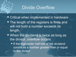
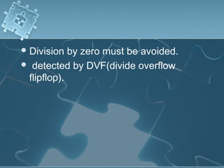
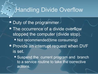
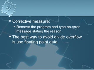
3) Division algorithms in particular require handling issues like division by zero and divide overflow through detection logic and interrupt-driven error handling.