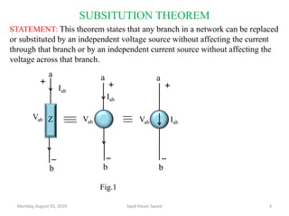
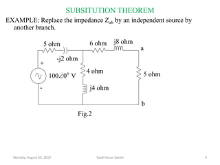
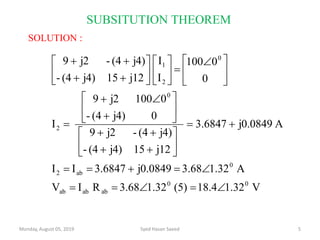
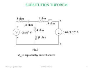
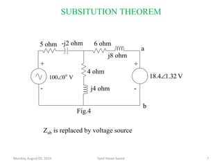
In electrical engineering, the maximum power transfer theorem states that, to obtain maximum external power from a source with a finite internal resistance, the resistance of the load must equal the resistance of the source as viewed from its output terminals.
thevenin theorem.
SLIDE NUMBER 3 EXPLANATION OF THEOREM: it is possible to simplify any electrical circuit, no matter how complex, to an equivalent two-terminal circuit with just a single constant voltage source in series with a resistance (or impedance) connected to a load. SLIDE NUMBER 4 INVENTION STORY THE THEOREM WAS INDEPENDENTLY DERIVED IN 1853 BY THE GERMAN SCIENTIST HERMANN VON HELMHOLTZ. SLIDE NUMBER 5 EXPLANATION OF Thevenin’s equivalent circuit As far as the load resistor RL is concerned, any complex “one-port” network consisting of multiple resistive circuit elements and energy sources can be replaced by one single equivalent resistance Rs and one single equivalent voltage Vs. Rs is the source resistance value looking back into the circuit and Vs is the open circuit voltage at the terminals. SLIDE NUMBER 6 EXPLANATION OF DIAGRAM 1
Let us consider a simple DC circuit as shown in the figure above, where we have to find the load current IL by the Thevenin’s theorem. In order to find the equivalent voltage source, rL is removed from the circuit as shown in the figure below and Voc or VTH is calculated. SLIDE NUMBER 7 EXPLANATION OF DIAGRAM 2
Now, to find the internal resistance of the network (Thevenin’s resistance or equivalent resistance) in series with the open circuit voltage VOC , also known as Thevenin’s voltage VTH, the voltage source is removed or we can say it is deactivated by a short circuit (as the source does not have any internal resistance) SLIDE NUMBER 9 As per Thevenin’s Statement, the load current is determined by the circuit shown above and the equivalent Thevenin’s circuit is obtained. Where, VTH is the Thevenin’s equivalent voltage. It is an open circuit voltage across the terminal AB known as load terminal RTH is the Thevenin’s equivalent resistance, as seen from the load terminals where all the sources are replaced by their internal impedance rL is the load resistance Steps for Solving Thevenin’s Theorem Step 1 – First of all remove the load resistance rL of the given circuit. Step 2 – Replace all the impedance source by their internal resistance. Step 3 – If sources are ideal then short circuit the voltage source and open the current source. Step 4 – Now find the equivalent resistance at the load terminals know as Thevenin’s Resistance (RTH). Step 5 – Draw the Thevenin’s equivalent circuit by connecting the load resistance and after that determine the desired response. Slide number-10 Thevenin Voltage The Thevenin voltage e used in Thevenin's Theorem is an ideal voltage source equal to the open circuit voltage at the terminals. In the example below, the resistance R2 does not affect this voltage and the resistances R1 and R3 form a voltage divider
Slide number-11 Thevinin resistance The Thevenin resistance r used in Thevenin's Theorem is the resistance measured at terminals AB with all voltage sources replaced by short circuits and all current sources replaced by open circuits.
As electric field, that is, force per unit charge is a vector quantity; it can be used to represent overall effect of electric field in system of electric charges. Similarly electric field can be used in pictorial form to describe the overall intensity of the field. Copy the link given below and paste it in new browser window to get more information on Electric Field Lines www.askiitians.com/iit-jee-electrostatics/electric-field-lines/
Electric power is the rate, per unit time, at which electrical energy is transferred by an electric circuit. The SI unit of power is the watt, one joule per second. Electric power is usually produced by electric generators, but can also be supplied by sources such as electric batteries. http://bit.ly/2PIOIQM
Sachpazis:Terzaghi Bearing Capacity Estimation in simple terms with Calculati...Dr.Costas Sachpazis
Terzaghi's soil bearing capacity theory, developed by Karl Terzaghi, is a fundamental principle in geotechnical engineering used to determine the bearing capacity of shallow foundations. This theory provides a method to calculate the ultimate bearing capacity of soil, which is the maximum load per unit area that the soil can support without undergoing shear failure. The Calculation HTML Code included.
Hierarchical Digital Twin of a Naval Power SystemKerry Sado
A hierarchical digital twin of a Naval DC power system has been developed and experimentally verified. Similar to other state-of-the-art digital twins, this technology creates a digital replica of the physical system executed in real-time or faster, which can modify hardware controls. However, its advantage stems from distributing computational efforts by utilizing a hierarchical structure composed of lower-level digital twin blocks and a higher-level system digital twin. Each digital twin block is associated with a physical subsystem of the hardware and communicates with a singular system digital twin, which creates a system-level response. By extracting information from each level of the hierarchy, power system controls of the hardware were reconfigured autonomously. This hierarchical digital twin development offers several advantages over other digital twins, particularly in the field of naval power systems. The hierarchical structure allows for greater computational efficiency and scalability while the ability to autonomously reconfigure hardware controls offers increased flexibility and responsiveness. The hierarchical decomposition and models utilized were well aligned with the physical twin, as indicated by the maximum deviations between the developed digital twin hierarchy and the hardware.
NO1 Uk best vashikaran specialist in delhi vashikaran baba near me online vas...Amil Baba Dawood bangali
Contact with Dawood Bhai Just call on +92322-6382012 and we'll help you. We'll solve all your problems within 12 to 24 hours and with 101% guarantee and with astrology systematic. If you want to take any personal or professional advice then also you can call us on +92322-6382012 , ONLINE LOVE PROBLEM & Other all types of Daily Life Problem's.Then CALL or WHATSAPP us on +92322-6382012 and Get all these problems solutions here by Amil Baba DAWOOD BANGALI
#vashikaranspecialist #astrologer #palmistry #amliyaat #taweez #manpasandshadi #horoscope #spiritual #lovelife #lovespell #marriagespell#aamilbabainpakistan #amilbabainkarachi #powerfullblackmagicspell #kalajadumantarspecialist #realamilbaba #AmilbabainPakistan #astrologerincanada #astrologerindubai #lovespellsmaster #kalajaduspecialist #lovespellsthatwork #aamilbabainlahore#blackmagicformarriage #aamilbaba #kalajadu #kalailam #taweez #wazifaexpert #jadumantar #vashikaranspecialist #astrologer #palmistry #amliyaat #taweez #manpasandshadi #horoscope #spiritual #lovelife #lovespell #marriagespell#aamilbabainpakistan #amilbabainkarachi #powerfullblackmagicspell #kalajadumantarspecialist #realamilbaba #AmilbabainPakistan #astrologerincanada #astrologerindubai #lovespellsmaster #kalajaduspecialist #lovespellsthatwork #aamilbabainlahore #blackmagicforlove #blackmagicformarriage #aamilbaba #kalajadu #kalailam #taweez #wazifaexpert #jadumantar #vashikaranspecialist #astrologer #palmistry #amliyaat #taweez #manpasandshadi #horoscope #spiritual #lovelife #lovespell #marriagespell#aamilbabainpakistan #amilbabainkarachi #powerfullblackmagicspell #kalajadumantarspecialist #realamilbaba #AmilbabainPakistan #astrologerincanada #astrologerindubai #lovespellsmaster #kalajaduspecialist #lovespellsthatwork #aamilbabainlahore #Amilbabainuk #amilbabainspain #amilbabaindubai #Amilbabainnorway #amilbabainkrachi #amilbabainlahore #amilbabaingujranwalan #amilbabainislamabad
Welcome to WIPAC Monthly the magazine brought to you by the LinkedIn Group Water Industry Process Automation & Control.
In this month's edition, along with this month's industry news to celebrate the 13 years since the group was created we have articles including
A case study of the used of Advanced Process Control at the Wastewater Treatment works at Lleida in Spain
A look back on an article on smart wastewater networks in order to see how the industry has measured up in the interim around the adoption of Digital Transformation in the Water Industry.
Explore the innovative world of trenchless pipe repair with our comprehensive guide, "The Benefits and Techniques of Trenchless Pipe Repair." This document delves into the modern methods of repairing underground pipes without the need for extensive excavation, highlighting the numerous advantages and the latest techniques used in the industry.
Learn about the cost savings, reduced environmental impact, and minimal disruption associated with trenchless technology. Discover detailed explanations of popular techniques such as pipe bursting, cured-in-place pipe (CIPP) lining, and directional drilling. Understand how these methods can be applied to various types of infrastructure, from residential plumbing to large-scale municipal systems.
Ideal for homeowners, contractors, engineers, and anyone interested in modern plumbing solutions, this guide provides valuable insights into why trenchless pipe repair is becoming the preferred choice for pipe rehabilitation. Stay informed about the latest advancements and best practices in the field.
2. REFERENCE BOOKS
• Introductory Circuit Analysis, Robert L. Boylested, Pearson Education,
Prentice Hall.
• Networks And Systems, Ashfaq Husain, Khanna Book Publishing Co (P)
Ltd. Delhi.
• Networks And Systems, A Sudhakr, Shyammohan S Palli, Tata McGraw
Hill, New Delhi.
• Network Analysis, M.E. Van Valkenburg, PHI Learning Private limited,
New Delhi.
• Circuit Analysis Principle and Applications, Allan H. Robbins &Wilhelm
C. Miller, DELMAR CENGAGE Learning, Indian Reprint.
Monday, August 05, 2019 syed hasan saeed 2
3. SUBSITUTION THEOREM
STATEMENT: This theorem states that any branch in a network can be replaced
or substituted by an independent voltage source without affecting the current
through that branch or by an independent current source without affecting the
voltage across that branch.
Monday, August 05, 2019 3Syed Hasan Saeed
a
b
Vab
Iab
Z
Iab
Vab
a
b
IabVab
a
b
Fig.1
4. EXAMPLE: Replace the impedance Zab by an independent source by
another branch.
Monday, August 05, 2019 Syed Hasan Saeed 4
SUBSITUTION THEOREM
5 ohm
-j2 ohm
6 ohm j8 ohm
5 ohm
j4 ohm
4 ohm
+
-
V0100 0
Fig.2
a
b