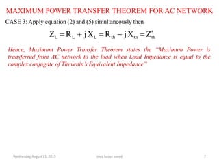
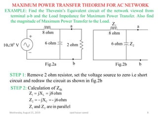
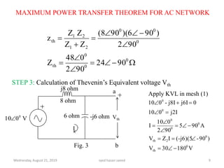
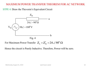
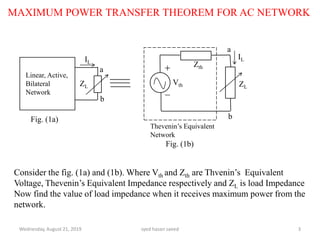
This document discusses the maximum power transfer theorem for AC networks. It defines the theorem as stating that maximum power is transferred from an AC network to a load when the load impedance is equal to the complex conjugate of the Thevenin's equivalent impedance of the network. It provides examples of calculating the Thevenin's equivalent circuit for a given network and determining the load impedance required for maximum power transfer. In the example network shown, the Thevenin's equivalent impedance is found to be purely inductive, meaning no power can be transferred to the load.
In electrical engineering, the maximum power transfer theorem states that, to obtain maximum external power from a source with a finite internal resistance, the resistance of the load must equal the resistance of the source as viewed from its output terminals.
Explaining about one of the popular theorems in electrical engineering, Thevenin's theorem. it gives direct idea about the theorem and its different cases of applicability. Some of easy tricks and facts are also included for convenience.
thevenin theorem.
SLIDE NUMBER 3 EXPLANATION OF THEOREM: it is possible to simplify any electrical circuit, no matter how complex, to an equivalent two-terminal circuit with just a single constant voltage source in series with a resistance (or impedance) connected to a load. SLIDE NUMBER 4 INVENTION STORY THE THEOREM WAS INDEPENDENTLY DERIVED IN 1853 BY THE GERMAN SCIENTIST HERMANN VON HELMHOLTZ. SLIDE NUMBER 5 EXPLANATION OF Thevenin’s equivalent circuit As far as the load resistor RL is concerned, any complex “one-port” network consisting of multiple resistive circuit elements and energy sources can be replaced by one single equivalent resistance Rs and one single equivalent voltage Vs. Rs is the source resistance value looking back into the circuit and Vs is the open circuit voltage at the terminals. SLIDE NUMBER 6 EXPLANATION OF DIAGRAM 1
Let us consider a simple DC circuit as shown in the figure above, where we have to find the load current IL by the Thevenin’s theorem. In order to find the equivalent voltage source, rL is removed from the circuit as shown in the figure below and Voc or VTH is calculated. SLIDE NUMBER 7 EXPLANATION OF DIAGRAM 2
Now, to find the internal resistance of the network (Thevenin’s resistance or equivalent resistance) in series with the open circuit voltage VOC , also known as Thevenin’s voltage VTH, the voltage source is removed or we can say it is deactivated by a short circuit (as the source does not have any internal resistance) SLIDE NUMBER 9 As per Thevenin’s Statement, the load current is determined by the circuit shown above and the equivalent Thevenin’s circuit is obtained. Where, VTH is the Thevenin’s equivalent voltage. It is an open circuit voltage across the terminal AB known as load terminal RTH is the Thevenin’s equivalent resistance, as seen from the load terminals where all the sources are replaced by their internal impedance rL is the load resistance Steps for Solving Thevenin’s Theorem Step 1 – First of all remove the load resistance rL of the given circuit. Step 2 – Replace all the impedance source by their internal resistance. Step 3 – If sources are ideal then short circuit the voltage source and open the current source. Step 4 – Now find the equivalent resistance at the load terminals know as Thevenin’s Resistance (RTH). Step 5 – Draw the Thevenin’s equivalent circuit by connecting the load resistance and after that determine the desired response. Slide number-10 Thevenin Voltage The Thevenin voltage e used in Thevenin's Theorem is an ideal voltage source equal to the open circuit voltage at the terminals. In the example below, the resistance R2 does not affect this voltage and the resistances R1 and R3 form a voltage divider
Slide number-11 Thevinin resistance The Thevenin resistance r used in Thevenin's Theorem is the resistance measured at terminals AB with all voltage sources replaced by short circuits and all current sources replaced by open circuits.
Presentation about chapter 1 of electrical circuit analysis. standard prefixes. basic terminology power,current,voltage,resistance.How power is absorbed by the circuit and its calculation with passive sign convention.
Ekeeda Provides Online Electrical and Electronics Engineering Degree Subjects Courses, Video Lectures for All Engineering Universities. Video Tutorials Covers Subjects of Mechanical Engineering Degree.
Distribution System Voltage Drop and Power Loss CalculationAmeen San
Distribution System Voltage Drop and Power Loss
Calculation
Comparison of Overhead Versus Underground System
Power Loss Calculation,Voltage Drop Calculation
Reactive Power Compensation and Control via Shunt Reactors and Under Ground P...IJERA Editor
In this paper we will cover the techniques used locally to accomplish the reactive power compensation. First, the importance of reactive power compensation is explained through defining the different types of electrical power and showing the effect of power compensation on the electric power network quality. The power under ground cable is the first technique used to compensate for the inductance of overhead transmission lines and power transformers during heavy loading of the network. Then, we explore the application of the two types of shunt reactors in different locations of the network to compensate for the capacitance of the network during light loading. Finally, a conclusion is presented.
In this research paper total harmonic
distortion of three phase supply system (half and full
wave) AC/DC converter-fed with DC motor load is
analyzed ,using both simulation and experimental
arrangements, it is keenly important to analyze
harmonic contents, because of harmonics injection has
very bad effects in electrical power system and the
overall efficiency of the system becomes low, which
results poor power quality, current and voltage
distortion and at input AC mains power factor becomes
also low. [4] In this research work we have proposed
three phase full wave AC-DC converter topology which
is better for energy conversion as compared to three
phase half wave AC-DC converter topology ,using
MATLAB /simulation as well as from the experimentaly
performed setup, it was found that DC motor efficiency
for three phase full wave rectified-fed is better as
compared to three phase half wave rectified-fed.
Integrated Circuitry For Better Energy Transfer Through Resonant Couplingijceronline
International Journal of Computational Engineering Research (IJCER) is dedicated to protecting personal information and will make every reasonable effort to handle collected information appropriately. All information collected, as well as related requests, will be handled as carefully and efficiently as possible in accordance with IJCER standards for integrity and objectivity.
Power Flow Analysis for Four Buses System by NR Methodijtsrd
Power flow studies provide a systematic mathematical approach for determination of various bus voltages, there phase angle, active and reactive power flows through different branches, generators and loads under steady state condition. In this paper, the purpose of power flow analysis is to determine four bus system power flows. Case studies have been performed on Lawpita Taungoo Kamarnat Hlawga 230kV Line Myanmar . This paper presents a reliable method to meet the requirements by developing a Newton Raphson based load flow calculation program through which control setting of Shunt Compensator can be determined directly. This program computes the voltage magnitude and angle at each bus in a power system under balanced steady state conditions. Real and reactive power flows for all buses, as well as line flow and line losses, are also computed. And then the compensation of shunt capacitor is proposed for load flow analysis and also for overall loss minimization and improvement in system voltage profile. Wint Yu Yu Zaw ""Power Flow Analysis for Four Buses System by NR Method"" Published in International Journal of Trend in Scientific Research and Development (ijtsrd), ISSN: 2456-6470, Volume-3 | Issue-3 , April 2019, URL: https://www.ijtsrd.com/papers/ijtsrd23472.pdf
Paper URL: https://www.ijtsrd.com/engineering/electronics-and-communication-engineering/23472/power-flow-analysis-for-four-buses-system-by-nr-method/wint-yu-yu-zaw
Lab 5 BASIC CIRCUITS( Resistors, Voltage,and Current with.docxfestockton
Lab 5: BASIC CIRCUITS
( Resistors, Voltage,
and Current with MATLAB adapted from P-178 DC Circuit Labs )
Introduction
:
Electric circuits can be defined as closed or continuous paths in which electric currents are confined and around which electric currents can be caused to flow. Electrical circuits are an essential part of daily living, and may be found in heavy and light industry, commercial installations and operations, and residential applications. Modern life and its many conveniences seem inconceivable without the use of electric circuits.
The total resistance of a circuit is the sum of the individual resistances of the power source, the wiring, and the load. The load resistance is generally much higher than either the resistance of the power source or the wiring. The resistances of the wiring are usually neglected in classroom laboratory experiments. Very rarely is circuit wiring significant in experimental work. In these cases we consider the loads resistances to be the only resistance. Wiring resistance may be considerable in the case of transmission cables, as well as telephone lines, which are many miles long, and we have a lab which investigates and calculates the resistance in such cables and the lost power and energy due to these lengths.
If an arbitrary load of relatively low resistance were connected to an existing power supply or voltage source, an excessive current might flow to the load, causing burn up or other malfunctions with the load and wiring.
The current can be reduced
by reducing the source voltage, but this is not always feasible and is frequently impossible. The resistances of the voltage source or the load could be increased, but these are usually built right into the source or load. Resistances of connecting wires are so low that miles would be needed to increase the circuit resistance by more than a few dozen ohms. A selection of materials for connecting wires might be useful, but a better method would be to creation of a device that is specifically a resistor that can be included with the circuit to give the net or total resistance needed to provide the desired current for the voltage source involved.
In any DC circuit, the total current is equal to the power source voltage divided by the total or equivalent resistance. For a Series Circuit, this is the only current. This means that if the current in some portion of the circuit is known, the total current and the current through every part of the circuit is known. The sum of the voltage drops across the resistors in series is equal to the power supply voltage.
In Parallel Circuits, the total current from the power source divides into different paths as in approaches the parallel branches. The voltage drop across parallel branches is the same for all the branches. If the voltage drop for one branch is known, the voltage drop for all the parallel branches is known.
The sum of the currents in the various branches is equal to the current from the po.
A Narrative Approach to Five Phase Transmission SystemIJMTST Journal
The power demand is increasing day to day and is becoming prime requirement. High Phase Order (HPO)
transmission system is being considered a viable alternative to meet the demand by increasing the power
transmission capability. Mainly the research of HPO systems is going on six and twelve phase transmission
systems since they are multiples of three. But there is no difference in magnitude between the line voltage
and phase voltage. This paper takes the instigation regarding Five Phase transmission system and results
are compared with 132 kV three phase system. This paper investigates the weight of the conductor, sag of
the conductor and spacing between the conductors, Inductance and capacitance calculations required in 132
kV Five Phase transmission system. Also, shows the line model of Five Phase transmission system. So,
industrial loads can be driven with Five Phase supply as a ripple free torque and efficiency will be increased
effectively.
Design of wireless power transfer system via magnetic resonant coupling at 13...Ajay Kumar Sah
Design of Wireless Power Transfer System via Magnetic Resonant Coupling at 13.56MHz
Abstract: Power is a must to modern systems. Power transmission through wires is common. But not in every field can wires be used because of certain limitations. The implantable biomedical devices like pacemakers, cardiac defibrillators, and artificial hearts require power supply for long term operation. The required power is supplied by driveline cable or by battery. WPT greatly reduces the risk of infection by eliminating the driveline cable which otherwise needs to puncture the skin to provide power and also saves the valuable space inside a person’s body in case of battery powered. In such fields, what we need is wireless transmission. Wireless transmission is useful in cases where instantaneous or continuous energy transfer is needed, but interconnecting wires are inconvenient, hazardous, or impossible. In this paper, a simple design method of a wireless power transfer system using 13.56 MHz ISM band is proposed. The proposed wireless power transfer system consists of rectifier, oscillator, power amplifier, power coil, load coil and two intermediate coils as transmitter antenna and receiver antenna inserted between power coil and load coil.
WIRELESS POWER TRANSFER - A TECHNOLOGY THAT HAS COME OF AGEIAEME Publication
Wireless power transfer has its roots in Tesla’s experiments and his proposition that electric power can be transferred not only by means of radiation, but also by means of induction and resonant coupling. Recent trends in the development of this technology are addressed. Also the basic mathematical ideas that help us understand the various parameters and issues for optimization of power transfer are given. The power in a given load in case of two coils is compared with that obtained in a modified set up consisting of three coils and it is shown that by proper choice of coupling coefficients, one might improvise the existing methods.
OPTIMIZATION OF A TWO-HOP NETWORK WITH ENERGY CONFERENCING RELAYSijwmn
This paper considers a two-hop network consisting of a source, two parallel half-duplex relay nodes, and
two destinations. While the destinations have an adequate power supply, the source and relay nodes
rely on harvested energy for data transmission. Different from all existing works, the two relay nodes
can also transfer their harvested energy to each other. For such a system, an optimization problem is
formulated with the objective of maximizing the total data rate and conserving the source and relays
transmission energy, where any extra energy saved in the current transmission cycle can be used in
the next cycle. It turns out that the optimal solutions for this problem can be either found in a closedform
or through one-dimensional searches, depending on the scenario. Simulation results based on both
the average data rate and the outage probability show that energy cooperation between the two relays
consistently improves the system performance.
Similar to Maximum power transfer theorem for ac network (20)
About
Indigenized remote control interface card suitable for MAFI system CCR equipment. Compatible for IDM8000 CCR. Backplane mounted serial and TCP/Ethernet communication module for CCR remote access. IDM 8000 CCR remote control on serial and TCP protocol.
• Remote control: Parallel or serial interface.
• Compatible with MAFI CCR system.
• Compatible with IDM8000 CCR.
• Compatible with Backplane mount serial communication.
• Compatible with commercial and Defence aviation CCR system.
• Remote control system for accessing CCR and allied system over serial or TCP.
• Indigenized local Support/presence in India.
• Easy in configuration using DIP switches.
Technical Specifications
Indigenized remote control interface card suitable for MAFI system CCR equipment. Compatible for IDM8000 CCR. Backplane mounted serial and TCP/Ethernet communication module for CCR remote access. IDM 8000 CCR remote control on serial and TCP protocol.
Key Features
Indigenized remote control interface card suitable for MAFI system CCR equipment. Compatible for IDM8000 CCR. Backplane mounted serial and TCP/Ethernet communication module for CCR remote access. IDM 8000 CCR remote control on serial and TCP protocol.
• Remote control: Parallel or serial interface
• Compatible with MAFI CCR system
• Copatiable with IDM8000 CCR
• Compatible with Backplane mount serial communication.
• Compatible with commercial and Defence aviation CCR system.
• Remote control system for accessing CCR and allied system over serial or TCP.
• Indigenized local Support/presence in India.
Application
• Remote control: Parallel or serial interface.
• Compatible with MAFI CCR system.
• Compatible with IDM8000 CCR.
• Compatible with Backplane mount serial communication.
• Compatible with commercial and Defence aviation CCR system.
• Remote control system for accessing CCR and allied system over serial or TCP.
• Indigenized local Support/presence in India.
• Easy in configuration using DIP switches.
NO1 Uk best vashikaran specialist in delhi vashikaran baba near me online vas...Amil Baba Dawood bangali
Contact with Dawood Bhai Just call on +92322-6382012 and we'll help you. We'll solve all your problems within 12 to 24 hours and with 101% guarantee and with astrology systematic. If you want to take any personal or professional advice then also you can call us on +92322-6382012 , ONLINE LOVE PROBLEM & Other all types of Daily Life Problem's.Then CALL or WHATSAPP us on +92322-6382012 and Get all these problems solutions here by Amil Baba DAWOOD BANGALI
#vashikaranspecialist #astrologer #palmistry #amliyaat #taweez #manpasandshadi #horoscope #spiritual #lovelife #lovespell #marriagespell#aamilbabainpakistan #amilbabainkarachi #powerfullblackmagicspell #kalajadumantarspecialist #realamilbaba #AmilbabainPakistan #astrologerincanada #astrologerindubai #lovespellsmaster #kalajaduspecialist #lovespellsthatwork #aamilbabainlahore#blackmagicformarriage #aamilbaba #kalajadu #kalailam #taweez #wazifaexpert #jadumantar #vashikaranspecialist #astrologer #palmistry #amliyaat #taweez #manpasandshadi #horoscope #spiritual #lovelife #lovespell #marriagespell#aamilbabainpakistan #amilbabainkarachi #powerfullblackmagicspell #kalajadumantarspecialist #realamilbaba #AmilbabainPakistan #astrologerincanada #astrologerindubai #lovespellsmaster #kalajaduspecialist #lovespellsthatwork #aamilbabainlahore #blackmagicforlove #blackmagicformarriage #aamilbaba #kalajadu #kalailam #taweez #wazifaexpert #jadumantar #vashikaranspecialist #astrologer #palmistry #amliyaat #taweez #manpasandshadi #horoscope #spiritual #lovelife #lovespell #marriagespell#aamilbabainpakistan #amilbabainkarachi #powerfullblackmagicspell #kalajadumantarspecialist #realamilbaba #AmilbabainPakistan #astrologerincanada #astrologerindubai #lovespellsmaster #kalajaduspecialist #lovespellsthatwork #aamilbabainlahore #Amilbabainuk #amilbabainspain #amilbabaindubai #Amilbabainnorway #amilbabainkrachi #amilbabainlahore #amilbabaingujranwalan #amilbabainislamabad
Immunizing Image Classifiers Against Localized Adversary Attacksgerogepatton
This paper addresses the vulnerability of deep learning models, particularly convolutional neural networks
(CNN)s, to adversarial attacks and presents a proactive training technique designed to counter them. We
introduce a novel volumization algorithm, which transforms 2D images into 3D volumetric representations.
When combined with 3D convolution and deep curriculum learning optimization (CLO), itsignificantly improves
the immunity of models against localized universal attacks by up to 40%. We evaluate our proposed approach
using contemporary CNN architectures and the modified Canadian Institute for Advanced Research (CIFAR-10
and CIFAR-100) and ImageNet Large Scale Visual Recognition Challenge (ILSVRC12) datasets, showcasing
accuracy improvements over previous techniques. The results indicate that the combination of the volumetric
input and curriculum learning holds significant promise for mitigating adversarial attacks without necessitating
adversary training.
Hybrid optimization of pumped hydro system and solar- Engr. Abdul-Azeez.pdffxintegritypublishin
Advancements in technology unveil a myriad of electrical and electronic breakthroughs geared towards efficiently harnessing limited resources to meet human energy demands. The optimization of hybrid solar PV panels and pumped hydro energy supply systems plays a pivotal role in utilizing natural resources effectively. This initiative not only benefits humanity but also fosters environmental sustainability. The study investigated the design optimization of these hybrid systems, focusing on understanding solar radiation patterns, identifying geographical influences on solar radiation, formulating a mathematical model for system optimization, and determining the optimal configuration of PV panels and pumped hydro storage. Through a comparative analysis approach and eight weeks of data collection, the study addressed key research questions related to solar radiation patterns and optimal system design. The findings highlighted regions with heightened solar radiation levels, showcasing substantial potential for power generation and emphasizing the system's efficiency. Optimizing system design significantly boosted power generation, promoted renewable energy utilization, and enhanced energy storage capacity. The study underscored the benefits of optimizing hybrid solar PV panels and pumped hydro energy supply systems for sustainable energy usage. Optimizing the design of solar PV panels and pumped hydro energy supply systems as examined across diverse climatic conditions in a developing country, not only enhances power generation but also improves the integration of renewable energy sources and boosts energy storage capacities, particularly beneficial for less economically prosperous regions. Additionally, the study provides valuable insights for advancing energy research in economically viable areas. Recommendations included conducting site-specific assessments, utilizing advanced modeling tools, implementing regular maintenance protocols, and enhancing communication among system components.
Hierarchical Digital Twin of a Naval Power SystemKerry Sado
A hierarchical digital twin of a Naval DC power system has been developed and experimentally verified. Similar to other state-of-the-art digital twins, this technology creates a digital replica of the physical system executed in real-time or faster, which can modify hardware controls. However, its advantage stems from distributing computational efforts by utilizing a hierarchical structure composed of lower-level digital twin blocks and a higher-level system digital twin. Each digital twin block is associated with a physical subsystem of the hardware and communicates with a singular system digital twin, which creates a system-level response. By extracting information from each level of the hierarchy, power system controls of the hardware were reconfigured autonomously. This hierarchical digital twin development offers several advantages over other digital twins, particularly in the field of naval power systems. The hierarchical structure allows for greater computational efficiency and scalability while the ability to autonomously reconfigure hardware controls offers increased flexibility and responsiveness. The hierarchical decomposition and models utilized were well aligned with the physical twin, as indicated by the maximum deviations between the developed digital twin hierarchy and the hardware.
Cosmetic shop management system project report.pdfKamal Acharya
Buying new cosmetic products is difficult. It can even be scary for those who have sensitive skin and are prone to skin trouble. The information needed to alleviate this problem is on the back of each product, but it's thought to interpret those ingredient lists unless you have a background in chemistry.
Instead of buying and hoping for the best, we can use data science to help us predict which products may be good fits for us. It includes various function programs to do the above mentioned tasks.
Data file handling has been effectively used in the program.
The automated cosmetic shop management system should deal with the automation of general workflow and administration process of the shop. The main processes of the system focus on customer's request where the system is able to search the most appropriate products and deliver it to the customers. It should help the employees to quickly identify the list of cosmetic product that have reached the minimum quantity and also keep a track of expired date for each cosmetic product. It should help the employees to find the rack number in which the product is placed.It is also Faster and more efficient way.
Explore the innovative world of trenchless pipe repair with our comprehensive guide, "The Benefits and Techniques of Trenchless Pipe Repair." This document delves into the modern methods of repairing underground pipes without the need for extensive excavation, highlighting the numerous advantages and the latest techniques used in the industry.
Learn about the cost savings, reduced environmental impact, and minimal disruption associated with trenchless technology. Discover detailed explanations of popular techniques such as pipe bursting, cured-in-place pipe (CIPP) lining, and directional drilling. Understand how these methods can be applied to various types of infrastructure, from residential plumbing to large-scale municipal systems.
Ideal for homeowners, contractors, engineers, and anyone interested in modern plumbing solutions, this guide provides valuable insights into why trenchless pipe repair is becoming the preferred choice for pipe rehabilitation. Stay informed about the latest advancements and best practices in the field.
Final project report on grocery store management system..pdfKamal Acharya
In today’s fast-changing business environment, it’s extremely important to be able to respond to client needs in the most effective and timely manner. If your customers wish to see your business online and have instant access to your products or services.
Online Grocery Store is an e-commerce website, which retails various grocery products. This project allows viewing various products available enables registered users to purchase desired products instantly using Paytm, UPI payment processor (Instant Pay) and also can place order by using Cash on Delivery (Pay Later) option. This project provides an easy access to Administrators and Managers to view orders placed using Pay Later and Instant Pay options.
In order to develop an e-commerce website, a number of Technologies must be studied and understood. These include multi-tiered architecture, server and client-side scripting techniques, implementation technologies, programming language (such as PHP, HTML, CSS, JavaScript) and MySQL relational databases. This is a project with the objective to develop a basic website where a consumer is provided with a shopping cart website and also to know about the technologies used to develop such a website.
This document will discuss each of the underlying technologies to create and implement an e- commerce website.
Final project report on grocery store management system..pdf
Maximum power transfer theorem for ac network
1. CIRCUIT THEORY
MAXIMUM POWER TRANSFER THEOREM
FOR
AC NETWORK
Wednesday, August 21, 2019 1syed hasan saeed
SYED HASAN SAEED
2. MAXIMUM POWER TRANSFER THEOREM FOR AC NETWORK
REFERENCE BOOKS
• Introductory Circuit Analysis, Robert L. Boylested, Pearson Education,
Prentice Hall.
• Networks And Systems, Ashfaq Husain, Khanna Book Publishing Co (P)
Ltd. Delhi.
• Networks And Systems, A Sudhakr, Shyammohan S Palli, Tata McGraw
Hill, New Delhi.
• Network Analysis, M.E. Van Valkenburg, PHI Learning Private limited,
New Delhi.
• Circuit Analysis Principle and Applications, Allan H. Robbins &Wilhelm
C. Miller, DELMAR CENGAGE Learning, Indian Reprint.
Wednesday, August 21, 2019 syed hasan saeed 2
3. Wednesday, August 21, 2019 syed hasan saeed 3
Vth
Zth
Linear, Active,
Bilateral
Network
a
b
b
a
IL
IL
Thevenin’s Equivalent
Network
Fig. (1a)
Fig. (1b)
ZL ZL
MAXIMUM POWER TRANSFER THEOREM FOR AC NETWORK
Consider the fig. (1a) and (1b). Where Vth and Zth are Thvenin’s Equivalent
Voltage, Thevenin’s Equivalent Impedance respectively and ZL is load Impedance
Now find the value of load impedance when it receives maximum power from the
network.
4. MAXIMUM POWER TRANSFER THEOREM FOR AC NETWORK
PROOF:
Wednesday, August 21, 2019 syed hasan saeed 4
2
Lth
2
Lth
th
L
LthLth
th
L
Lth
th
L
LLL
ththth
)X(X)R(R
V
I
)X(Xj)R(R
V
I
ZZ
V
I
jXRZ
jXRZ
Power Transferred to the load is
-(1)-------
)X(X)R(R
RV
RIP 2
Lth
2
Lth
L
2
th
L
2
LL
5. MAXIMUM POWER TRANSFER THEOREM FOR AC NETWORK
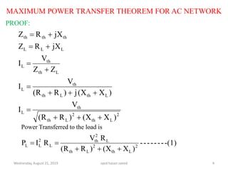
For any network Vth, Rth and Xth are fixed.
CASE 1: When RL is constant and XL is varying:
Wednesday, August 21, 2019 syed hasan saeed 5
(2)-----------X-X
0X2(XRV-
0
)X(X)R(R
X2(XRV-[0])X(X)R(R
dX
dP
0
)X(X)R(R
RV
dX
d
dX
dP
thL
ththL
2
th
22
Lth
2
Lth
LthL
2
th
2
Lth
2
Lth
L
L
2
Lth
2
Lth
L
2
th
LL
L
Hence, the magnitude of load reactance must be equal Thevenin’s reactance but
opposite phase difference. This is the first condition. The equation (1) becomes
)3(
)R(R
RV
P 2
Lth
L
2
th
L
6. MAXIMUM POWER TRANSFER THEOREM FOR AC NETWORK
CASE 2: When XL is constant and RL is varying
Wednesday, August 21, 2019 syed hasan saeed 6
(4)-------R)X(XR
0)R2(RRV-][V)X(X)R(R
0
)X(X)R(R
)R2(RRV-][V)X(X)R(R
dX
dP
0
)X(X)R(R
RV
dR
d
dR
dP
L
2
Lth
2
th
LthL
2
th
2
th
2
Lth
2
Lth
22
Lth
2
Lth
LthL
2
th
2
th
2
Lth
2
Lth
L
L
2
Lth
2
Lth
L
2
th
LL
L
Put Xth = -XL in equation (4)
RL = Rth - - - - - - - - - - - - - - - (5)
Hence, for maximum Power Transfer, the load resistance must be equal to the
Thevenin’s Equivalent Resistance. The equation (3) becomes
)6(
4R
V
P
th
2
th
maxL
7. MAXIMUM POWER TRANSFER THEOREM FOR AC NETWORK
CASE 3: Apply equation (2) and (5) simultaneously then
Wednesday, August 21, 2019 syed hasan saeed 7
thththLLL ZXjRXjRZ
Hence, Maximum Power Transfer Theorem states the “Maximum Power is
transferred from AC network to the load when Load Impedance is equal to the
complex conjugate of Thevenin’s Equivalent Impedance”
8. MAXIMUM POWER TRANSFER THEOREM FOR AC NETWORK
EXAMPLE: Find the Thevenin’s Equivalent circuit of the network viewed from
terminal a-b and the Load Impedance for Maximum Power Transfer. Also find
the magnitude of Maximum Power Transfer to the Load.
Wednesday, August 21, 2019 syed hasan saeed 8
V010 0
8 ohm
6 ohm 2 ohm
a
bFig.2a
STEP 1: Remove 2 ohm resistor, set the voltage source to zero i.e short
circuit and redraw the circuit as shown in fig.2b
STEP 2: Calculation of Zth
parallelinareZandZ
ohmj6-jXZ
ohmj8jXZ
21
C2
L1
8 ohm
6 ohm
b
a
Fig.2b
1Z
2Z
9. MAXIMUM POWER TRANSFER THEOREM FOR AC NETWORK
Wednesday, August 21, 2019 syed hasan saeed 9
0
0
0
th
0
00
21
21
th
9024
902
048
Z
902
)906)(90(8
ZZ
ZZ
z
STEP 3: Calculation of Thevenin’s Equivalent voltage Vth
8 ohm
6 ohm
a
b
V010 0
Vth
Apply KVL in mesh (1)
I
V18030V
)90-(-j6)(5IZV
A905
902
010
I
j2I010
0j6Ij8I-010
0
th
0
2th
0
0
0
0
0
Fig. 3
-j6 ohm
j8 ohm
10. MAXIMUM POWER TRANSFER THEOREM FOR AC NETWORK
STPE 4: Draw the Thevenin’s Equivalent Circuit
Hence the circuit is Purely Inductive. Therefore, Power will be zero.
Wednesday, August 21, 2019 syed hasan saeed 10
Vth
Zth
V18030 0
0
9024
a
b
Fig. 4
For Maximum Power Transfer
9024ZZ 0
thL
11. Wednesday, August 21, 2019 syed hasan saeed 11
THANK YOU
hasansaeedcontrol@gmail.com
shasansaeed@yolasite.com
hasansaeed872726549.wordpress.com
saeed.moodlecloud.com
syedhasansaeed.gnomio.com