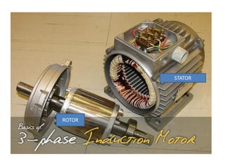
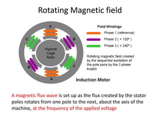
1. Three phase induction motors have a rotating magnetic field produced by a three phase stator winding that causes the rotor to turn.
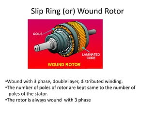
2. The rotor can be either a squirrel cage (copper or aluminum bars short circuited by end rings) or wound construction.
3. Starters are used to reduce the starting current by lowering the supply voltage and improve starting torque by increasing rotor resistance during start up. Common starting methods include direct-on-line, star-delta, and auto transformer starters.