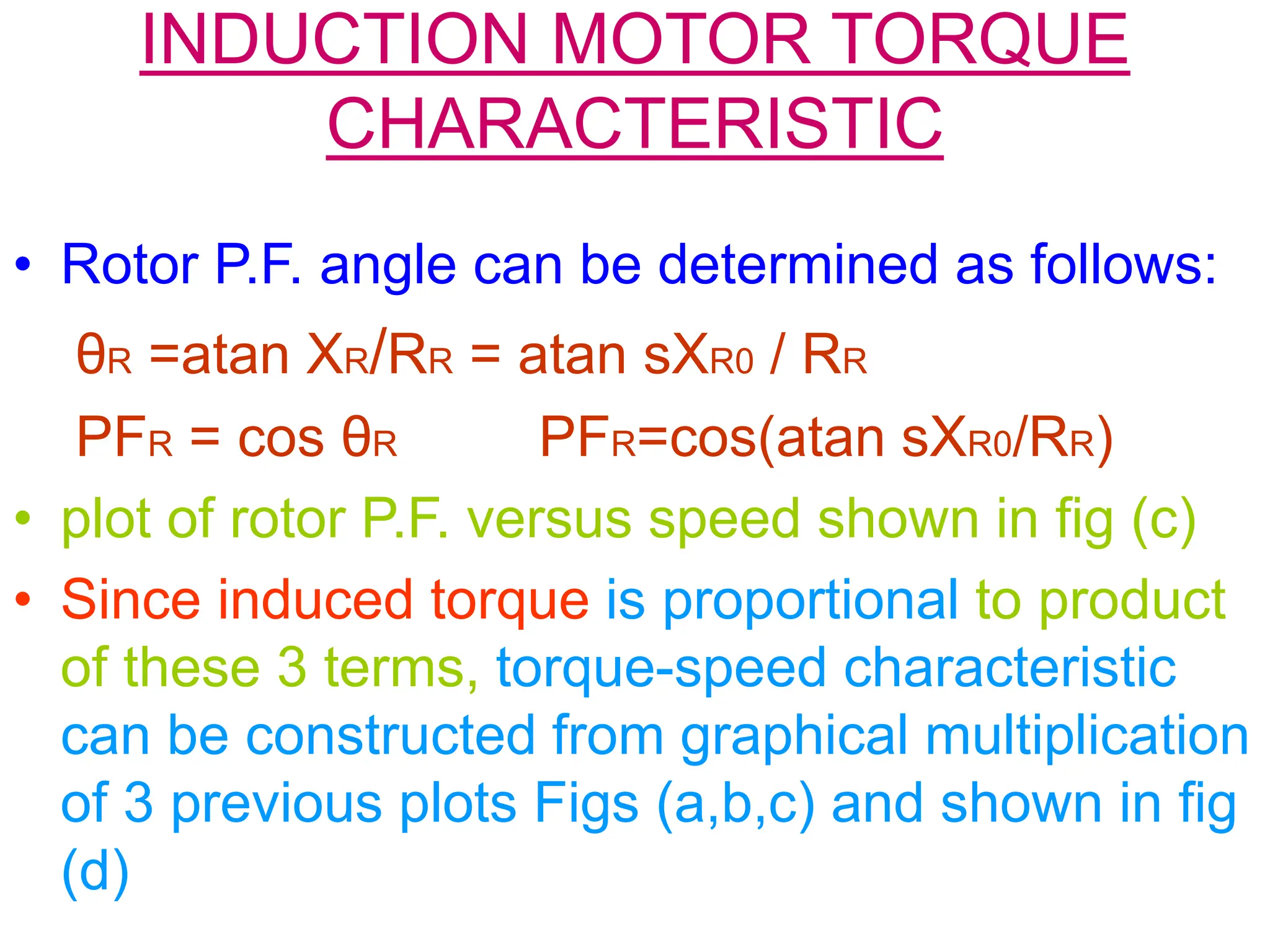
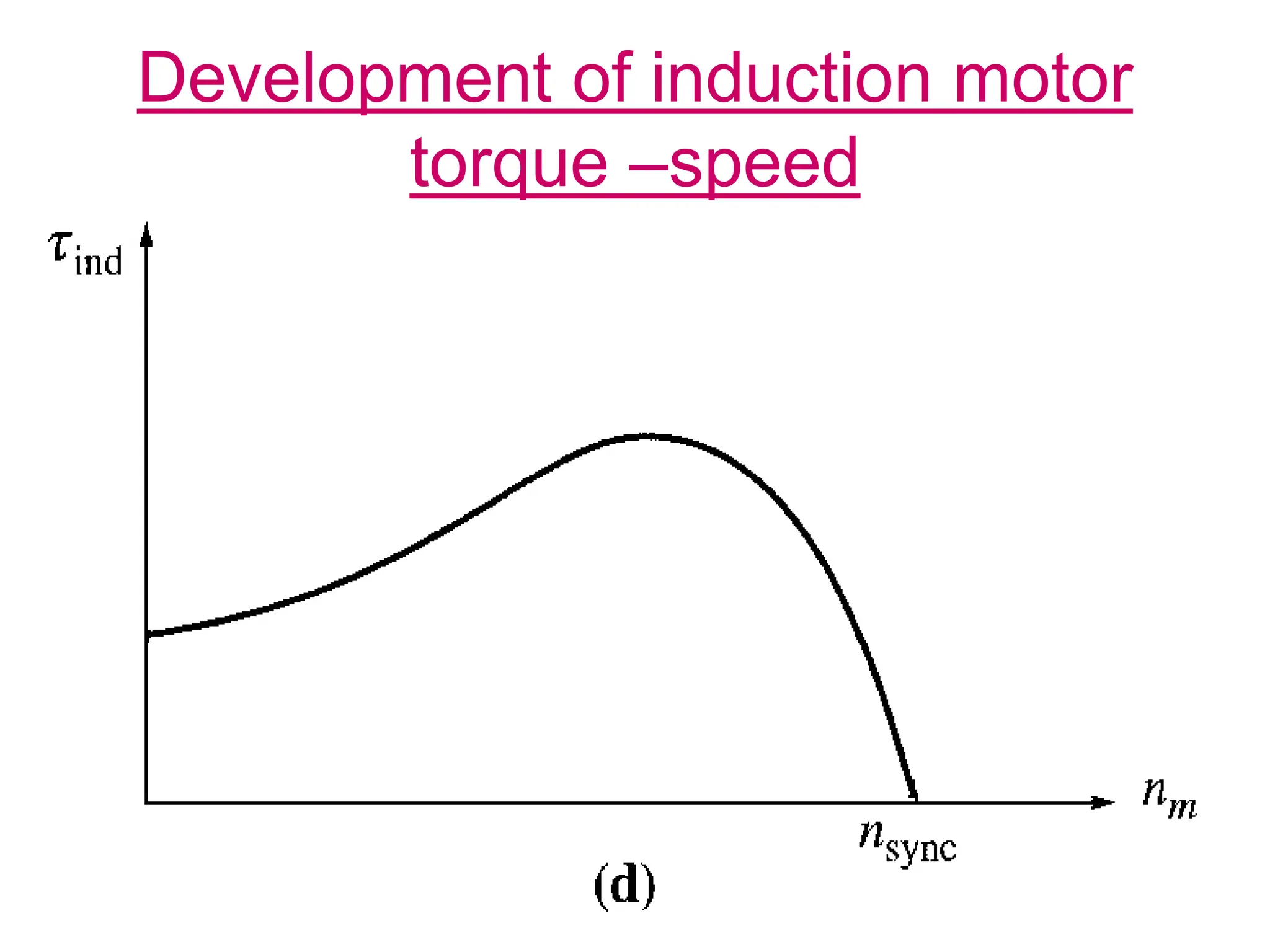
The document describes the torque-speed characteristic of induction motors. It explains that as the load on the motor increases, the slip increases, causing the rotor speed to decrease. This higher slip produces a stronger rotor voltage and current, increasing the rotor magnetic field BR. While BR increases torque, the increased angle δ between BR and the stator field Bnet acts to decrease torque. However, the increase in BR dominates, causing the overall induced torque to rise with increasing load and slip. The document derives an equation for induced torque as a function of slip to represent the torque-speed characteristic of induction motors.
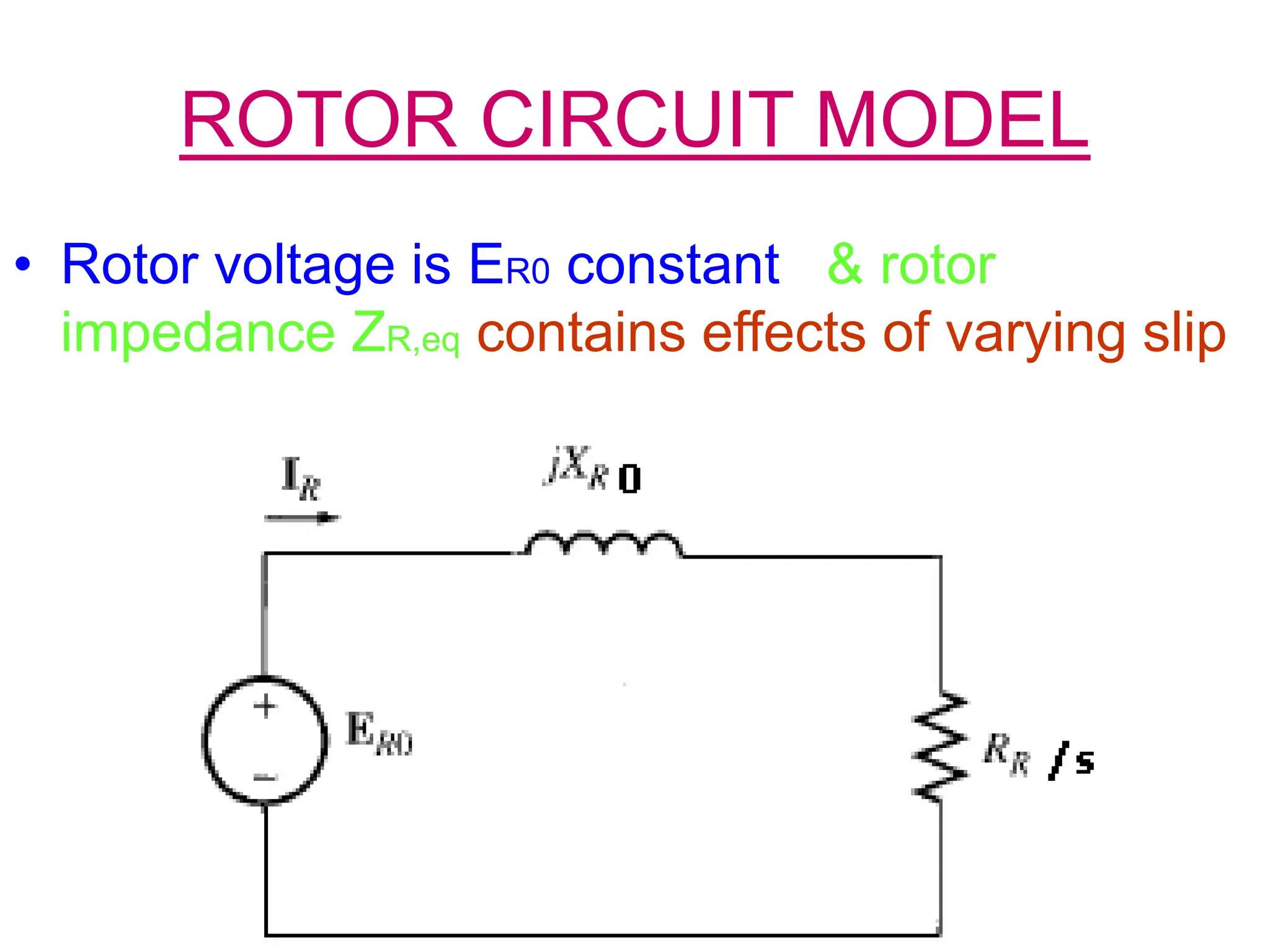
![ROTOR CIRCUIT MODEL
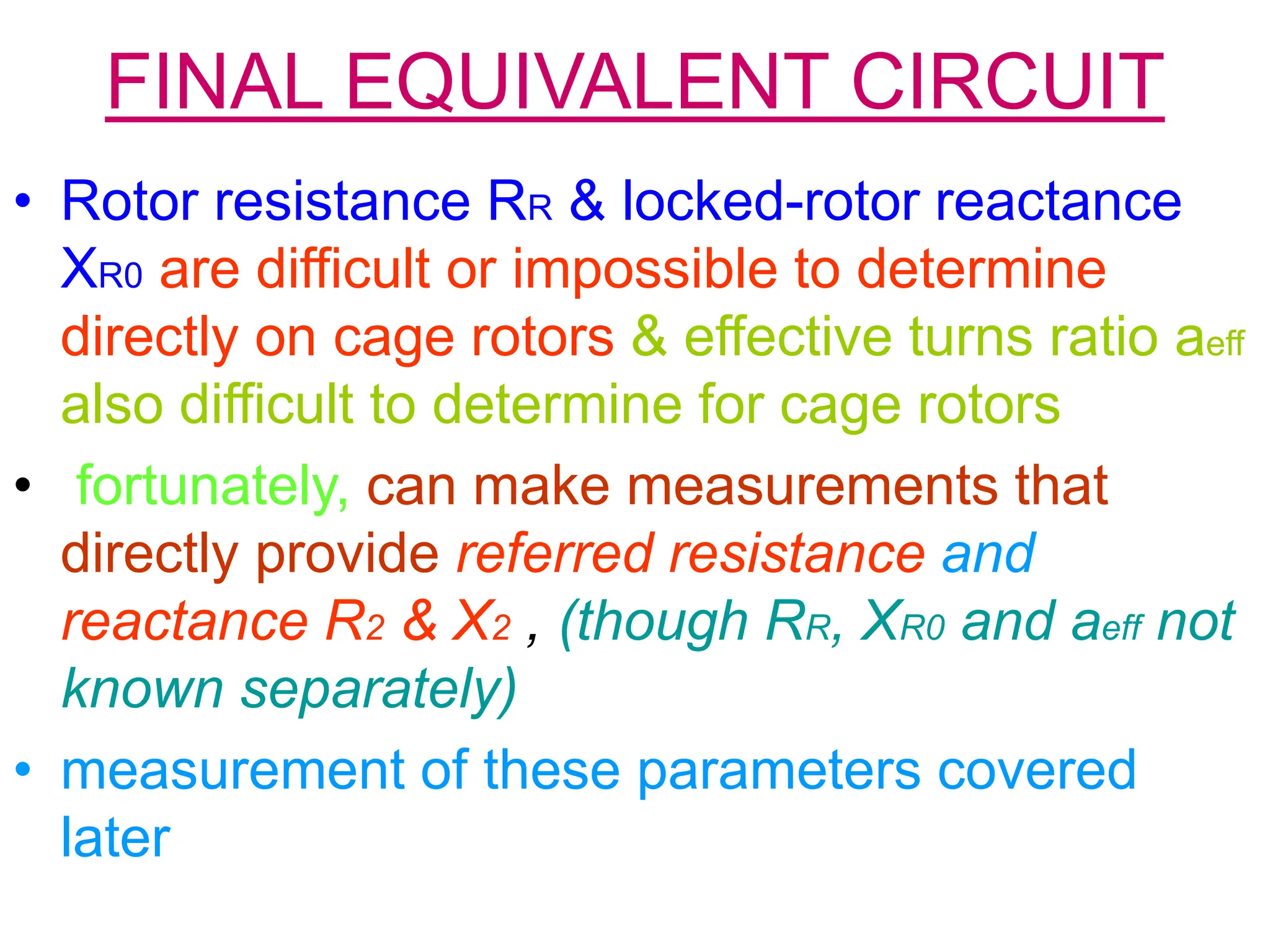
• The rotor current :
IR = ER/ [RR+jXR] (1)
• IR=ER/ [RR+js XR0] or IR=ER0 / [RR /s +j XR0] (2)
• Note: from last equation, can treat rotor effects due to
varying rotor speed as caused by a varying
impedance supplied from a constant voltage source
ER0
• Equivalent rotor impedance from this point of view:
ZR, eq = RR / s + jXR0 (3)
rotor equivalent circuit using this convention shown
next ](https://image.slidesharecdn.com/energyconversion16-240205124500-0d19b2be/75/Induction-motor-rotor-circuit-model-and-energy-conservation-1-2048.jpg)


![POWER & TORQUE IN INDUCTION
MOTORS
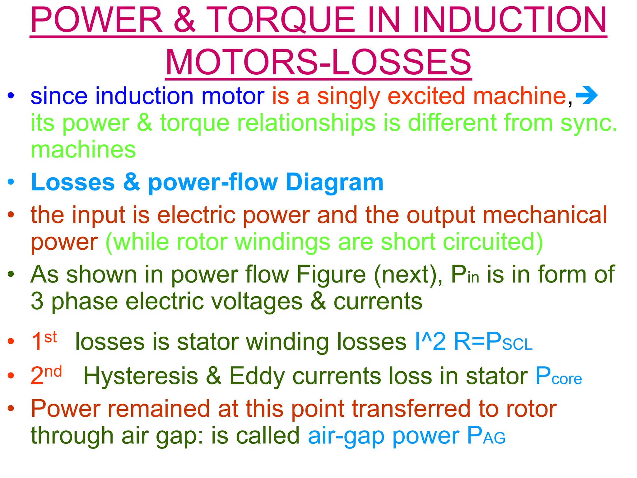
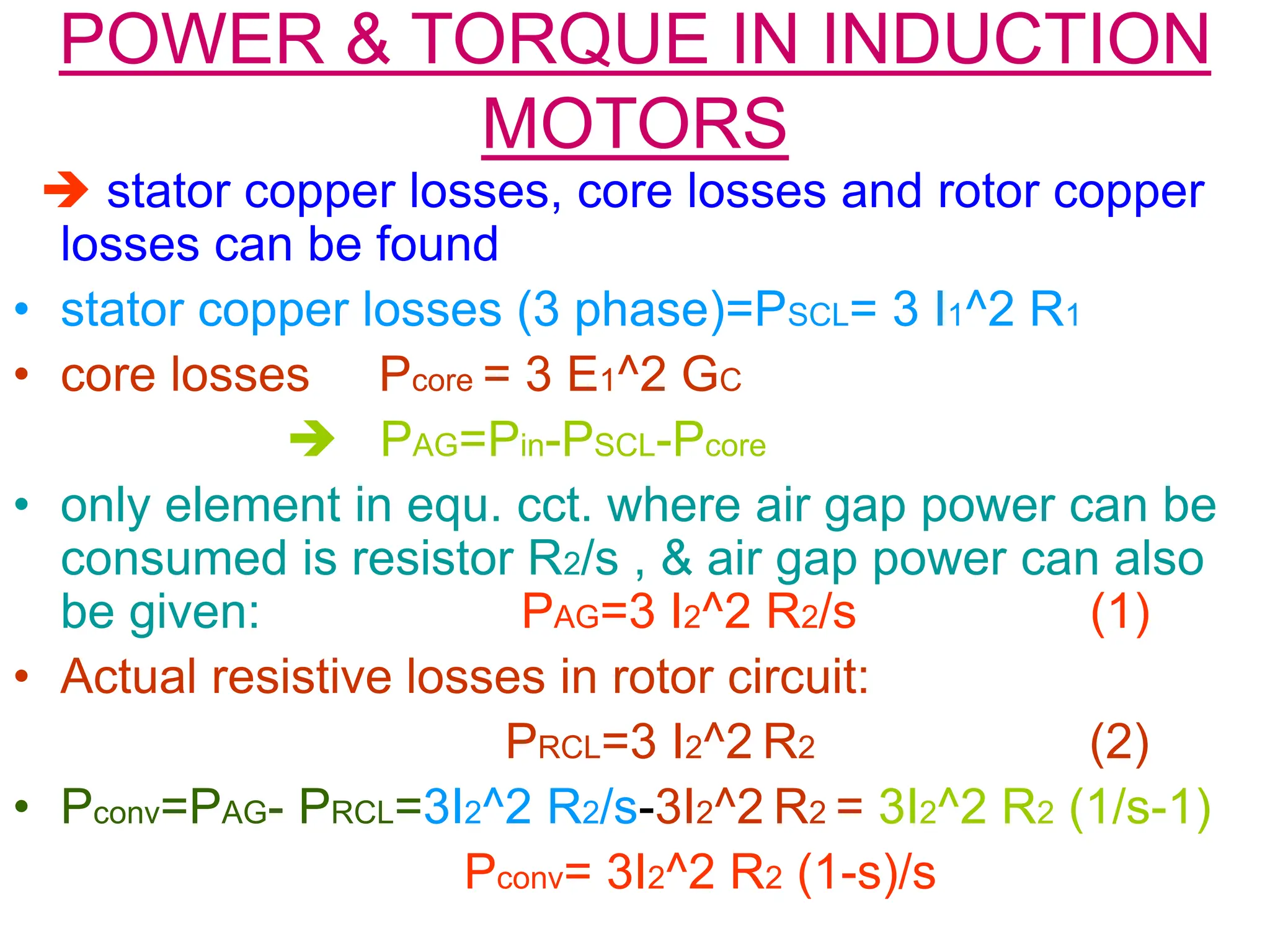
• Employing the equivalent circuit, power &
torque equations can be derived
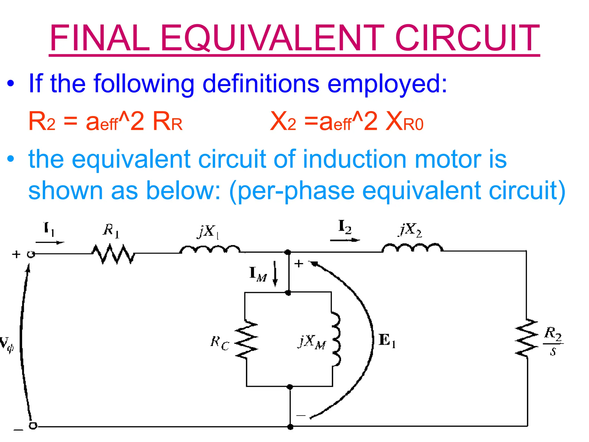
• Input current I1= Vφ/ Zeq =
R1 + jX1 + 1/{[GC-jBM +1/[R2/s +jX2]}](https://image.slidesharecdn.com/energyconversion16-240205124500-0d19b2be/75/Induction-motor-rotor-circuit-model-and-energy-conservation-13-2048.jpg)
![POWER & TORQUE IN INDUCTION
MOTORS
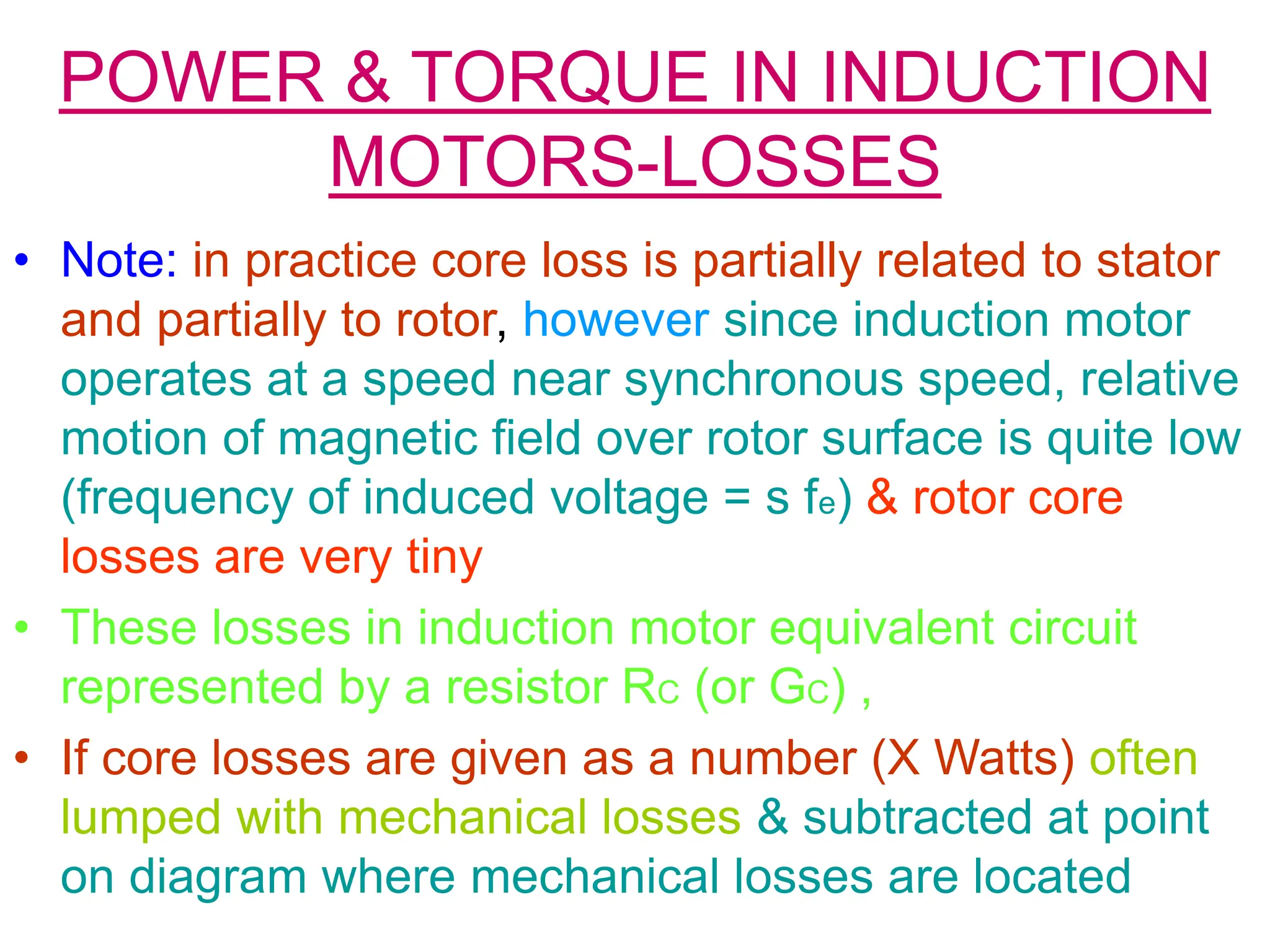
• Induced torque Tind as : torque generated by internal
electric to mechanical power conversion
• It differs from available torque by amount equal to
friction & windage torques in machine
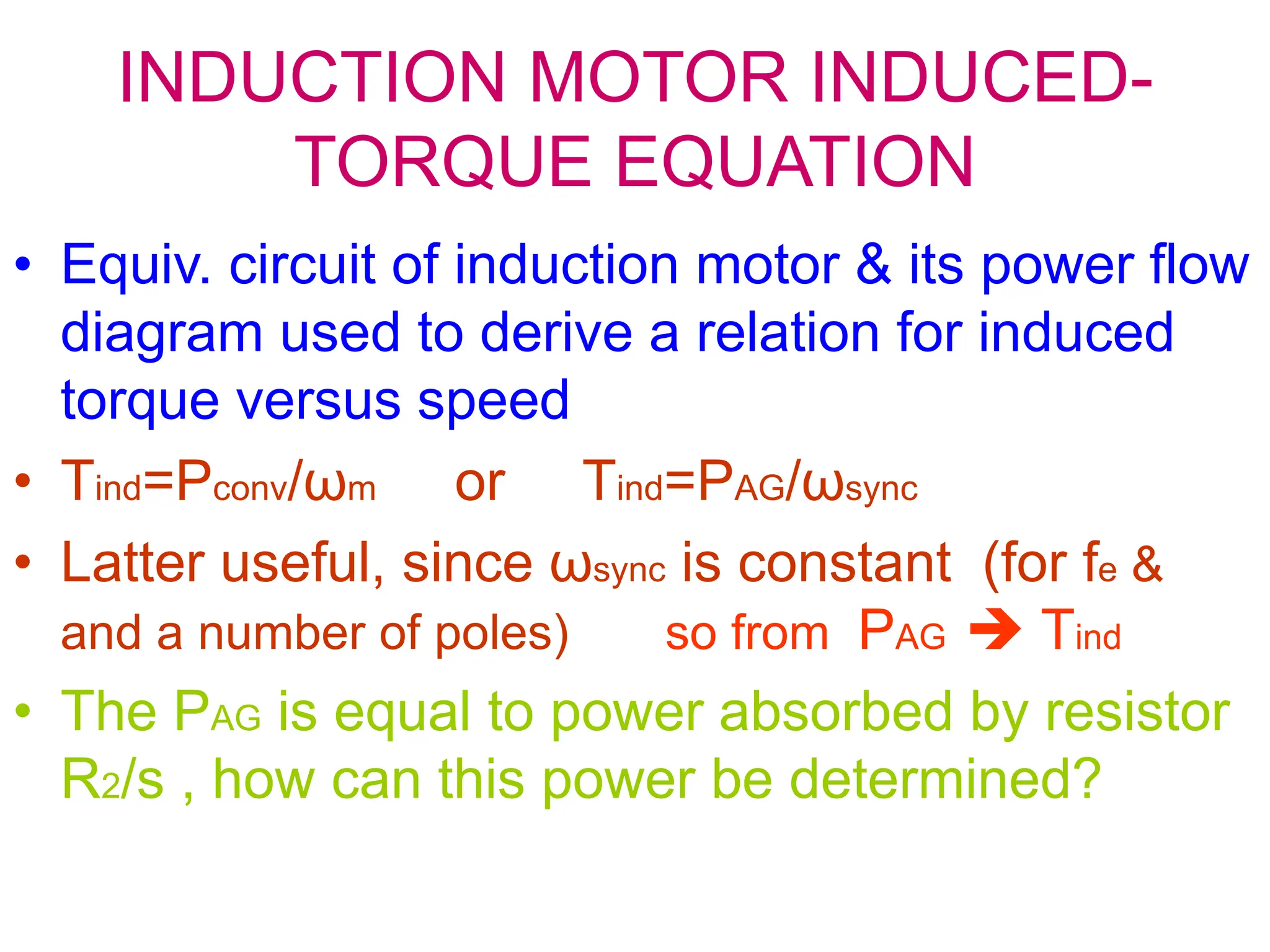
• Tind=Pconv/ωm also called developed torque of machine
• Substituting for Pconv from (3) & for ωm, (1-s) ωsync
Tind= (1-s)PAG/ [(1-s)ωsync]= PAG/ωsync (4)
So (4) express induced torque in terms of air-gap
power & sync. Speed which is constant
PAG yields Tind](https://image.slidesharecdn.com/energyconversion16-240205124500-0d19b2be/75/Induction-motor-rotor-circuit-model-and-energy-conservation-16-2048.jpg)
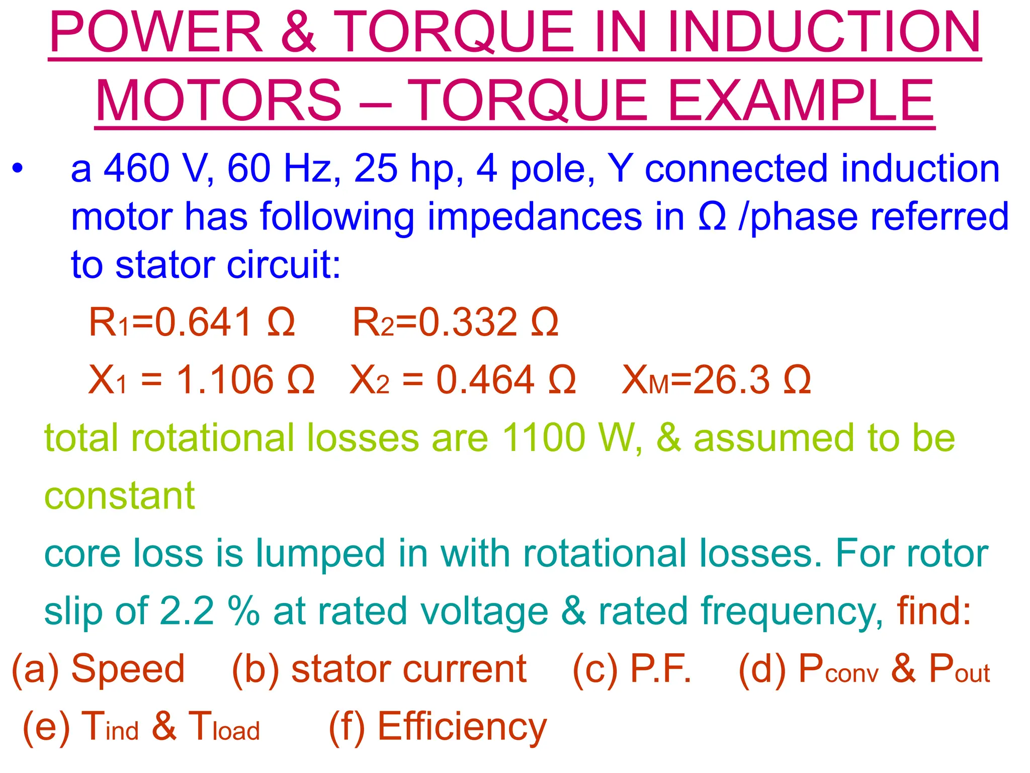
![POWER & TORQUE IN INDUCTION
MOTORS – TORQUE EXAMPLE
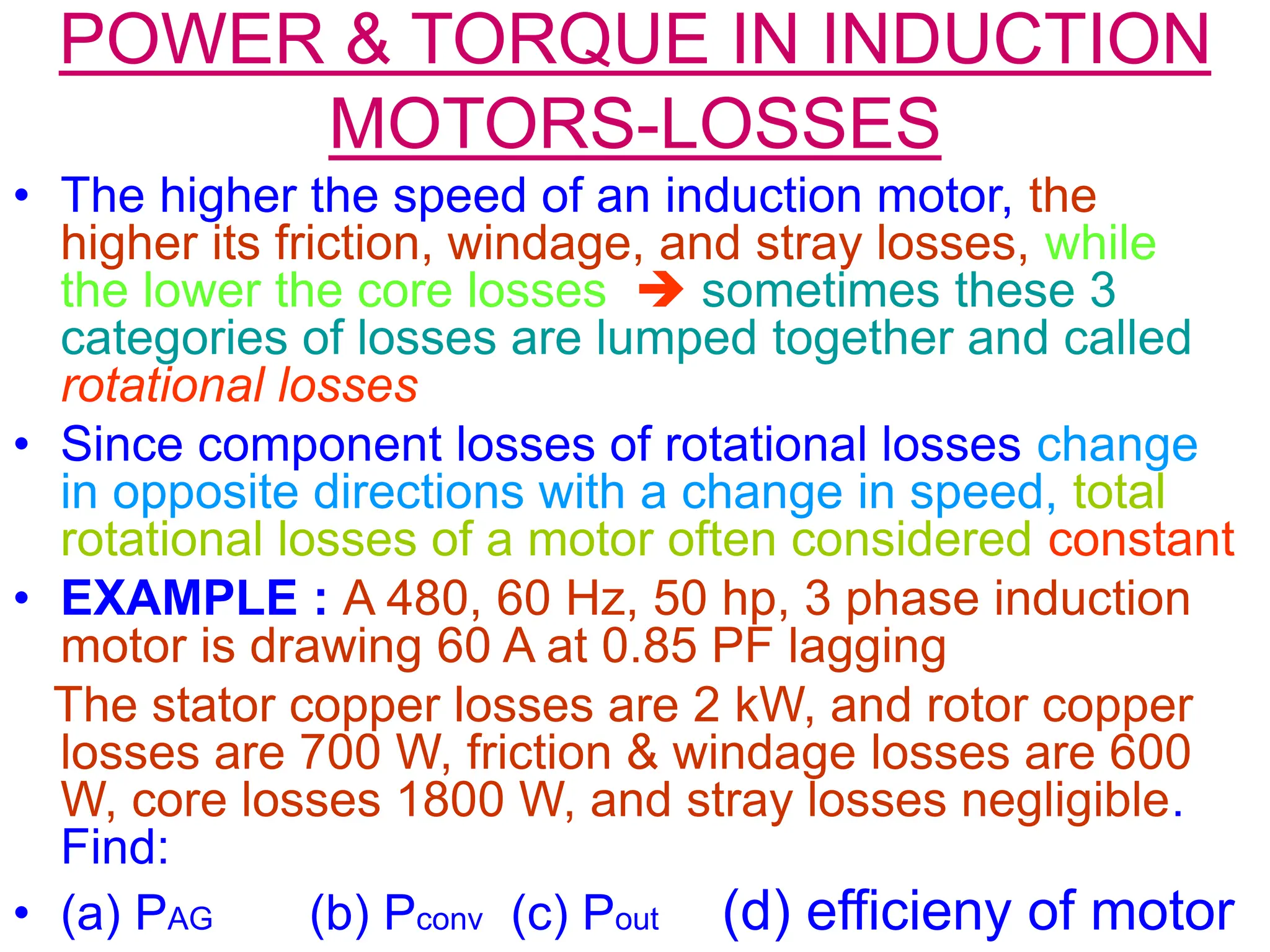
• (a) nsync=120 fe/p=120 x60/4=1800 r/min
ωsync=1800 x 2π x 1/60= 188.5 rad/s
rotor’s mechanical shaft speed:
nm=(1-s) nsync=(1-0.022) x 1800=1760 r/min
ωm= (1-s) ωsync= (1-0.022) x 188.5= 184.4 rad/s
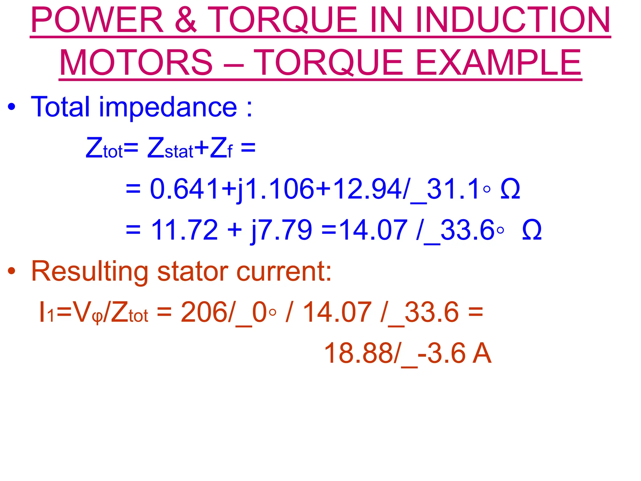
• (b) to find stator current, consider eq. impedance of cct. Then
combine referred rotor impedance in parallel with magnetization
branch, and add stator impedance to the combination in series
• The referred rotor impedance is :
Z2= R2/s + j X2 =0.332 / 0.022 + j0.464
=15.09+j0.464=15.1/_ 1.76◦ Ω
combined magnetization plus rotor impedance is:
Zf = 1/[1/(jXM) + 1/Z2] = 1/ [-j0.038 + 0.0662/_ -1.76◦]=
1/[0.0773/_ -31.1◦]=12.94/_31.1 ◦](https://image.slidesharecdn.com/energyconversion16-240205124500-0d19b2be/75/Induction-motor-rotor-circuit-model-and-energy-conservation-20-2048.jpg)


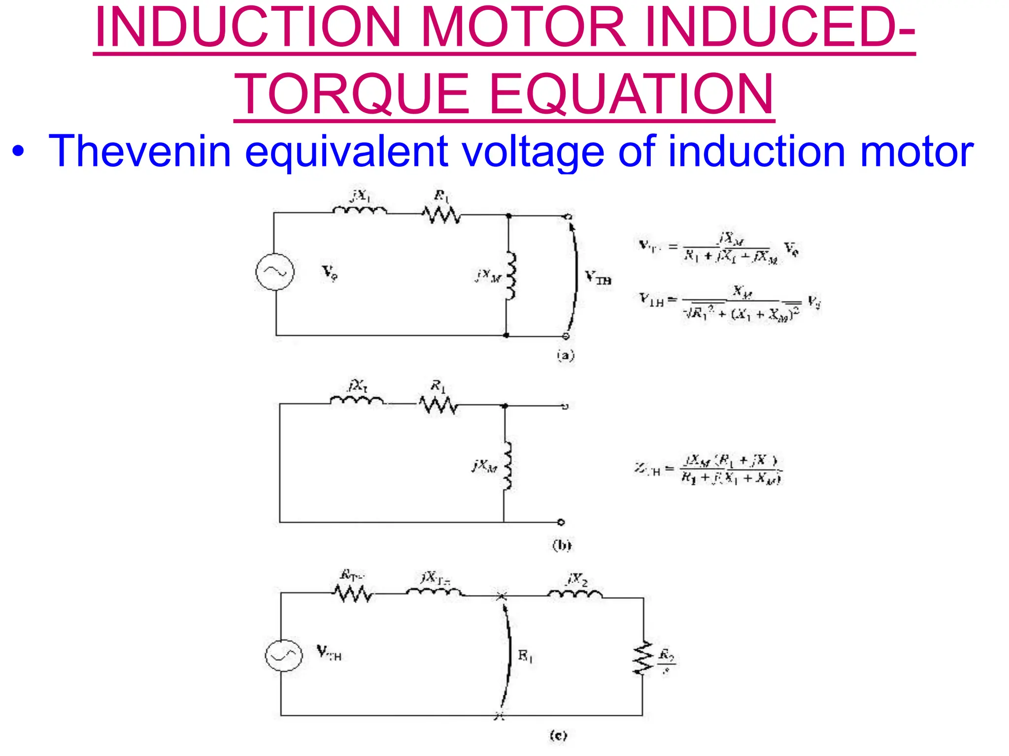
![INDUCTION MOTOR INDUCED-
TORQUE EQUATION
• If I2 can be determined, air-gap power &
induced torque are known
• easiest way to determine Thevenin equivalent
of the portion of circuit to left of arrow E1 in eq.
cct. figure
VTH= Vφ ZM/ [ZM+Z1] = Vφ j XM / [R1+jX1+jXM]
• Magnitude of thevenin voltage:
VTH= Vφ XM / √[R1^2+(X1+XM)^2]
VTH≈ Vφ XM / [X1+XM] , ZTH = Z1ZM /[Z1+ZM]
ZTH=RTH+jXTH = jXM(R1+jX1)/[R1+j(X1+XM)]](https://image.slidesharecdn.com/energyconversion16-240205124500-0d19b2be/75/Induction-motor-rotor-circuit-model-and-energy-conservation-41-2048.jpg)