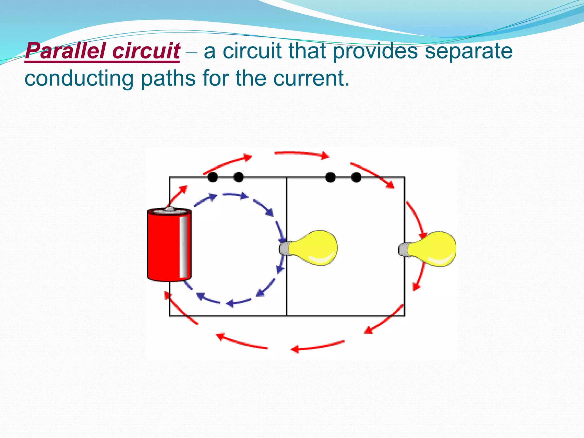
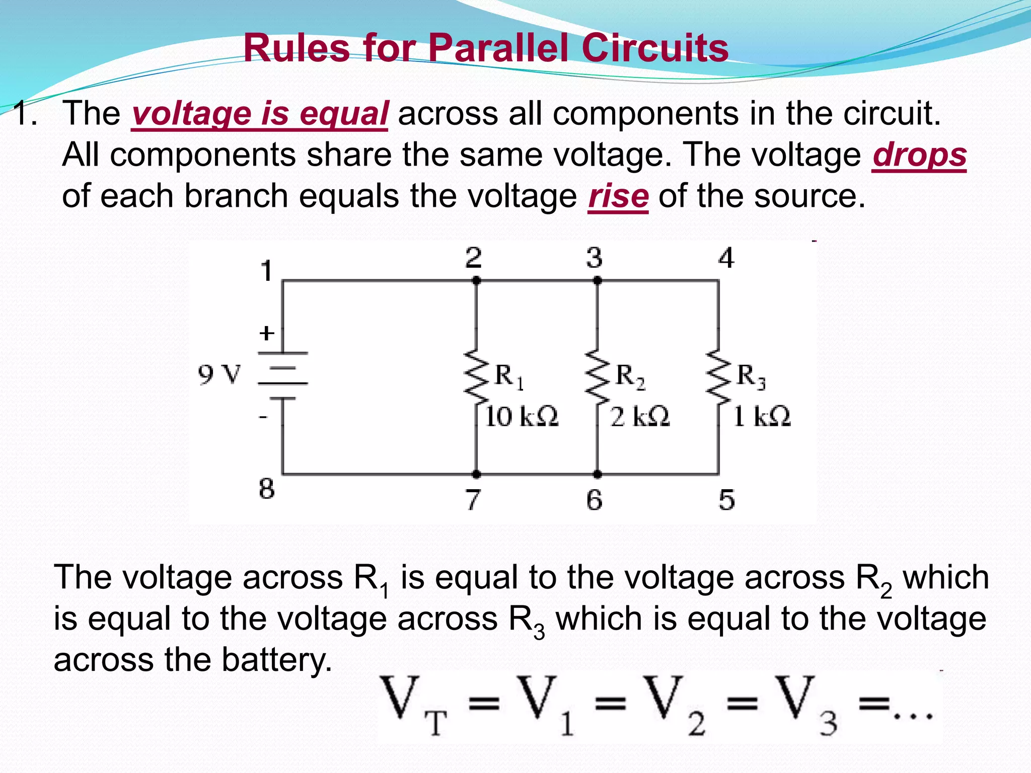
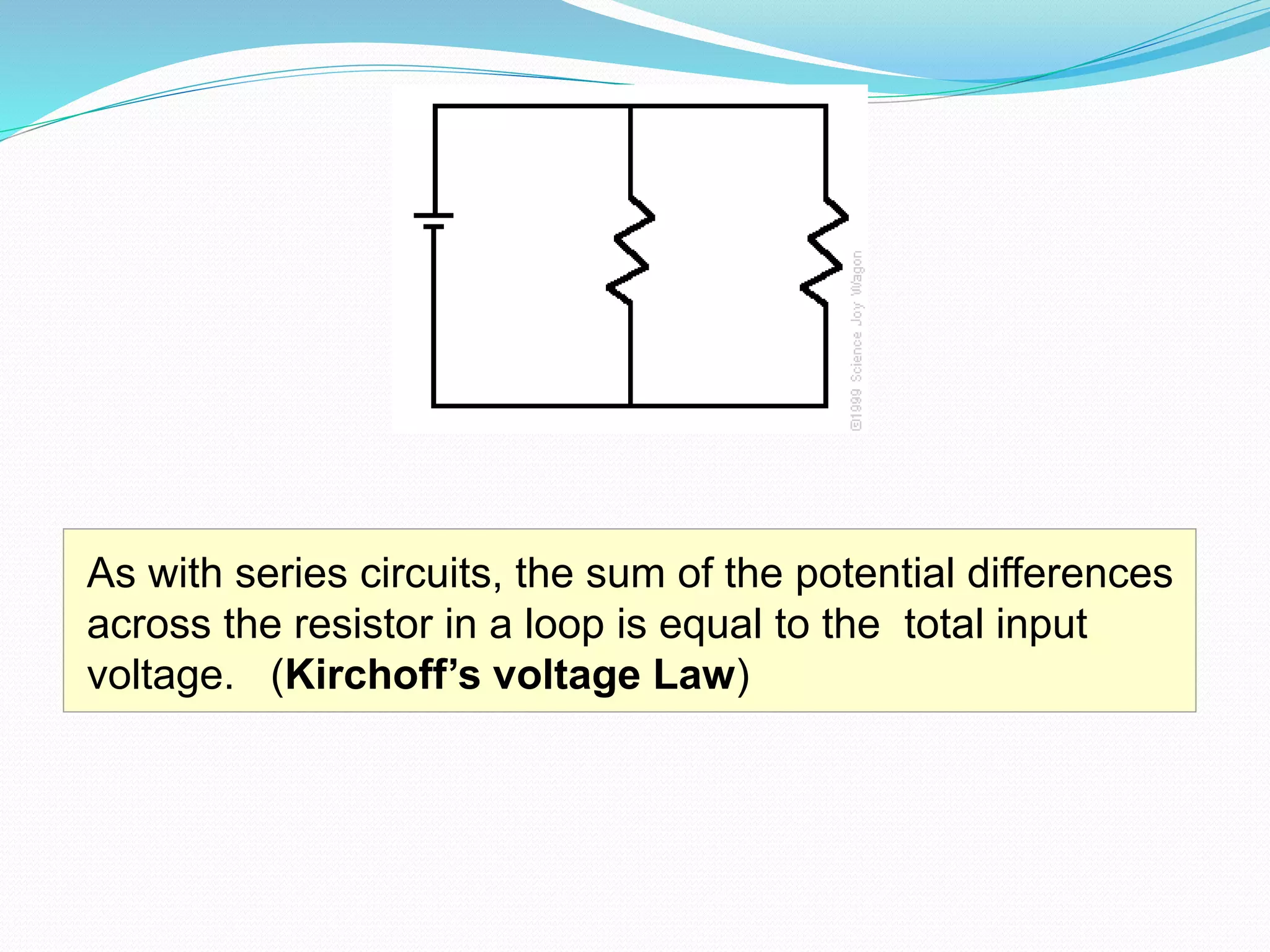
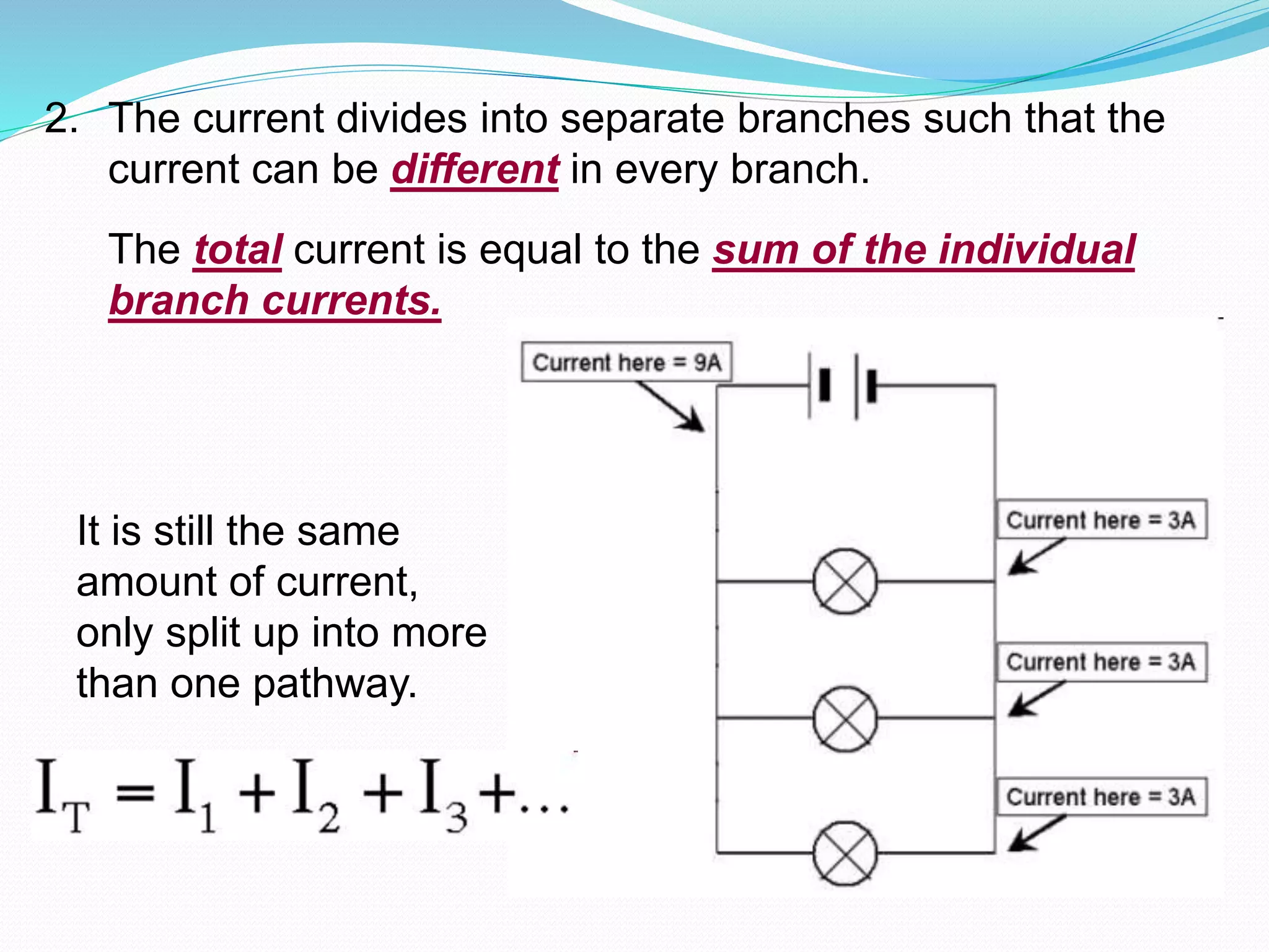
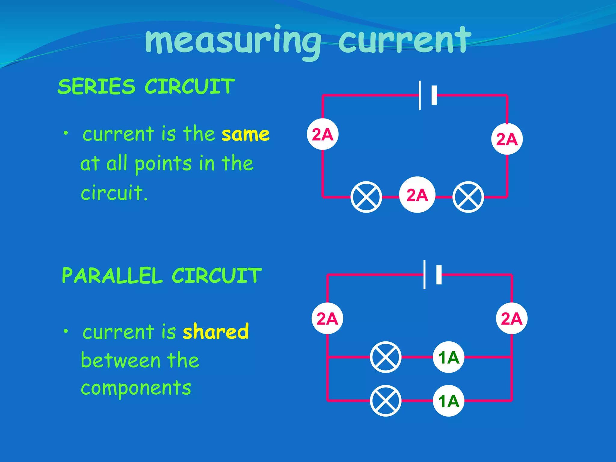
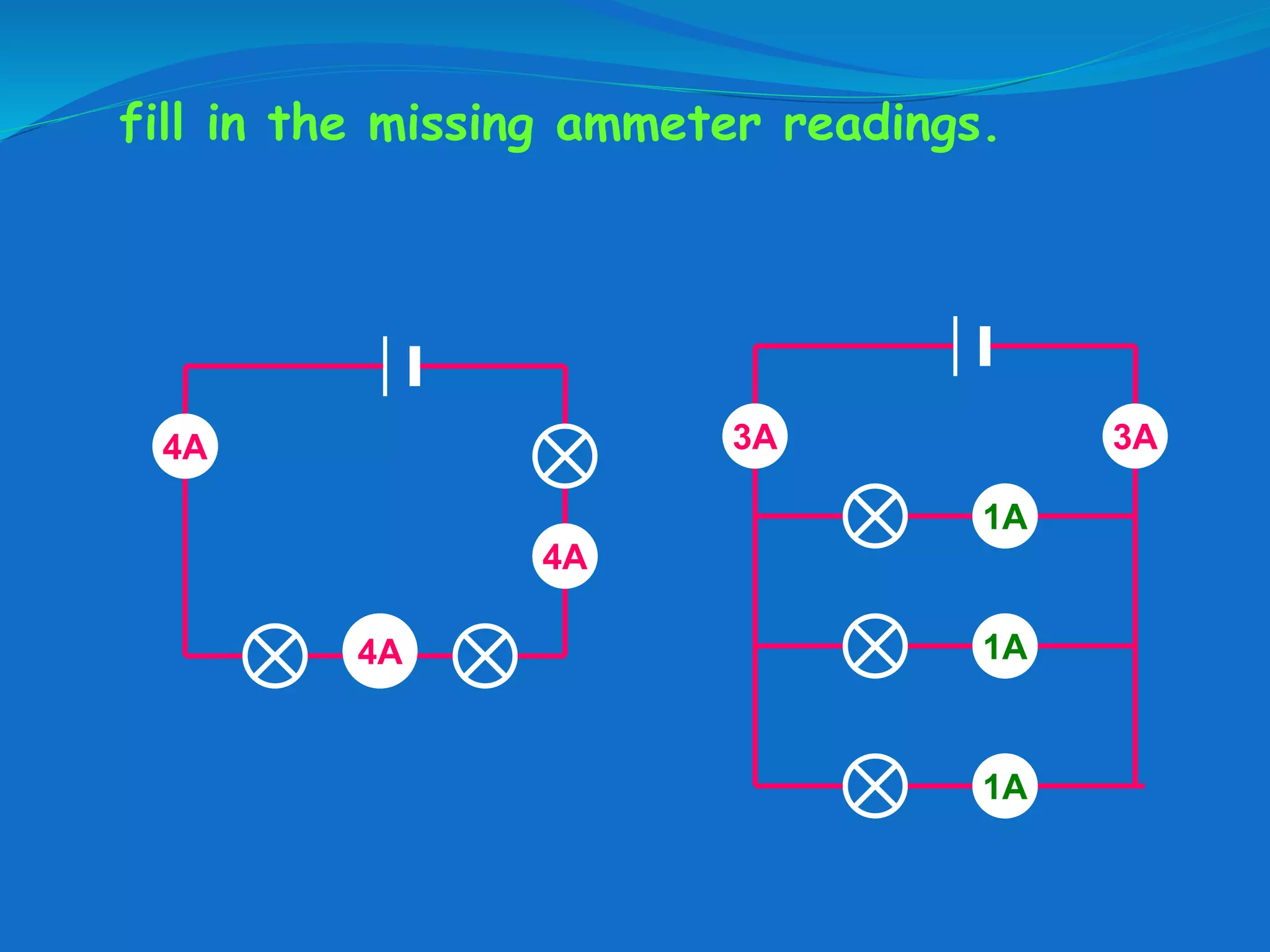
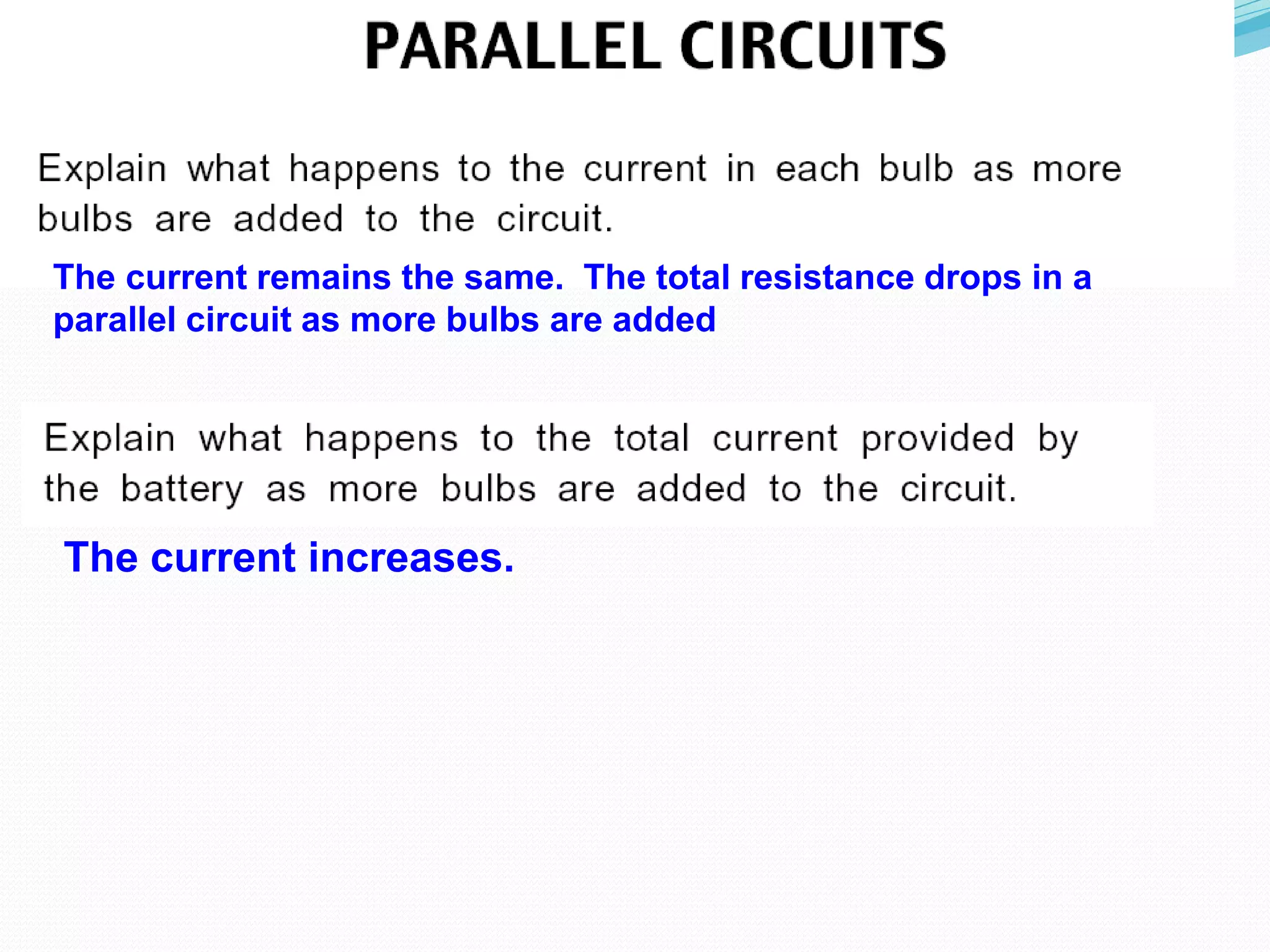
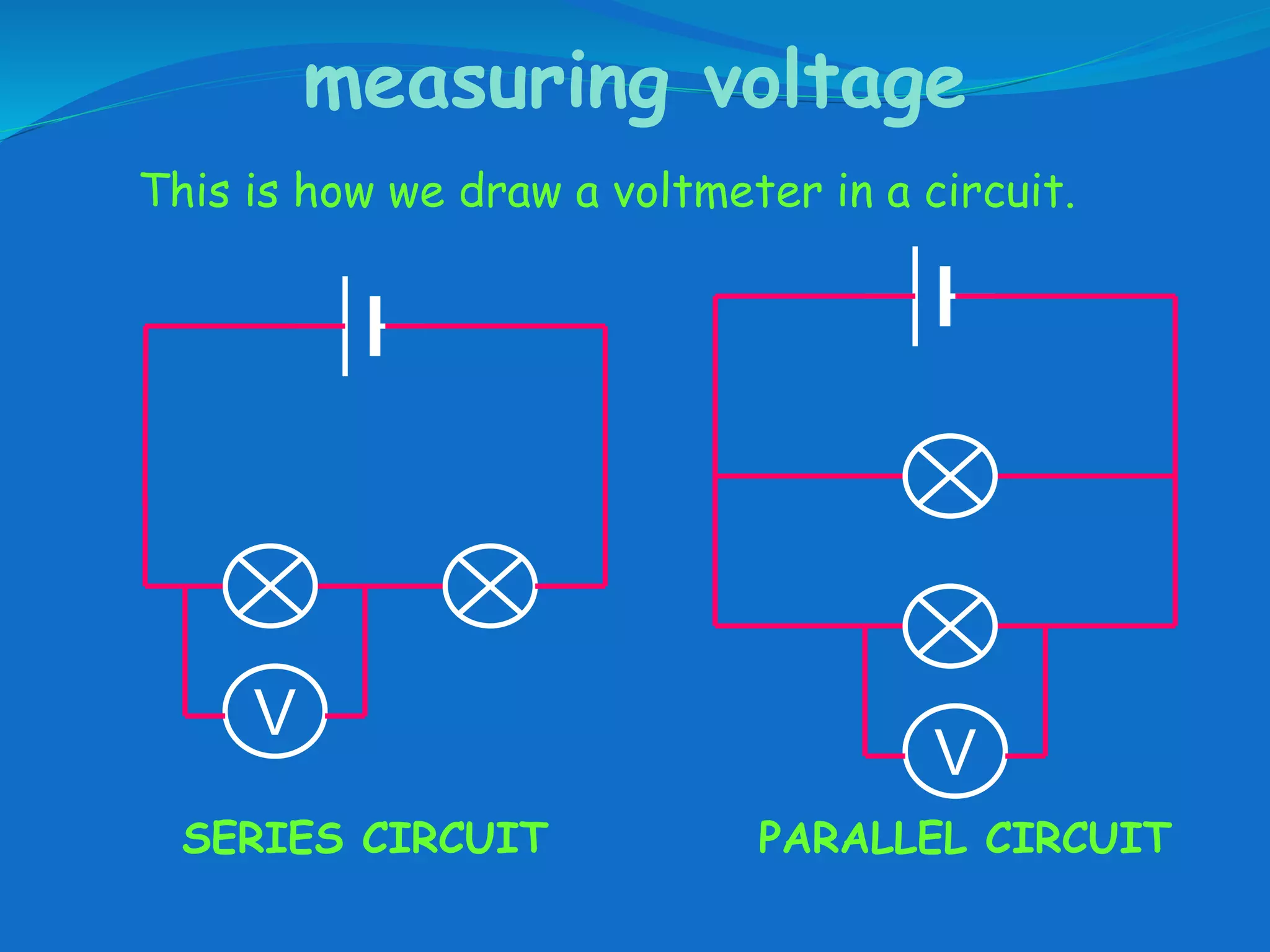
Circuits
- Electrical components connected in different
loops of the same circuit are connected in parallel.
3 light bulbs connected to
a battery in a parallel circuit.
The same parallel circuit
as a circuit diagram.
Twice as many cars can travel on a double road, three times as
many on a three-lane road and so on.
One could say that these two roads are parallel to each other in
that there is more than one path for the cars to follow.
This analogy can be applied to parallel circuits.
Parallel circuit – a circuit that provides separate
conducting paths for the current.
More current flows through the smaller resistance. More
charges take the easiest path.
Rules for Parallel Circuits
1. The voltage is equal across all components in the circuit.
All components share the same voltage. The voltage drops
of each branch equals the voltage rise of the source.
The voltage across R1 is equal to the voltage across R2 which
is equal to the voltage across R3 which is equal to the voltage
across the battery.
As with series circuits, the sum of the potential differences
across the resistor in a loop is equal to the total input
voltage. (Kirchoff’s voltage Law)
2. The current divides into separate branches such that the
current can be different in every branch.
The total current is equal to the sum of the individual
branch currents.
It is still the same
amount of current,
only split up into more
than one pathway.
In a parallel circuit, the point where the current a
separates is called a junction.
Kirchhoff's Current Law
The sum of the currents entering a junction is
equal to the sum of the currents leaving the
junction.
In this example you will notice 8 Amps and 1 Amp entering
the junction while 7 Amps and 2 Amps leave. This makes a
total of 9 Amps entering and 9 Amps leaving.
A B
The current going into
The junction equals
7 amps (1A + 2A + 4A).
The current leaving the
Junction is 7 amps (7A)
The current entering the
junction is 6 amps ( 5A + 1A).
The current leaving the
Junction is 6 amps (4A + 2A)
The diagram above represents current flowing in
branches of an electric circuit. What is the current
at point B? 13 A
3. When resistors are connected in parallel, the
total resistance of the circuit decreases.
The more branches you add to a parallel circuit, the lower
the total resistance becomes.
4. The total resistance of a parallel circuit is always
less than the value of the smallest resistor.
Formula for Total Parallel Resistance
The inverse of the total resistance of the circuit (also called
effective or equivalent resistance) is equal to the sum of the
inverses of the individual resistances.
For 2 resistors,
RT = R1 x R2
R1 + R2
which means…
Power In Parallel Circuits
Total power in a parallel circuit is found by adding up
the powers of all the individual resistors, the same
as for series circuits.
Connecting lights and appliances in parallel makes them operate
independently. If one goes off, the other can still operate.
measuring current
SERIES CIRCUIT
PARALLEL CIRCUIT
• current is the same
at all points in the
circuit.
2A 2A
2A
• current is shared
between the
components
2A2A
1A
1A
fill in the missing ammeter readings.
?
?
4A
4A
4A
3A?
?
1A
?
3A
1A
1A
The circuit is no longer complete, therefore current can not flow
The voltage decreases because the current is decreased
and the resistance increases.
The current remains the same. The total resistance drops in a
parallel circuit as more bulbs are added
The current increases.
measuring current
Electric current is measured in amps (A) using
an ammeter connected in series in the circuit.
A
measuring current
A A
This is how we draw an ammeter in a circuit.
SERIES CIRCUIT PARALLEL CIRCUIT
measuring voltage
The ‘electrical push’ which the cell gives to the current
is called the voltage. It is measured in volts (V) on a
voltmeter
V
measuring voltage
V
This is how we draw a voltmeter in a circuit.
SERIES CIRCUIT PARALLEL CIRCUIT
V

4.3.b form 4 parallel circuits

  • 1.
  • 2.
    - Electrical componentsconnected in different loops of the same circuit are connected in parallel.
  • 3.
    3 light bulbsconnected to a battery in a parallel circuit. The same parallel circuit as a circuit diagram.
  • 4.
    Twice as manycars can travel on a double road, three times as many on a three-lane road and so on. One could say that these two roads are parallel to each other in that there is more than one path for the cars to follow. This analogy can be applied to parallel circuits.
  • 5.
    Parallel circuit –a circuit that provides separate conducting paths for the current.
  • 6.
    More current flowsthrough the smaller resistance. More charges take the easiest path.
  • 7.
    Rules for ParallelCircuits 1. The voltage is equal across all components in the circuit. All components share the same voltage. The voltage drops of each branch equals the voltage rise of the source. The voltage across R1 is equal to the voltage across R2 which is equal to the voltage across R3 which is equal to the voltage across the battery.
  • 8.
    As with seriescircuits, the sum of the potential differences across the resistor in a loop is equal to the total input voltage. (Kirchoff’s voltage Law)
  • 9.
    2. The currentdivides into separate branches such that the current can be different in every branch. The total current is equal to the sum of the individual branch currents. It is still the same amount of current, only split up into more than one pathway.
  • 10.
    In a parallelcircuit, the point where the current a separates is called a junction.
  • 11.
    Kirchhoff's Current Law Thesum of the currents entering a junction is equal to the sum of the currents leaving the junction. In this example you will notice 8 Amps and 1 Amp entering the junction while 7 Amps and 2 Amps leave. This makes a total of 9 Amps entering and 9 Amps leaving.
  • 12.
    A B The currentgoing into The junction equals 7 amps (1A + 2A + 4A). The current leaving the Junction is 7 amps (7A) The current entering the junction is 6 amps ( 5A + 1A). The current leaving the Junction is 6 amps (4A + 2A)
  • 13.
    The diagram aboverepresents current flowing in branches of an electric circuit. What is the current at point B? 13 A
  • 14.
    3. When resistorsare connected in parallel, the total resistance of the circuit decreases. The more branches you add to a parallel circuit, the lower the total resistance becomes. 4. The total resistance of a parallel circuit is always less than the value of the smallest resistor.
  • 17.
    Formula for TotalParallel Resistance The inverse of the total resistance of the circuit (also called effective or equivalent resistance) is equal to the sum of the inverses of the individual resistances. For 2 resistors, RT = R1 x R2 R1 + R2 which means…
  • 18.
    Power In ParallelCircuits Total power in a parallel circuit is found by adding up the powers of all the individual resistors, the same as for series circuits.
  • 19.
    Connecting lights andappliances in parallel makes them operate independently. If one goes off, the other can still operate.
  • 20.
    measuring current SERIES CIRCUIT PARALLELCIRCUIT • current is the same at all points in the circuit. 2A 2A 2A • current is shared between the components 2A2A 1A 1A
  • 21.
    fill in themissing ammeter readings. ? ? 4A 4A 4A 3A? ? 1A ? 3A 1A 1A
  • 22.
    The circuit isno longer complete, therefore current can not flow The voltage decreases because the current is decreased and the resistance increases.
  • 23.
    The current remainsthe same. The total resistance drops in a parallel circuit as more bulbs are added The current increases.
  • 24.
    measuring current Electric currentis measured in amps (A) using an ammeter connected in series in the circuit. A
  • 25.
    measuring current A A Thisis how we draw an ammeter in a circuit. SERIES CIRCUIT PARALLEL CIRCUIT
  • 26.
    measuring voltage The ‘electricalpush’ which the cell gives to the current is called the voltage. It is measured in volts (V) on a voltmeter V
  • 27.
    measuring voltage V This ishow we draw a voltmeter in a circuit. SERIES CIRCUIT PARALLEL CIRCUIT V