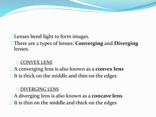
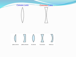
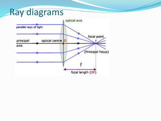
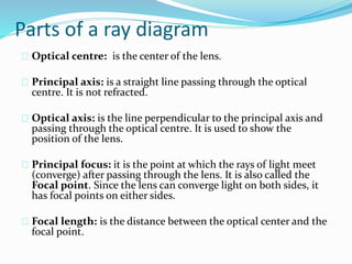
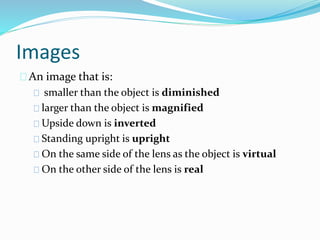
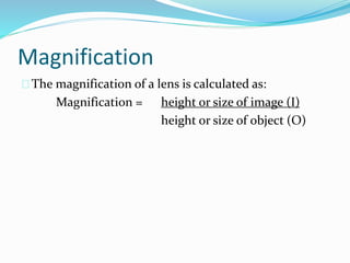
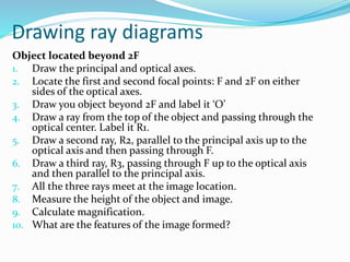
Lenses
Lenses bend light to form images.
There are 2 types of lenses: Converging and Diverging
lenses.
CONVEX LENS
A converging lens is also known as a convex lens
It is thick on the middle and thin on the edges
DIVERGING LENS
A diverging lens is also known as a concave lens
It is thin on the middle and thick on the edges
Ray diagrams
Parts of a ray diagram
Optical centre: is the center of the lens.
Principal axis: is a straight line passing through the optical
centre. It is not refracted.
Optical axis: is the line perpendicular to the principal axis and
passing through the optical centre. It is used to show the
position of the lens.
Principal focus: it is the point at which the rays of light meet
(converge) after passing through the lens. It is also called the
Focal point. Since the lens can converge light on both sides, it
has focal points on either sides.
Focal length: is the distance between the optical center and the
focal point.
Images
An image that is:
smaller than the object is diminished
larger than the object is magnified
Upside down is inverted
Standing upright is upright
On the same side of the lens as the object is virtual
On the other side of the lens is real
Magnification
The magnification of a lens is calculated as:
Magnification = height or size of image (I)
height or size of object (O)
Exercise
Use a hand lens to draw an image of the given
spacemen. Calculate the magnification.
Drawing ray diagrams
Object located beyond 2F
1. Draw the principal and optical axes.
2. Locate the first and second focal points: F and 2F on either
sides of the optical axes.
3. Draw you object beyond 2F and label it ‘O’
4. Draw a ray from the top of the object and passing through the
optical center. Label it R1.
5. Draw a second ray, R2, parallel to the principal axis up to the
optical axis and then passing through F.
6. Draw a third ray, R3, passing through F up to the optical axis
and then parallel to the principal axis.
7. All the three rays meet at the image location.
8. Measure the height of the object and image.
9. Calculate magnification.
10. What are the features of the image formed?
Prep work
Draw ray diagrams for the object located on the
following positions;
1. At 2F
2. Between 2F and F
3. At F
4. Between F and optical centre.
State the properties of the images formed and calculate
magnification.
Thank you!

3.3 form 4 converging lens

  • 1.
  • 2.
    Lenses bend lightto form images. There are 2 types of lenses: Converging and Diverging lenses. CONVEX LENS A converging lens is also known as a convex lens It is thick on the middle and thin on the edges DIVERGING LENS A diverging lens is also known as a concave lens It is thin on the middle and thick on the edges
  • 4.
  • 5.
    Parts of aray diagram Optical centre: is the center of the lens. Principal axis: is a straight line passing through the optical centre. It is not refracted. Optical axis: is the line perpendicular to the principal axis and passing through the optical centre. It is used to show the position of the lens. Principal focus: it is the point at which the rays of light meet (converge) after passing through the lens. It is also called the Focal point. Since the lens can converge light on both sides, it has focal points on either sides. Focal length: is the distance between the optical center and the focal point.
  • 6.
    Images An image thatis: smaller than the object is diminished larger than the object is magnified Upside down is inverted Standing upright is upright On the same side of the lens as the object is virtual On the other side of the lens is real
  • 7.
    Magnification The magnification ofa lens is calculated as: Magnification = height or size of image (I) height or size of object (O)
  • 8.
    Exercise Use a handlens to draw an image of the given spacemen. Calculate the magnification.
  • 9.
    Drawing ray diagrams Objectlocated beyond 2F 1. Draw the principal and optical axes. 2. Locate the first and second focal points: F and 2F on either sides of the optical axes. 3. Draw you object beyond 2F and label it ‘O’ 4. Draw a ray from the top of the object and passing through the optical center. Label it R1. 5. Draw a second ray, R2, parallel to the principal axis up to the optical axis and then passing through F. 6. Draw a third ray, R3, passing through F up to the optical axis and then parallel to the principal axis. 7. All the three rays meet at the image location. 8. Measure the height of the object and image. 9. Calculate magnification. 10. What are the features of the image formed?
  • 10.
    Prep work Draw raydiagrams for the object located on the following positions; 1. At 2F 2. Between 2F and F 3. At F 4. Between F and optical centre. State the properties of the images formed and calculate magnification.
  • 11.