ELECTRIC CIRCUIT
•A closedloop through which current can flow.
•For a continuous flow of electrons, there must be a
complete circuit with no gaps.
•A gap is usually provided by an electric switch that can
be opened or closed to either cut off or allow energy
to flow.
3.
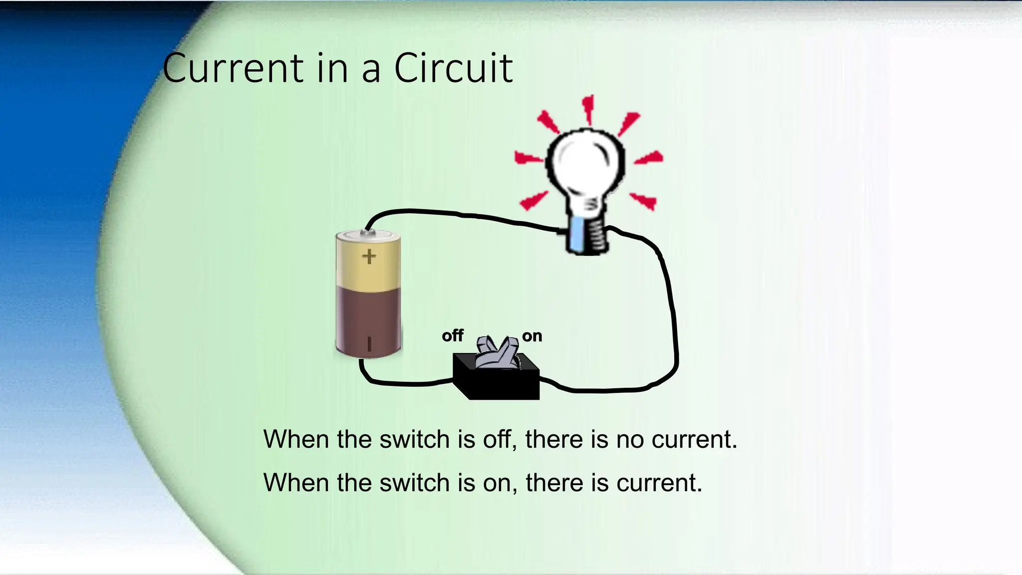
Current in aCircuit
When the switch is off, there is no current.
When the switch is on, there is current.
off on
off on
4.
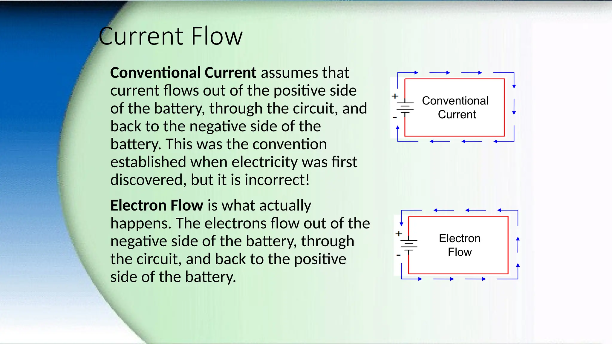
Current Flow
Conventional Currentassumes that
current flows out of the positive side
of the battery, through the circuit, and
back to the negative side of the
battery. This was the convention
established when electricity was first
discovered, but it is incorrect!
Electron Flow is what actually
happens. The electrons flow out of the
negative side of the battery, through
the circuit, and back to the positive
side of the battery.
Electron
Flow
Conventional
Current
5.
Components of ELECTRICCIRCUIT
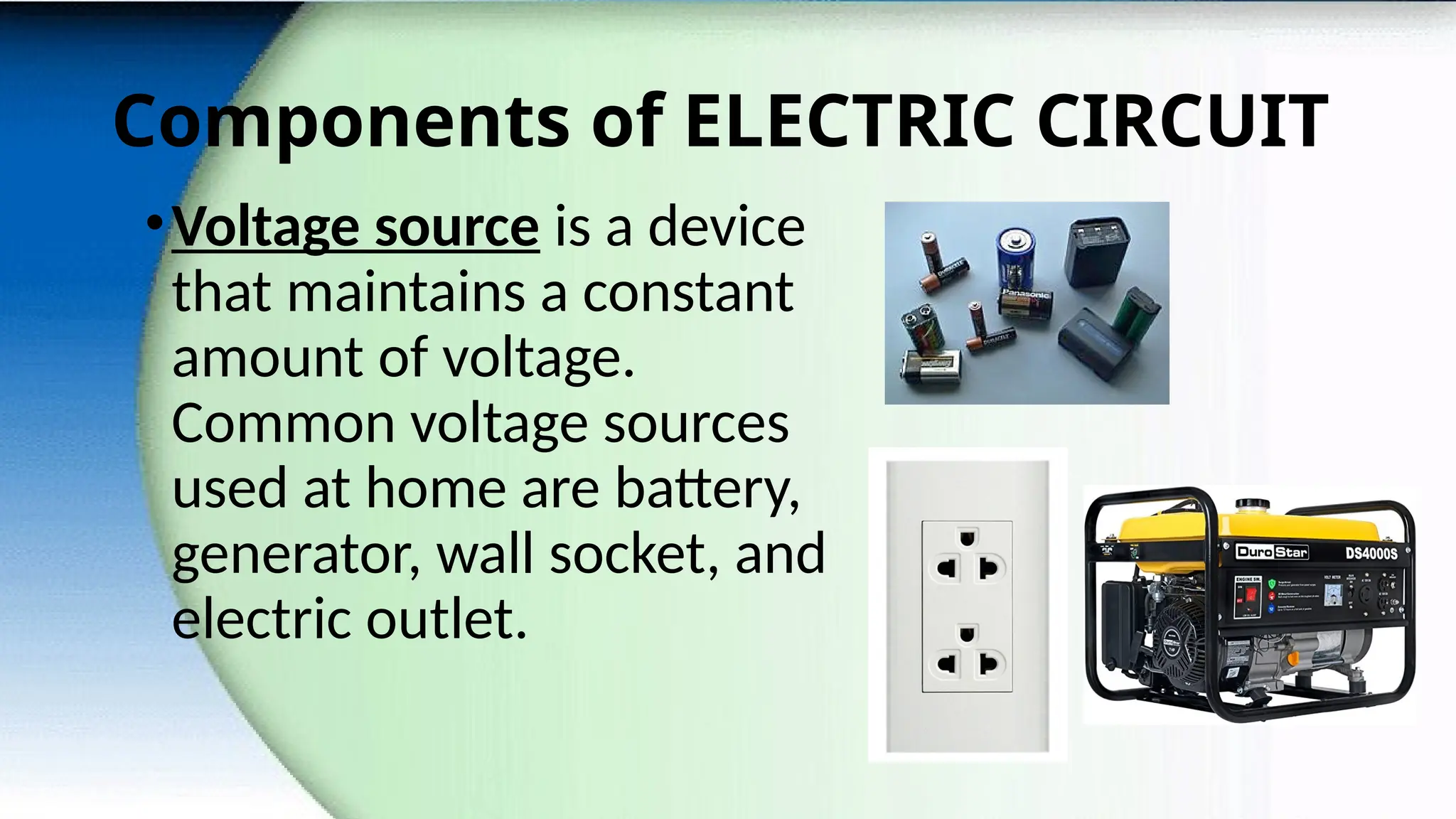
•Voltage source is a device
that maintains a constant
amount of voltage.
Common voltage sources
used at home are battery,
generator, wall socket, and
electric outlet.
6.
Components of ELECTRICCIRCUIT
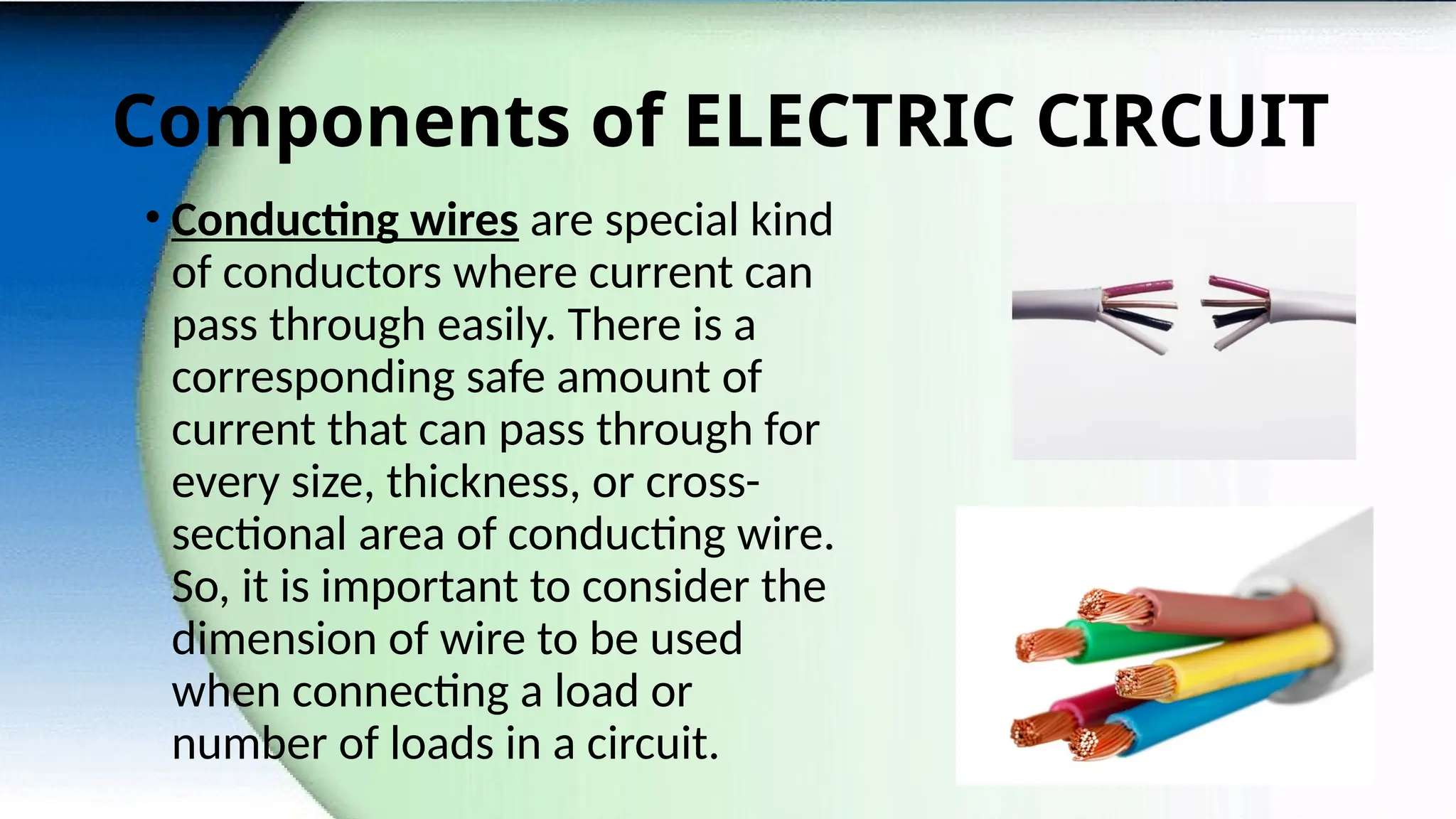
• Conducting wires are special kind
of conductors where current can
pass through easily. There is a
corresponding safe amount of
current that can pass through for
every size, thickness, or cross-
sectional area of conducting wire.
So, it is important to consider the
dimension of wire to be used
when connecting a load or
number of loads in a circuit.
7.
Components of ELECTRICCIRCUIT
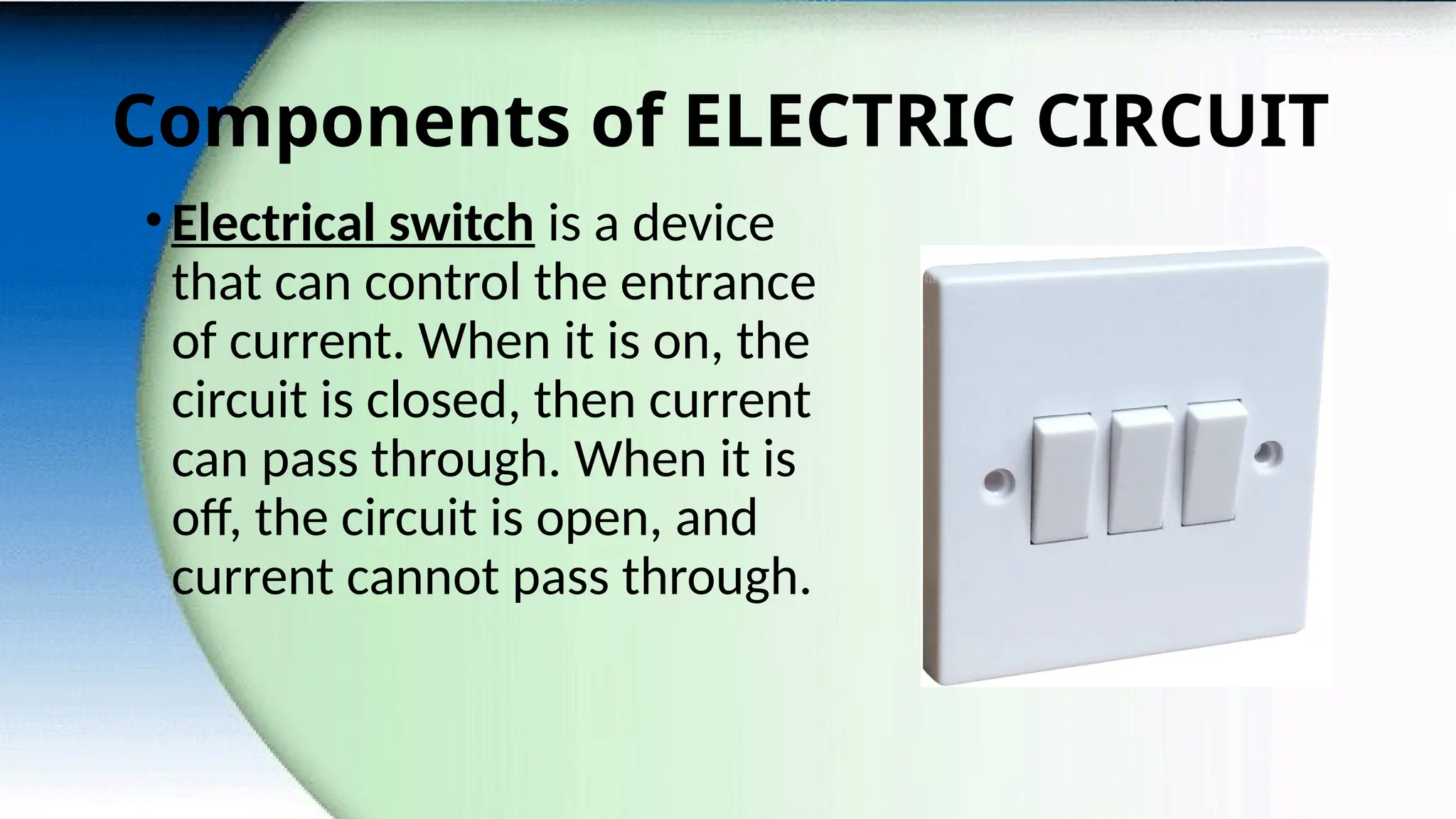
•Electrical switch is a device
that can control the entrance
of current. When it is on, the
circuit is closed, then current
can pass through. When it is
off, the circuit is open, and
current cannot pass through.
8.
Components of ELECTRICCIRCUIT
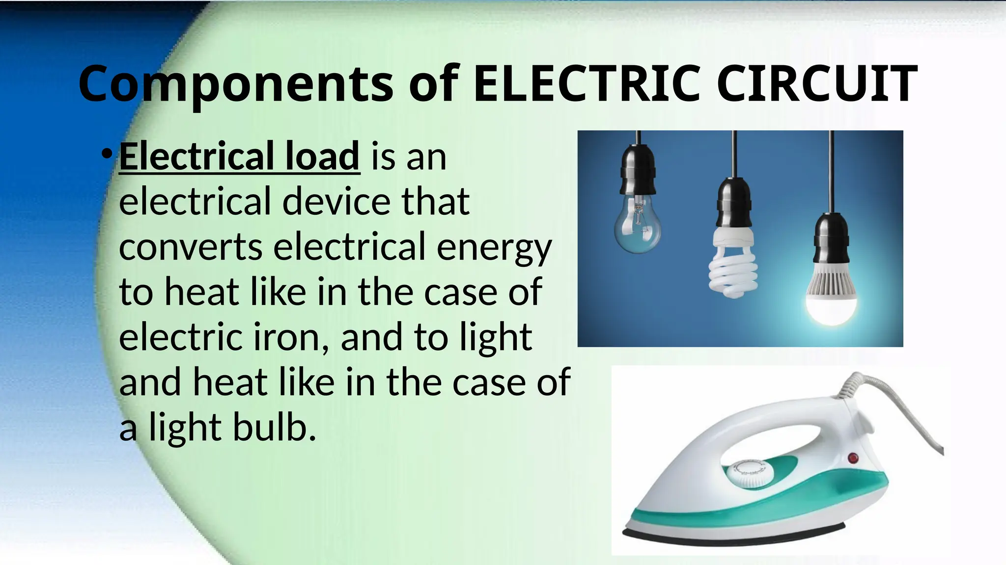
•Electrical load is an
electrical device that
converts electrical energy
to heat like in the case of
electric iron, and to light
and heat like in the case of
a light bulb.
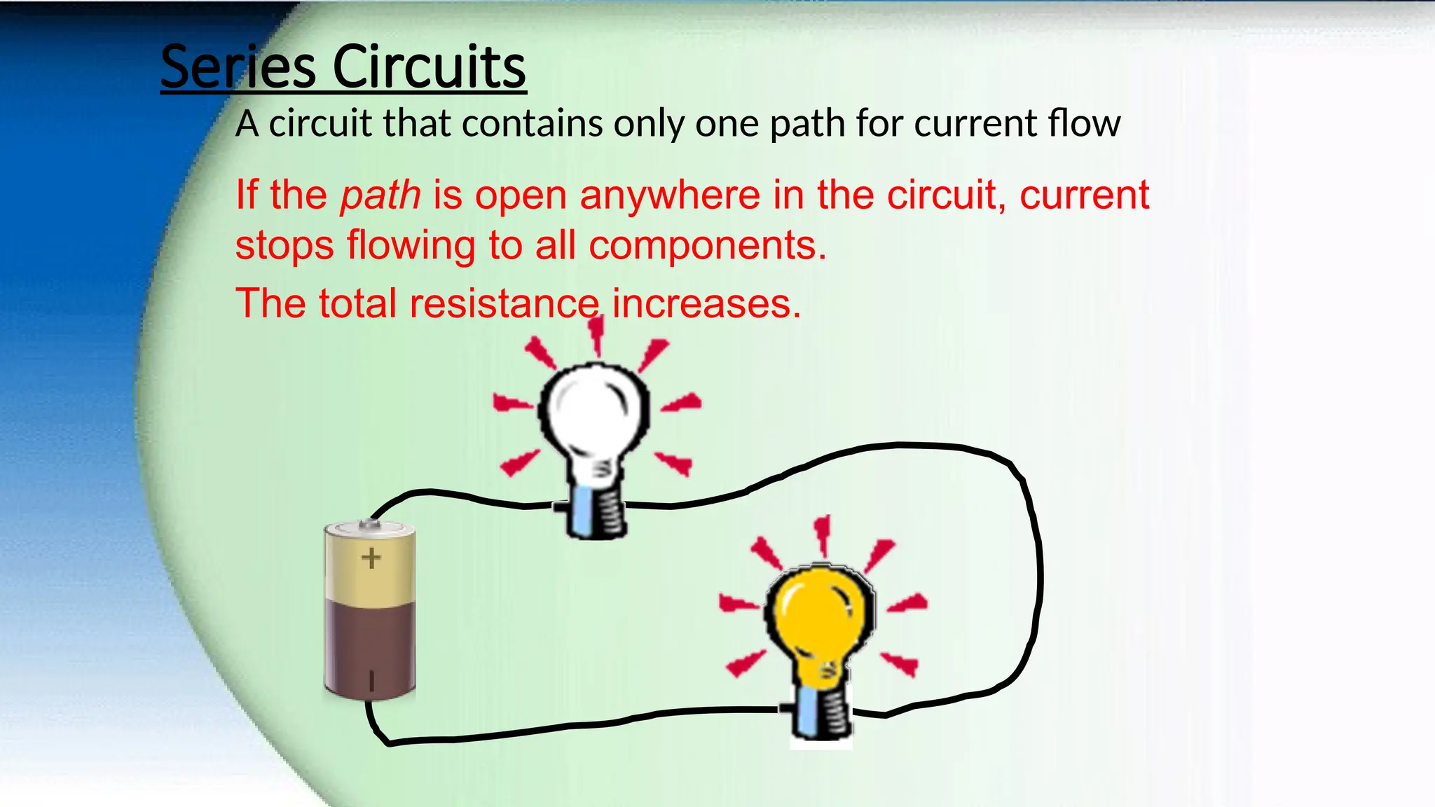
Series Circuits
A circuitthat contains only one path for current flow
If the path is open anywhere in the circuit, current
stops flowing to all components.
The total resistance increases.
11.
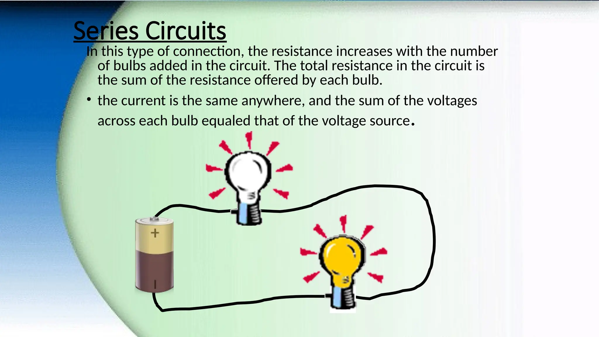
Series Circuits
In thistype of connection, the resistance increases with the number
of bulbs added in the circuit. The total resistance in the circuit is
the sum of the resistance offered by each bulb.
• the current is the same anywhere, and the sum of the voltages
across each bulb equaled that of the voltage source.
12.
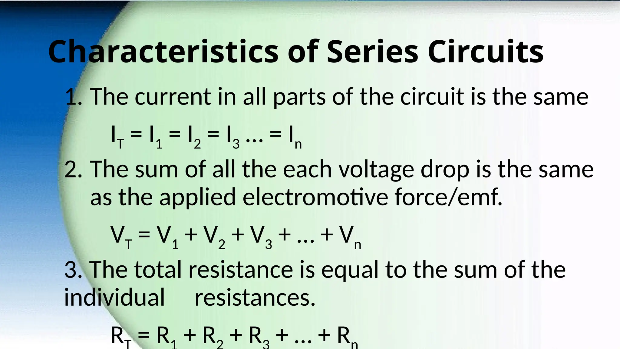
Characteristics of SeriesCircuits
1. The current in all parts of the circuit is the same
IT = I1 = I2 = I3 … = In
2. The sum of all the each voltage drop is the same
as the applied electromotive force/emf.
VT = V1 + V2 + V3 + … + Vn
3. The total resistance is equal to the sum of the
individual resistances.
R = R + R + R + … + R
13.
Advantages of UsingSeries Circuits
1. A series connection does not overheat easily. For a given
circuit of two loads, the amount of current passing through
each load is constant. If you add more loads, the amount of
current passing through in all the loads is still constant.
However, the amount of current in a circuit with two loads
is higher than the amount of current in a circuit with more
than two loads. Meaning, the more loads connected in
series circuit the amount of current reduces.
14.
Advantages of UsingSeries Circuits
2. In a series circuit, there is the only one path for
the current to flow from the voltage source to
the different loads. It would be easy to connect
and disconnect new load.
3. Since series circuit is less likely to overheat,
there is no need to use expensive, thick wires.
15.
Disadvantages of UsingSeries
Circuits
1. If one of the light bulbs is damaged or removed
in a series connection, all other light bulbs in the
circuit will not light too. This is because the point
where the bulb is damaged or removed causes the
circuit to open, resulting to discontinue the flow of
current in the circuit.
16.
Disadvantages of UsingSeries
Circuits
2. The addition of more light bulbs in series circuit causes
a decrease in the brightness of the bulbs. Given a fixed
amount of voltage supplied by the voltage source, the
more bulbs are added would mean more bulbs will share
the available electrical energy to be converted to light
energy.
3. The loads in a series circuit are difficult to control
individually. When the switch is off, all loads in the circuit
will not function anymore.
4. It is difficult to identify the damaged bulb in the circuit.
17.
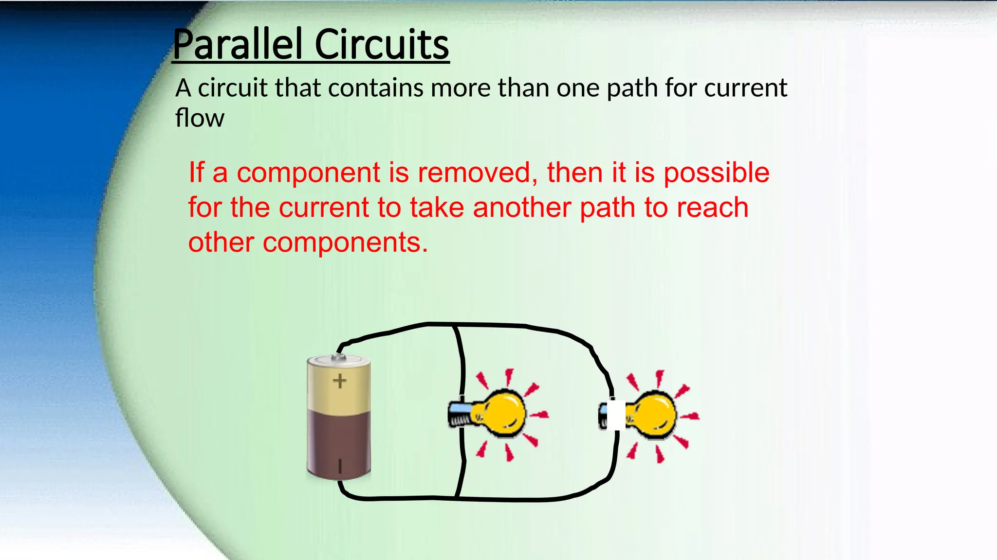
Parallel Circuits
A circuitthat contains more than one path for current
flow
If a component is removed, then it is possible
for the current to take another path to reach
other components.
18.
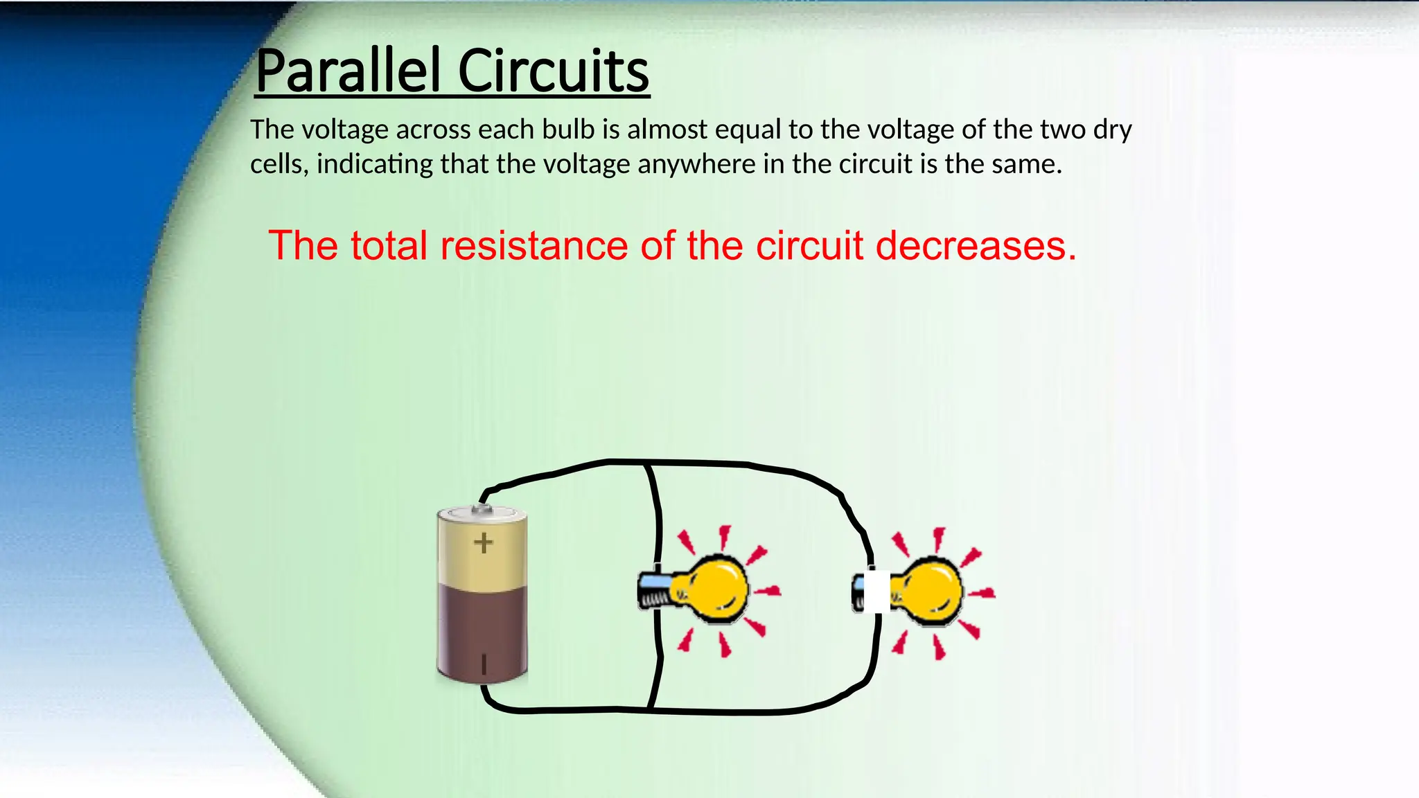
Parallel Circuits
The voltageacross each bulb is almost equal to the voltage of the two dry
cells, indicating that the voltage anywhere in the circuit is the same.
The total resistance of the circuit decreases.
19.
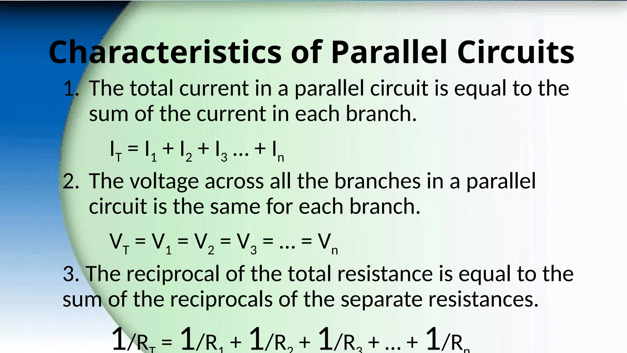
Characteristics of ParallelCircuits
1. The total current in a parallel circuit is equal to the
sum of the current in each branch.
IT = I1 + I2 + I3 … + In
2. The voltage across all the branches in a parallel
circuit is the same for each branch.
VT = V1 = V2 = V3 = … = Vn
3. The reciprocal of the total resistance is equal to the
sum of the reciprocals of the separate resistances.
1/R = 1/R + 1/R + 1/R + … + 1/R
20.
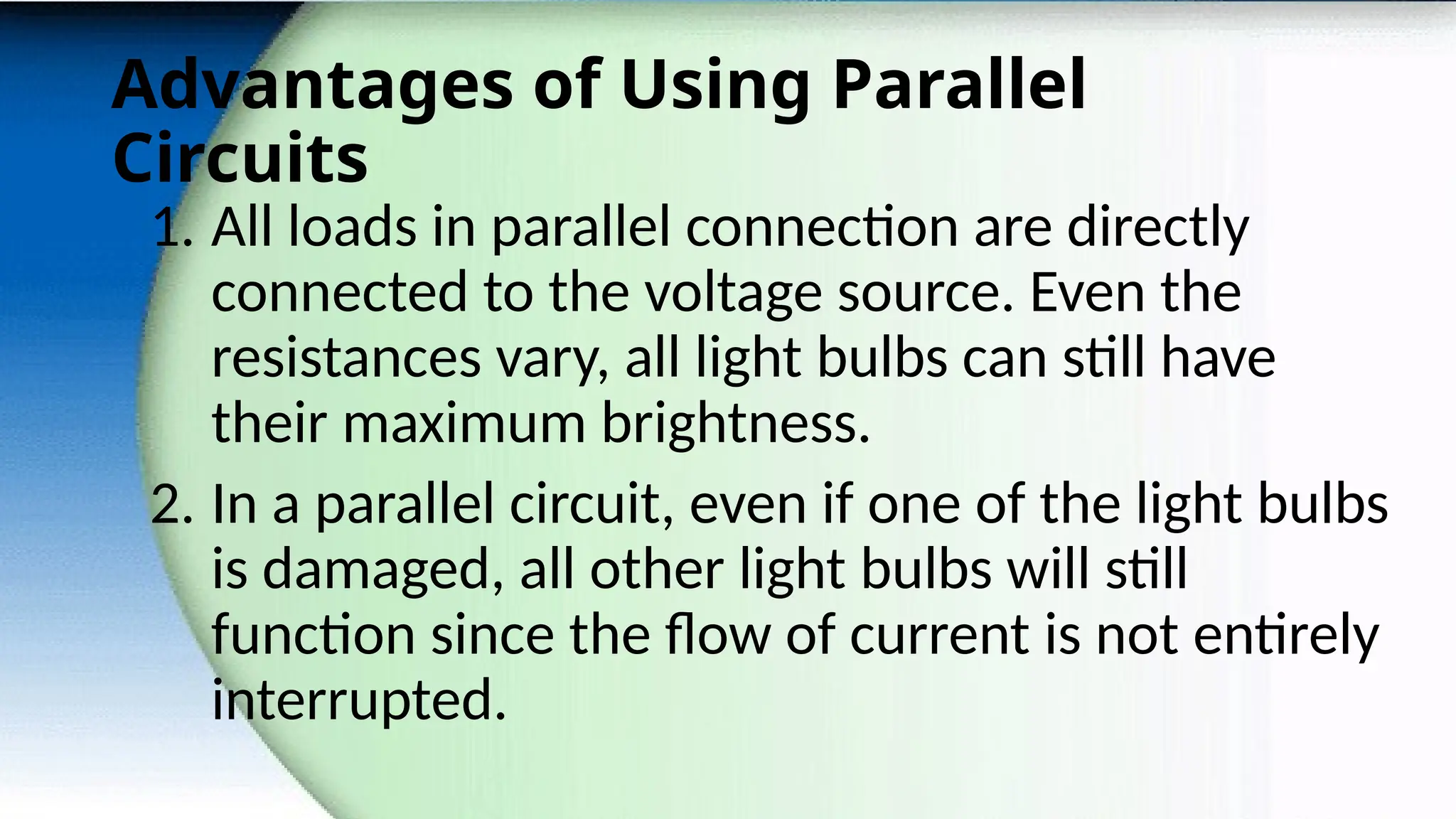
Advantages of UsingParallel
Circuits
1. All loads in parallel connection are directly
connected to the voltage source. Even the
resistances vary, all light bulbs can still have
their maximum brightness.
2. In a parallel circuit, even if one of the light bulbs
is damaged, all other light bulbs will still
function since the flow of current is not entirely
interrupted.
21.
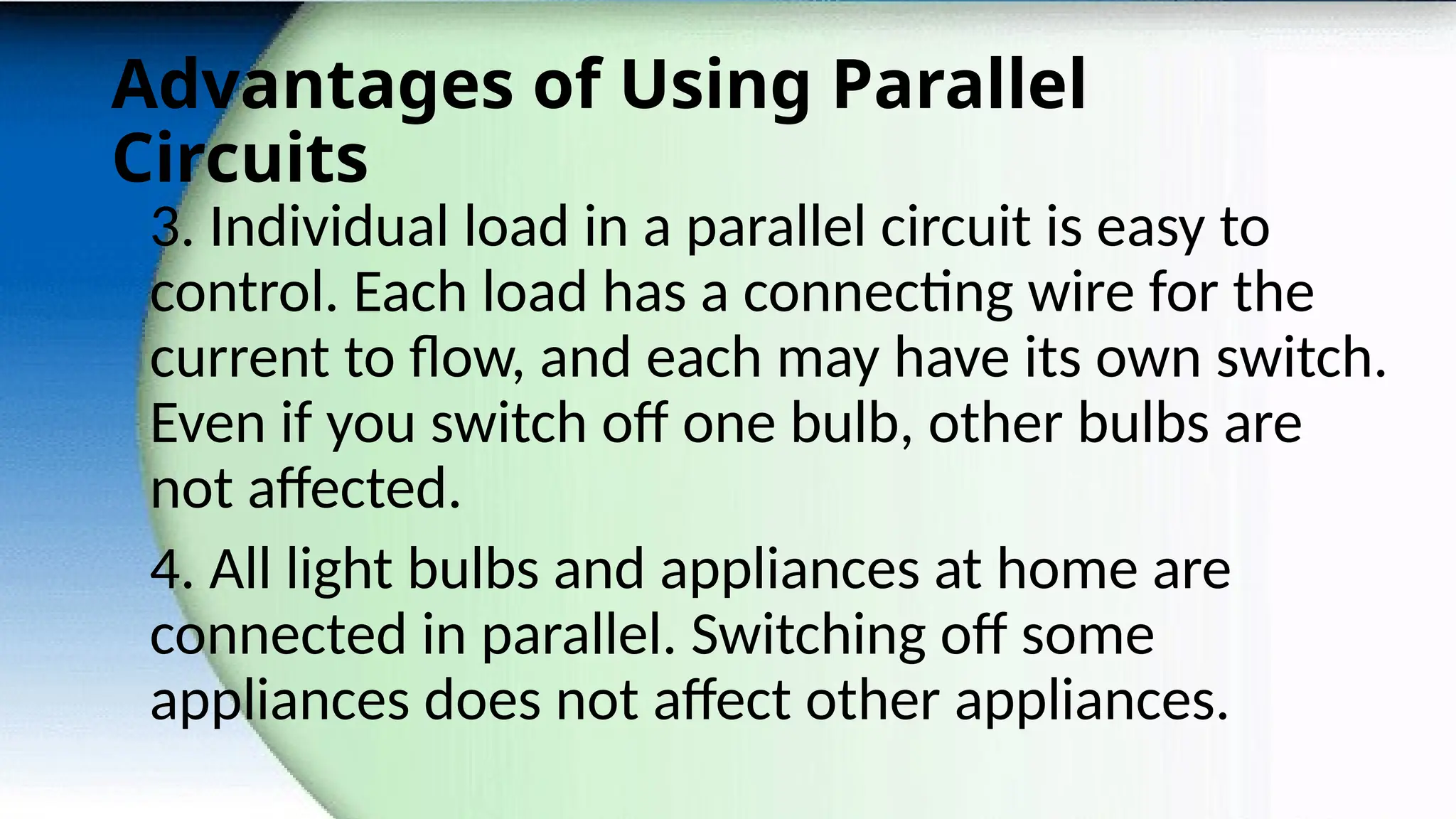
Advantages of UsingParallel
Circuits
3. Individual load in a parallel circuit is easy to
control. Each load has a connecting wire for the
current to flow, and each may have its own switch.
Even if you switch off one bulb, other bulbs are
not affected.
4. All light bulbs and appliances at home are
connected in parallel. Switching off some
appliances does not affect other appliances.
22.
Disadvantages of UsingParallel Circuits
1. Overloading may happen if appliances are
simultaneously used at home. With more loads,
total resistance decreases resulting to excessive,
large amount of current that would pass through
the conducting wires. Consequently, overheating
of wires takes place which may lead to fire.
23.
Disadvantages of UsingParallel Circuits
2. A parallel connection is difficult to install,
maintain, and repair since large volume of
conducting wires is needed. When problem in the
connection occurs, it is difficult to identify which
loop among the many loops does not work.
3. It requires the use of several conducting wires
of varying sizes.
24.
Sample Problem (SeriesCircuits)
1. Let us assume that you have five appliances
connected in series. The refrigerator has a
resistance of 20 Ω, the TV set 10 Ω, the radio 5 Ω,
the flat iron 75 Ω and the electric stove 55 Ω. If
the circuit is connected to a direct current of
220V, what is
a. The total resistance on the circuit?
b. The total current?
c. The voltage drop in each appliances?
25.
Sample Problem (SeriesCircuits)
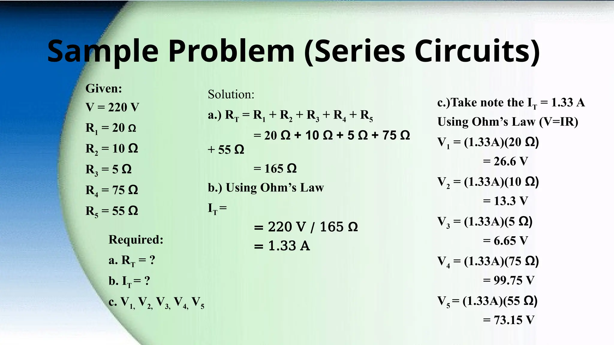
Given:
V = 220 V
R1 = 20 Ω
R2 = 10 Ω
R3 = 5 Ω
R4 = 75 Ω
R5 = 55 Ω
Required:
a. RT = ?
b. IT = ?
c. V1, V2, V3, V4, V5
26.
Sample Problem (SeriesCircuits)
Given:
V = 220 V
R1 = 20 Ω
R2 = 10 Ω
R3 = 5 Ω
R4 = 75 Ω
R5 = 55 Ω
Required:
a. RT = ?
b. IT = ?
c. V1, V2, V3, V4, V5
Solution:
a.) RT = R1 + R2 + R3 + R4 + R5
= 20 Ω + 10 Ω + 5 Ω + 75 Ω
+ 55 Ω
= 165 Ω
b.) Using Ohm’s Law
IT =
= 220 V / 165 Ω
= 1.33 A
c.)Take note the IT = 1.33 A
Using Ohm’s Law (V=IR)
V1 = (1.33A)(20 Ω)
= 26.6 V
V2 = (1.33A)(10 Ω)
= 13.3 V
V3 = (1.33A)(5 Ω)
= 6.65 V
V4 = (1.33A)(75 Ω)
= 99.75 V
V5 = (1.33A)(55 Ω)
= 73.15 V
27.
Sample Problem (ParallelCircuits)
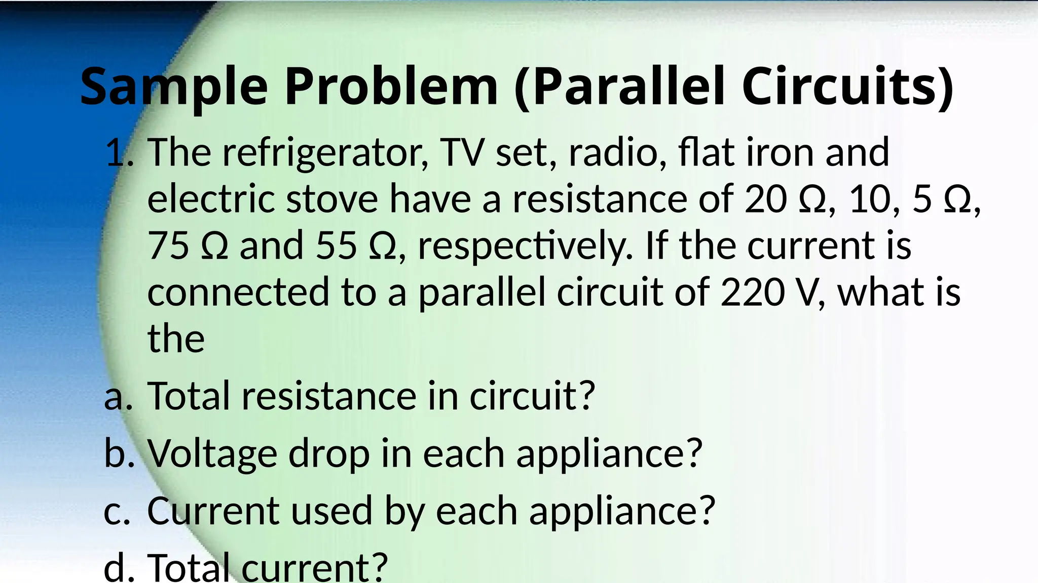
1. The refrigerator, TV set, radio, flat iron and
electric stove have a resistance of 20 Ω, 10, 5 Ω,
75 Ω and 55 Ω, respectively. If the current is
connected to a parallel circuit of 220 V, what is
the
a. Total resistance in circuit?
b. Voltage drop in each appliance?
c. Current used by each appliance?
d. Total current?
28.
Sample Problem (ParallelCircuits)
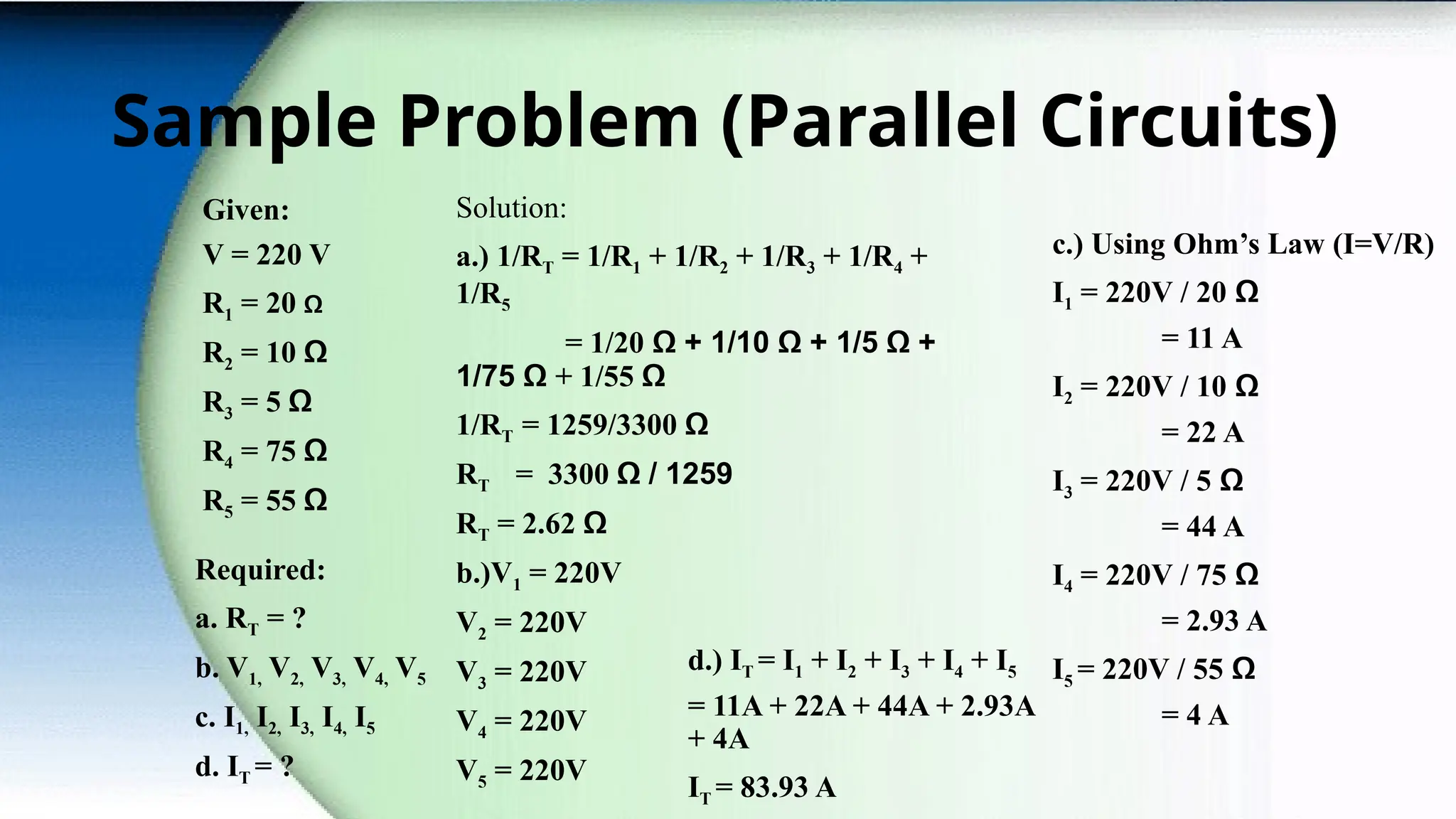
Given:
V = 220 V
R1 = 20 Ω
R2 = 10 Ω
R3 = 5 Ω
R4 = 75 Ω
R5 = 55 Ω
Required:
a. RT = ?
b. V1, V2, V3, V4, V5
c. I1, I2, I3, I4, I5
d. IT = ?
Solution:
a.) 1/RT = 1/R1 + 1/R2 + 1/R3 + 1/R4 +
1/R5
= 1/20 Ω + 1/10 Ω + 1/5 Ω +
1/75 Ω + 1/55 Ω
1/RT = 1259/3300 Ω
RT = 3300 Ω / 1259
RT = 2.62 Ω
b.)V1 = 220V
V2 = 220V
V3 = 220V
V4 = 220V
V5 = 220V
c.) Using Ohm’s Law (I=V/R)
I1 = 220V / 20 Ω
= 11 A
I2 = 220V / 10 Ω
= 22 A
I3 = 220V / 5 Ω
= 44 A
I4 = 220V / 75 Ω
= 2.93 A
I5 = 220V / 55 Ω
= 4 A
d.) IT = I1 + I2 + I3 + I4 + I5
= 11A + 22A + 44A + 2.93A
+ 4A
IT = 83.93 A
29.
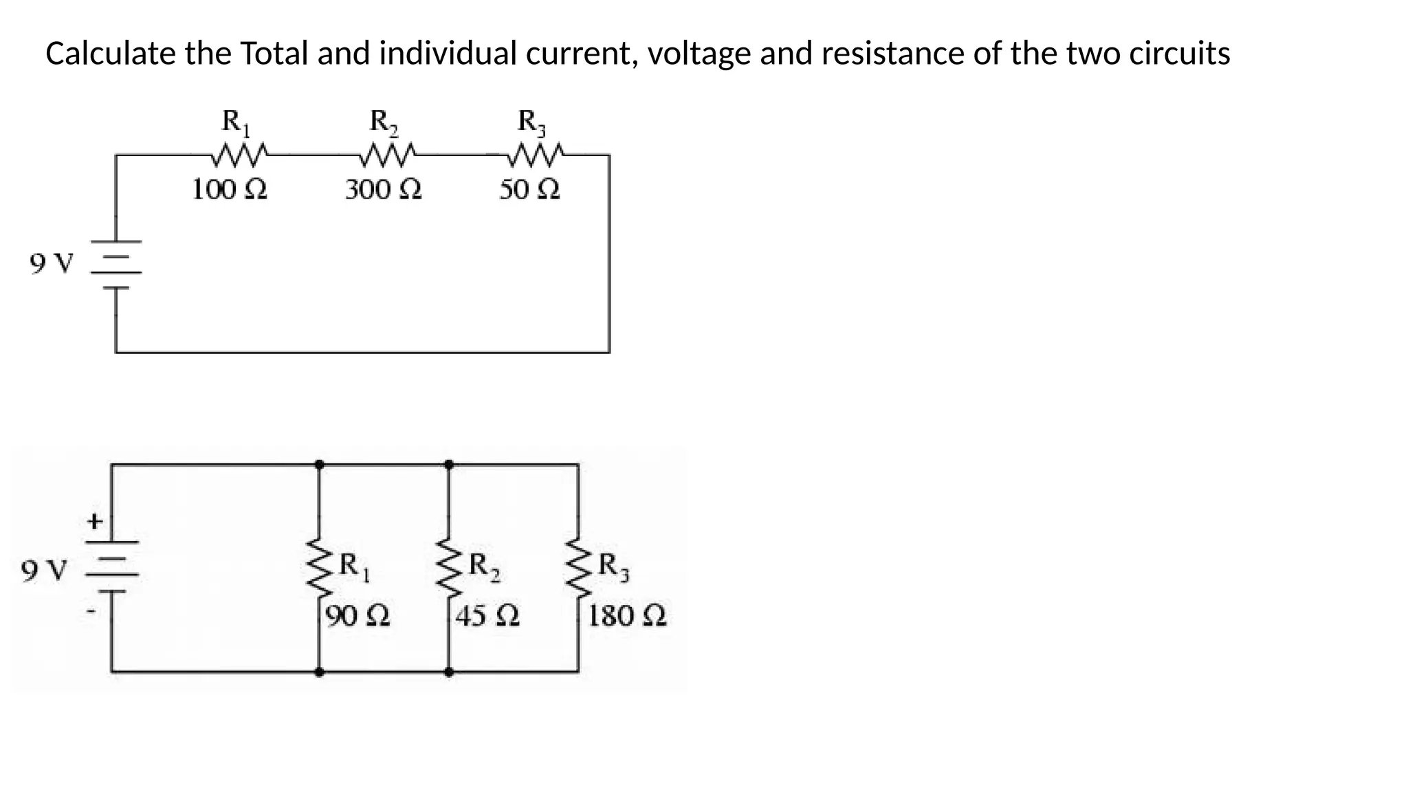
Calculate the Totaland individual current, voltage and resistance of the two circuits
30.
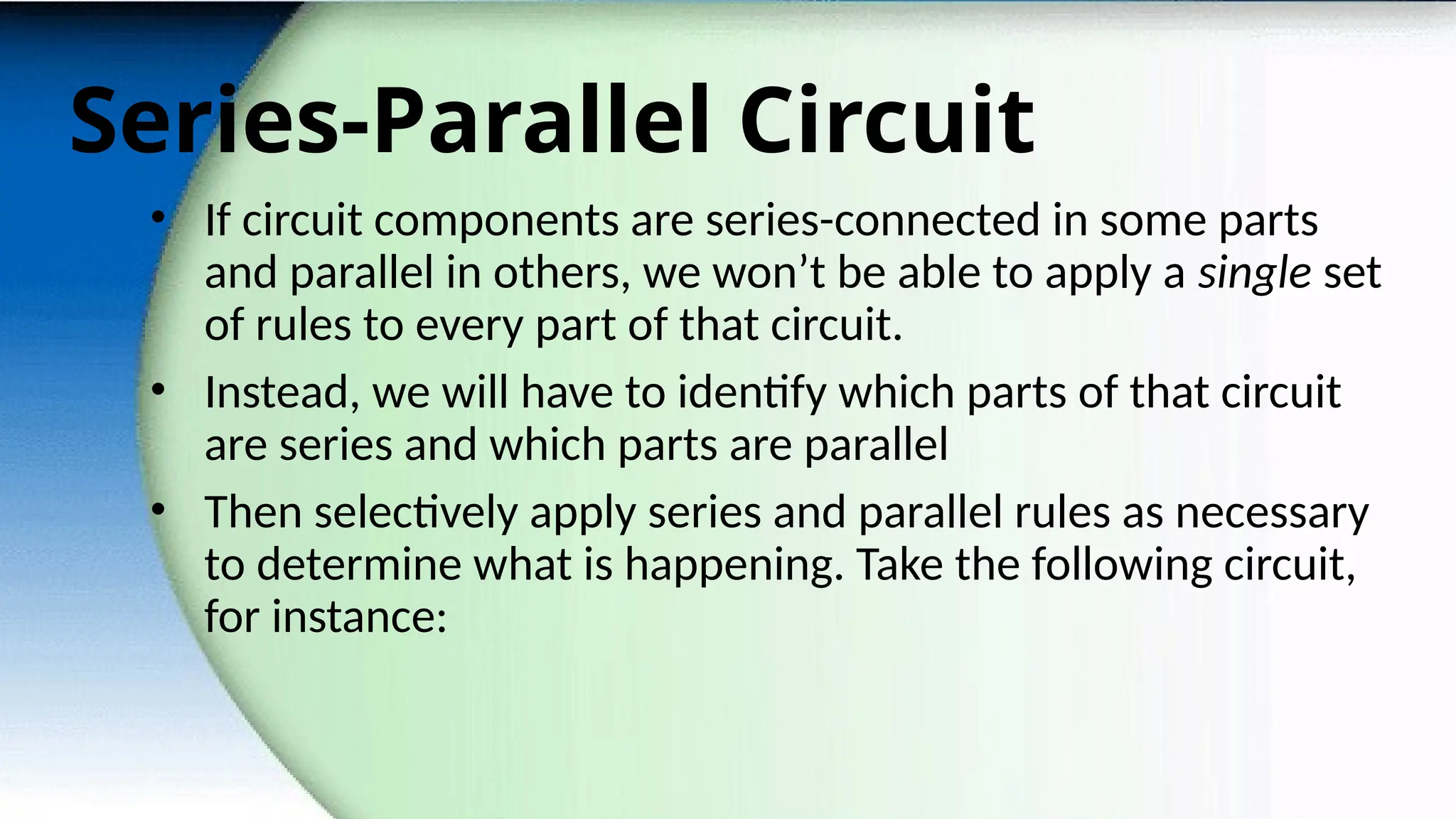
Series-Parallel Circuit
• Ifcircuit components are series-connected in some parts
and parallel in others, we won’t be able to apply a single set
of rules to every part of that circuit.
• Instead, we will have to identify which parts of that circuit
are series and which parts are parallel
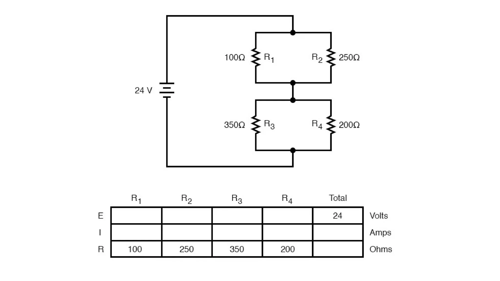
• Then selectively apply series and parallel rules as necessary
to determine what is happening. Take the following circuit,
for instance:
Editor's Notes
#4 Conventional Current vs. Electron Flow (Scientists vs. Engineers – since this is an engineering course, guess who wins?).