Download to read offline


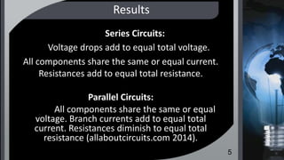


The document analyzes electrical values for series, parallel, and series-parallel circuits, emphasizing the need to apply distinct rules for each configuration. It covers calculations for voltages, currents, and resistance, and discusses Kirchhoff's current and voltage laws as fundamental principles for circuit analysis. The reflections illustrate practical applications and common observations regarding series and parallel circuits.


