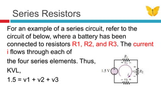
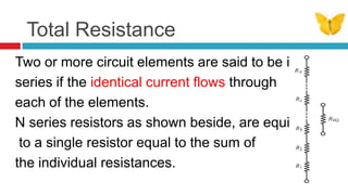
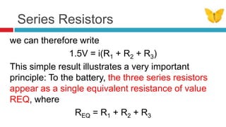
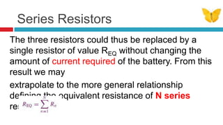
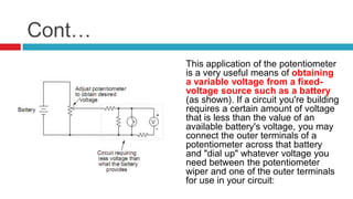
1. The document discusses series circuits and how voltage is divided among resistors in series. It explains that the total resistance of resistors in series is equal to the sum of the individual resistances.
2. A key concept covered is the voltage divider rule - the voltage across each resistor in a series circuit is directly proportional to the ratio of its resistance to the total resistance.
3. Applications of voltage dividers include using potentiometers (variable resistors) to obtain a variable output voltage from a fixed voltage source.
A series circuit is a circuit in which resistors are arranged in a chain, so the current has only one path to take. The current is the same through each resistor.
Electricity and Electromagnetism (experimental study)Raboon Redar
You’ll understand the way to calculate and measure resistance in parallel and series circuits by knowing two of the three values of voltage, current, or resistance. In this experiment, there are 3 resistors, 1 power supply and wires you need for connecting resistors to each other, then to power supply. You can measure each resistor by an ohmmeter, voltages by voltmeter and currents by amperemeter (ammeter), while all of them can be measured by a multimeter. Use a multimeter for measuring resistance for better accuracy.
The French Revolution, which began in 1789, was a period of radical social and political upheaval in France. It marked the decline of absolute monarchies, the rise of secular and democratic republics, and the eventual rise of Napoleon Bonaparte. This revolutionary period is crucial in understanding the transition from feudalism to modernity in Europe.
For more information, visit-www.vavaclasses.com
We all have good and bad thoughts from time to time and situation to situation. We are bombarded daily with spiraling thoughts(both negative and positive) creating all-consuming feel , making us difficult to manage with associated suffering. Good thoughts are like our Mob Signal (Positive thought) amidst noise(negative thought) in the atmosphere. Negative thoughts like noise outweigh positive thoughts. These thoughts often create unwanted confusion, trouble, stress and frustration in our mind as well as chaos in our physical world. Negative thoughts are also known as “distorted thinking”.
Synthetic Fiber Construction in lab .pptxPavel ( NSTU)
Synthetic fiber production is a fascinating and complex field that blends chemistry, engineering, and environmental science. By understanding these aspects, students can gain a comprehensive view of synthetic fiber production, its impact on society and the environment, and the potential for future innovations. Synthetic fibers play a crucial role in modern society, impacting various aspects of daily life, industry, and the environment. ynthetic fibers are integral to modern life, offering a range of benefits from cost-effectiveness and versatility to innovative applications and performance characteristics. While they pose environmental challenges, ongoing research and development aim to create more sustainable and eco-friendly alternatives. Understanding the importance of synthetic fibers helps in appreciating their role in the economy, industry, and daily life, while also emphasizing the need for sustainable practices and innovation.
Model Attribute Check Company Auto PropertyCeline George
In Odoo, the multi-company feature allows you to manage multiple companies within a single Odoo database instance. Each company can have its own configurations while still sharing common resources such as products, customers, and suppliers.
2. Series Resistors and Voltage Divider Series Resistors and the Voltage Divider Rule Although electrical circuits can take rather complicated forms, even the most involved circuits can be reduced to combinations of circuit elements in parallel an in series. Thus, it is important that you become acquainted with parallel and series circuits as early as possible, even before formally approaching the topic of network analysis. Parallel and series circuits have a direct relationship with Kirchhoff’s laws.
3. Objective The objective of this section and the next is to illustrate two common circuits based on series and parallel combinations of resistors: the voltage and current dividers. These circuits form the basis of all network analysis; it is therefore important to master these topics as early as possible.
4. Series Resistors For an example of a series circuit, refer to the circuit of below, where a battery has been connected to resistors R1, R2, and R3. The current i flows through each of the four series elements. Thus, by KVL, 1.5 = v1 + v2 + v3
5. Total Resistance Two or more circuit elements are said to be in series if the identical current flowsthrough each of the elements. N series resistors as shown beside, are equivalent to a single resistor equal to the sum of the individual resistances.
6. KVL A series of carefully conducted experimental observations regarding the nature of voltages in an electric circuit led Kirchhoff to the formulation of this laws, Kirchhoff’s voltage law, or KVL. The principle underlying KVL is that no energy is lost or created in an electric circuit; in circuit terms, the sum of all voltages associated with sources must equal the sum of the load voltages, so that the net voltage around a closed circuit is zero. If this were not the case, we would need to find a physical explanation for the excess (or missing) energy not accounted for in the voltages around a circuit.
7. Cont… Kirchhoff’s voltage law may be stated in the form below vn are the individual voltages around the closed circuit and in the other conventional forms as seen below: Vs = V1+ V2+ V3+… +Vn Vs – (V1+ V2+ V3+… +Vn) = 0
8. Series Resistors By applying KVL to the earlier circuit of 3 resistors, you can verify that the sum of the voltages across the three resistors equals the voltage externally provided by the battery: 1.5V = v1 + v2 + v3 and since, according to Ohm’s law, the separate voltages can be expressed by the relations v1 = iR1, v2 = iR2 ,v3 = iR3
9. Series Resistors we can therefore write 1.5V = i(R1 + R2 + R3) This simple result illustrates a very important principle: To the battery, the three series resistors appear as a single equivalent resistance of value REQ, where REQ = R1 + R2 + R3
10. Series Resistors The three resistors could thus be replaced by a single resistor of value REQ without changing the amount of current required of the battery. From this result we may extrapolate to the more general relationship defining the equivalent resistance of N series resistors:
11. Voltage Divider This concept seen previously very closely tied to series resistors is that of the voltage divider. This terminology originates from the observation that the source voltage divides among the three resistors according to KVL. If we now observe that the series current, i, is given by:
12. Voltage Divider we can write each of the voltages across the resistors as: That is: The voltage across each resistor in a series circuit is directly proportional to the ratio of its resistance to the total series resistance of the circuit.
13. Voltage Divider applications Voltage dividers find wide application in electric meter circuits, where specific combinations of series resistors are used to "divide" a voltage into precise proportions as part of a voltage measurement device.
14. Cont… One device frequently used as a voltage-dividing component is the potentiometer, which is a resistor with a movable element positioned by a manual knob or lever. The movable element, typically called a wiper, makes contact with a resistive strip of material (commonly called the slidewire if made of resistive metal wire) at any point selected by the manual control:
15. Cont… The wiper contact is the left-facing arrow symbol drawn in the middle of the vertical resistor element. As it is moved up, it contacts the resistive strip closer to terminal 1 and further away from terminal 2, lowering resistance to terminal 1 and raising resistance to terminal 2. As it is moved down, the opposite effect results. The resistance as measured between terminals 1 and 2 is constant for any wiper position.
16. Types of pots Some linear potentiometers are actuated by straight-line motion of a lever or slide button. Others, like the one depicted in the previous illustration, are actuated by a turn-screw for fine adjustment ability. The latter units are sometimes referred to as trimpots, because they work well for applications requiring a variable resistance to be "trimmed" to some precise value. It should be noted that not all linear potentiometers have the same terminal assignments as shown in this illustration. With some, the wiper terminal is in the middle, between the two end terminals.
17. The potentiometer as a variable voltage divider Just like the fixed voltage divider, the potentiometer's voltage division ratio is strictly a function of resistance and not of the magnitude of applied voltage. In other words, if the potentiometer knob or lever is moved to the 50 percent (exact center) position, the voltage dropped between wiper and either outside terminal would be exactly 1/2 of the applied voltage, no matter what that voltage happens to be, or what the end-to-end resistance of the potentiometer is. In other words, a potentiometer functions as a variable voltage divider where the voltage division ratio is set by wiper position.
18. Cont… This application of the potentiometer is a very useful means of obtaining a variable voltage from a fixed-voltage source such as a battery (as shown). If a circuit you're building requires a certain amount of voltage that is less than the value of an available battery's voltage, you may connect the outer terminals of a potentiometer across that battery and "dial up" whatever voltage you need between the potentiometer wiper and one of the outer terminals for use in your circuit:
19. Review Given the following series circuit, taking into account the sign of the voltage drops we should be able to note that the sum of all voltages in the closed circuit is zero.
20. Troubleshooting We need to realize that electric circuit components can fail and thus knowing how to analyze such a circuit is of great importance. The two import faults that can happen in a simple series circuit are either opens or shorts. Anopenis when a disconnection to a circuit component (resistor) has occurred and therefore disrupts the flow of current. This can happen as a result of aging of the component, cold solder connections, dislocation of terminals, excessive current leading to burning open, etc. When this occurs, we have to resolve the circuit to its original operational state. Shown is an operational circuit that will experience one fault at a time of its componets– an open.
21. Open – Voltage source off Assuming that we have a control switch somewhere in the circuit and this switch is in the off position. We expect to see that No current will flow in the circuit No voltage drops across the circuit components
23. A resistor is open If one of the resistors in series burns open, then we expect the following conditions No current flow Total resistance is infinite Total source voltage drops across the burnt-out resistor No voltage drop across the good resistors. Note that the above conditions would happen in the case of any other single open fault.. Eg resistor two open others okay, or resistor three and others okay…
24. Short Resistor Resistors likewise can have their internal resistances change significantly far below their expected values, sometimes an external component may “short” them out. For a “dead short”, the internal resistance is taken to be zero ohms. Let us see what happens to our circuit if a single short happens…
25. Expected Voltages If one of the resistors in series shorts, then we expect the following conditions Increase in total current flow Total resistance is reduced by value of shorted resistor Total source voltage drops across the good resistors proportionately to their resistance values Note that the above conditions would happen in the case of any other single short fault.. Eg resistor two shorts others okay, or resistor three and others okay…