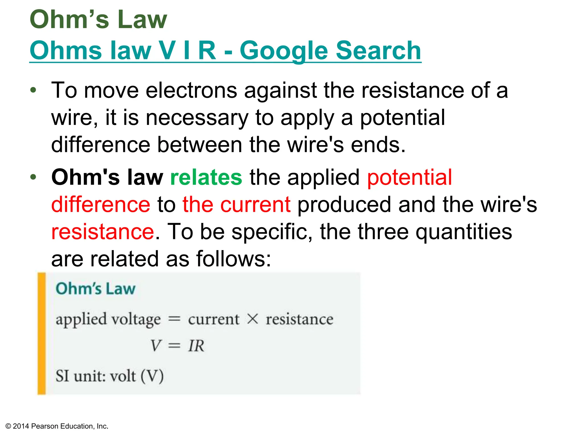
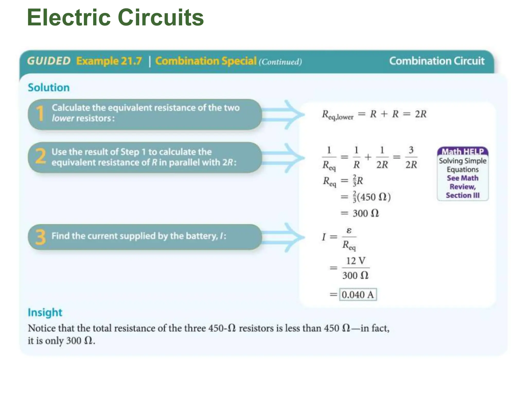
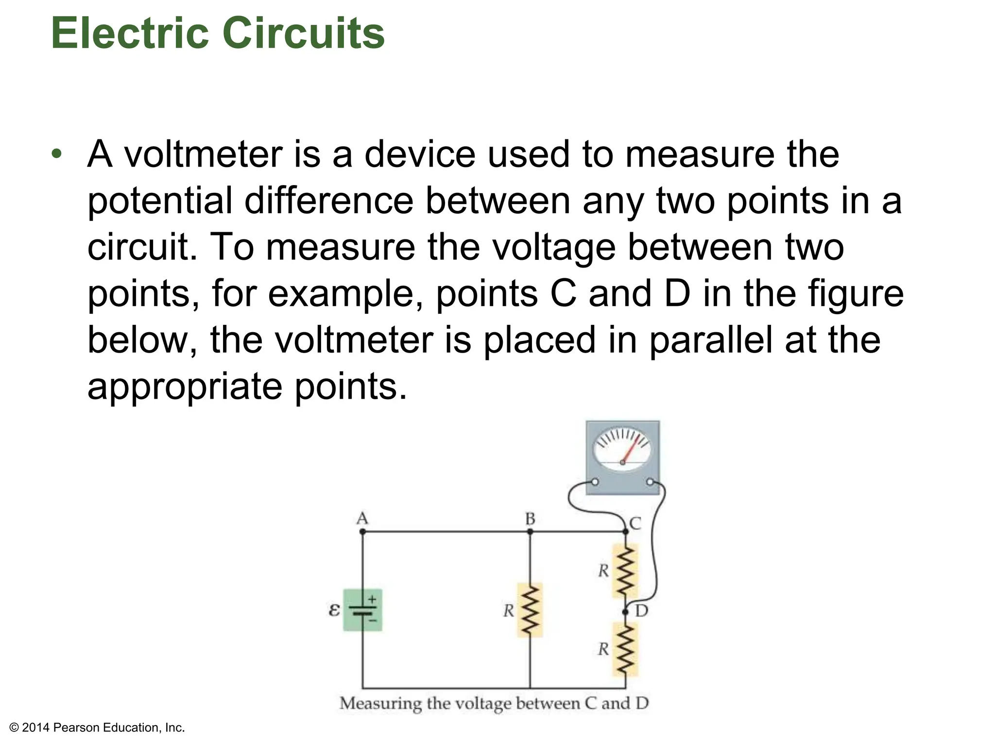
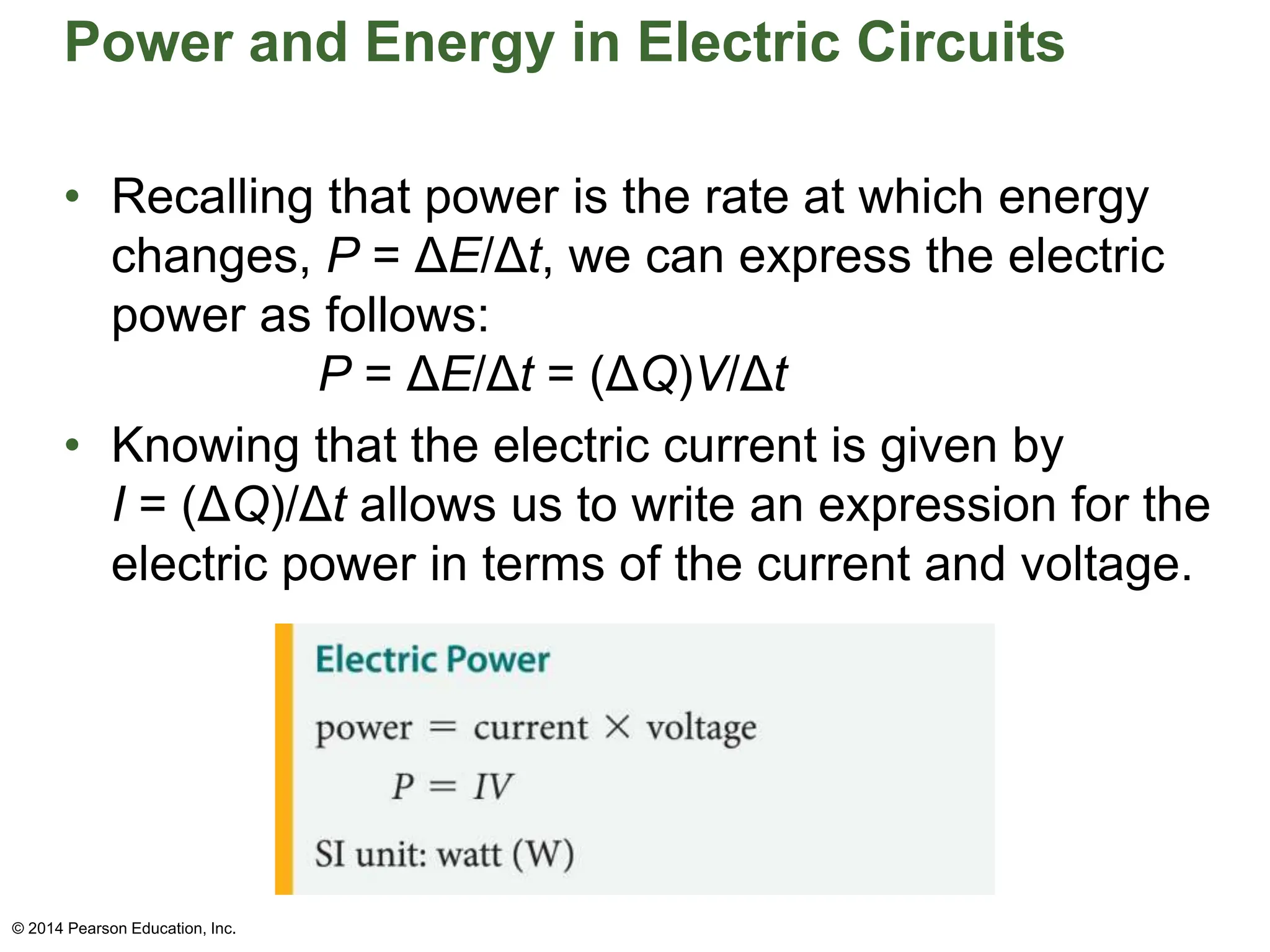
Bell Ringer Activity
Think-Pair-Share
Everyday Physics in your life:
Imagine you have a circuit with a light bulb
connected to a battery. Describe in your own
words what you think happens to the flow of
electric charge and the potential difference as
the circuit is completed by closing the switch.
How do you think the current and potential
difference relate to each other in this scenario?
© 2014 Pearson Education,Inc.
Learning Outcomes
1. Solve problems related to
equivalent resistance.
2. Design an experiment to verify
Ohm's Law.
3. Apply your understanding of
resistance to real life.
SUCCESS CRITERIA
I can define resistance.
I can state Ohm’s Law.
I can interpret experimental data to
determine the relationship between
voltage, current, and resistance.
I can relate the concept of resistance to
real life (UAE)
• Oral presentation : Resistors and resistance
• Write From Scratch Using Grammarly's
Generative AI (youtube.com)
• Questions /Self assess.
Ohm’s Law
Ohms law V I R - Google Search
• To move electrons against the resistance of a
wire, it is necessary to apply a potential
difference between the wire's ends.
• Ohm's law relates the applied potential
difference to the current produced and the wire's
resistance. To be specific, the three quantities
are related as follows:
© 2014 Pearson Education, Inc.
Ohm’s Law
• Ohm's law is named for the German physicist
Georg Simon Ohm (1789–1854).
• Rearranging Ohm's law to solve for the resistance,
we find
R = V/I
• From this expression, it is clear that resistance has
units of volts per amp. A resistance of 1 volt per
amp defines a new unit—the ohm. The Greek
letter omega (Ω) is used to designate the ohm.
Thus,
1 Ω = 1 V/A
• A device for measuring resistance is called an
ohmmeter.
© 2014 Pearson Education, Inc.
I –We –YOU strategy
• A potential difference of 24 V is applied to a 150
Ω resistor. How much current flows through the
resistor ?
Given Equation
Potential difference= 24 V V = R x I
R =150 Ω I = V /R
I = ?? I = 24 /150 = 0.16 A
© 2014 Pearson Education, Inc.
WE – Group work
• A potential difference of 16 V is applied to a
resistor whose resistance is 220 Ω .What is the
current that flows through the resistor?
© 2014 Pearson Education, Inc.
YOU – Check your channel on teams!
Question 1: gas group
What voltage is required to produce a current of
1.8 A through a 140 Ω resistor?
Question 2:Liquid group
When a potential difference of 18 V is applied to a
given wire ,the wire conducts 0.35 A of current.
What is the resistance of the wire?
Question 3:Solid group
A current of 0.2A passes through a 1.4 kΩ resistor.
What is the voltage across it?
© 2014 Pearson Education, Inc.
Bell Ringer Activity
Think-Pair-Share
Use Padlet the answer the following questions:
Everyday Physics in your life:
1. How does the function of a resistor differ
from other components in a circuit?
2. Describe the relationship between voltage,
current, and resistance using Ohm's Law.
• Series and Parallel Circuits | Electricity | Physics
| FuseSchool (youtube.com)
Check Point (Self-Assessment)
1.In a parallel circuit, what is true about the
potential difference across each component?
a. It is different for each component
b. It is equal for each component
c. It varies based on resistance
2.True/False
Total voltage in series circuits is not shared
between components.
3. Explain how does the current vary in series
circuits.
EMSAT ‘STYLE’ question : Pair work
Electric Circuits
• Electric circuits often contain a number of
resistors connected in various ways.
• One way resistors can be connected is end to
end. Resistors connected in this way are said to
form a series circuit. The figure below shows
three resistors R1, R2, and R3, connected in
series.
© 2014 Pearson Education, Inc.
Electric Circuits
• The three resistors acting together have the same
effect—that is, they draw the same current—as a single
resistor, which is referred to as the equivalent resistor, Req.
• This equivalence is illustrated in the figure below.
• The equivalent resistor has the same current, I, flowing
through it as each resistor in the original circuit.
© 2014 Pearson Education, Inc.
Electric Circuits
• When resistors are connected in series, the
equivalent resistance is simply the sum of the
individual resistances.
• In our case, with three resistors, we have
Req = R1 + R2 + R3
• In general, the equivalent resistance of resistors
in series is the sum of all the resistances that are
connected together:
© 2014 Pearson Education, Inc.
Electric Circuits
• The following example illustrates the functioning
of a series circuit.
© 2014 Pearson Education, Inc.
Electric Circuits
© 2014 Pearson Education, Inc.
Electric Circuits
• Resistors that are connected across the same
potential difference are said to form a parallel
circuit.
• An example of three resistors connected in parallel
is shown the figure below.
© 2014 Pearson Education, Inc.
Electric Circuits
• In a case like this, the electrons have three parallel paths
through which they can flow—like parallel lanes on the
highway.
• The three resistors acting together draw the same current
as a single equivalent resistor, Req, as indicated in the
figure below.
© 2014 Pearson Education, Inc.
Electric Circuits
• When resistors are connected in parallel, the
reciprocal of the equivalent resistance is equal
to the sum of the reciprocals of the individual
resistances. Thus, for our circuit of three
resistors, we have
1/Req = 1/R1 + 1/R2 + 1/R3
• In general, the inverse equivalent resistance is
equal to the sum of all of the individual inverse
resistances:
© 2014 Pearson Education, Inc.
Electric Circuits
• As an example of parallel resistors, consider a
circuit with two identical resistors, R, connected in
parallel. The equivalent resistance in this case is
1/Req = 1/R + 1/R
1/Req = 2/R
© 2014 Pearson Education, Inc.
WE – Group work
© 2014 Pearson Education, Inc.
Calculate the total resistance of the following
resistors.
1. What is the equivalent resistance if 3Ω,
20Ω and 32Ω are connected in series.
2. What is the equivalent resistance if
34 Ω and 20 Ω are connected in parallel.
You –Check your Channel on Teams!
Calculate the total resistance in each of the
following circuit
© 2014 Pearson Education, Inc.
Gas group Liquid group
Solid group
Electric Circuits
• The following example illustrates the functioning
of a parallel circuit.
© 2014 Pearson Education, Inc.
Electric Circuits
Electric Circuits
• By considering the resistors in pairs or groups that
are connected in parallel or in series, you can
reduce the entire circuit to one equivalent circuit.
This method is applied in the following example.
© 2014 Pearson Education, Inc.
Electric Circuits
Electric Circuits
• A voltmeter is a device used to measure the
potential difference between any two points in a
circuit. To measure the voltage between two
points, for example, points C and D in the figure
below, the voltmeter is placed in parallel at the
appropriate points.
© 2014 Pearson Education, Inc.
Power and Energy in Electric Circuits
• The power delivered by an electric circuit increases
with both the current and the voltage. Increase
either, and the power increases.
• When a ball falls in a gravitational field, there is a
change in gravitational potential energy. Similarly,
when an amount of charge, ΔQ, moves across a
potential difference, V, there is a change in
electrical potential energy, ΔPE, given by
ΔPE = (ΔQ)V
© 2014 Pearson Education, Inc.
Power and Energy in Electric Circuits
• Recalling that power is the rate at which energy
changes, P = ΔE/Δt, we can express the electric
power as follows:
P = ΔE/Δt = (ΔQ)V/Δt
• Knowing that the electric current is given by
I = (ΔQ)/Δt allows us to write an expression for the
electric power in terms of the current and voltage.
© 2014 Pearson Education, Inc.
Power and Energy in Electric Circuits
• Thus, the electric power used by a device is equal
to the current times the voltage. For example, a
current of 1 amp flowing across a potential
difference of 1 V produces a power of 1 W.
• The following example provides another example
of how the electric power is calculated.
© 2014 Pearson Education, Inc.
Power and Energy in Electric Circuits
• The equation P = IV applies to any electrical
system. In the special case of a resistor, the electric
power is dissipated in the form of heat and light, as
shown in the figure, where the electric power
dissipated in an electric space heater.
© 2014 Pearson Education, Inc.
Power and Energy in Electric Circuits
• Applying Ohm's law, V = IR, which deals with resistors,
we can express the power dissipated in a resistor as
follows:
P = IV = I(IR) = I2R
• Similarly, solving Ohm's law for the current, I = V/R, and
substituting that result gives an alternative expression for
the power dissipated in a resistor:
P = IV = (V/R)V = V2/R
• All three equations for power are valid. The first, P = IV,
applies to all electrical systems. The other two
(P = I2R and P = V2/R) are specific to resistors, which is
why the resistance, R, appears in those equations.
© 2014 Pearson Education, Inc.
Power and Energy in Electric Circuits
• The filament of an incandescent lightbulb is
basically a resistor inside a sealed, evacuated
tube. The filament gets so hot that it glows, just
like the heating coil on a stove or the coils in a
space heater.
• The power dissipated in the filament determines
the brightness of the lightbulb. The higher the
power, the brighter the bulb. This basic concept is
applied in the example on the next slide.
© 2014 Pearson Education, Inc.
Power and Energy in Electric Circuits
© 2014 Pearson Education, Inc.
Power and Energy in Electric Circuits
• The local electric company bills consumers for the
electricity they use each month. To do this, they
use a convenient unit for measuring electric
energy called the kilowatt-hour.
• Recall that a kilowatt is 1000 W, or equivalently,
1000 J/s. Similarly, an hour is 3600 s. Combining
these results, we see that a kilowatt-hour is equal
to 3.6 million joules of energy:
1 kWh = (1000 J/s)(3600 s) = 3.6 x 10⁶ J
© 2014 Pearson Education, Inc.
Power and Energy in Electric Circuits
• The figure below shows the type of meter used
to measure the electrical energy consumption of
a household, as well as the typical bill.
© 2014 Pearson Education, Inc.
Power and Energy in Electric Circuits
• The following example illustrates how the cost of
electrical energy is calculated.
© 2014 Pearson Education, Inc.
Power and Energy in Electric Circuits

ch_21_PPT_lecture for physics resitor in series and parallel circuit

  • 1.
    Bell Ringer Activity Think-Pair-Share EverydayPhysics in your life: Imagine you have a circuit with a light bulb connected to a battery. Describe in your own words what you think happens to the flow of electric charge and the potential difference as the circuit is completed by closing the switch. How do you think the current and potential difference relate to each other in this scenario? © 2014 Pearson Education,Inc.
  • 2.
    Learning Outcomes 1. Solveproblems related to equivalent resistance. 2. Design an experiment to verify Ohm's Law. 3. Apply your understanding of resistance to real life.
  • 3.
    SUCCESS CRITERIA I candefine resistance. I can state Ohm’s Law. I can interpret experimental data to determine the relationship between voltage, current, and resistance. I can relate the concept of resistance to real life (UAE)
  • 4.
    • Oral presentation: Resistors and resistance • Write From Scratch Using Grammarly's Generative AI (youtube.com) • Questions /Self assess.
  • 5.
    Ohm’s Law Ohms lawV I R - Google Search • To move electrons against the resistance of a wire, it is necessary to apply a potential difference between the wire's ends. • Ohm's law relates the applied potential difference to the current produced and the wire's resistance. To be specific, the three quantities are related as follows: © 2014 Pearson Education, Inc.
  • 6.
    Ohm’s Law • Ohm'slaw is named for the German physicist Georg Simon Ohm (1789–1854). • Rearranging Ohm's law to solve for the resistance, we find R = V/I • From this expression, it is clear that resistance has units of volts per amp. A resistance of 1 volt per amp defines a new unit—the ohm. The Greek letter omega (Ω) is used to designate the ohm. Thus, 1 Ω = 1 V/A • A device for measuring resistance is called an ohmmeter. © 2014 Pearson Education, Inc.
  • 7.
    © 2014 PearsonEducation, Inc.
  • 8.
    I –We –YOUstrategy • A potential difference of 24 V is applied to a 150 Ω resistor. How much current flows through the resistor ? Given Equation Potential difference= 24 V V = R x I R =150 Ω I = V /R I = ?? I = 24 /150 = 0.16 A © 2014 Pearson Education, Inc.
  • 9.
    WE – Groupwork • A potential difference of 16 V is applied to a resistor whose resistance is 220 Ω .What is the current that flows through the resistor? © 2014 Pearson Education, Inc.
  • 10.
    YOU – Checkyour channel on teams! Question 1: gas group What voltage is required to produce a current of 1.8 A through a 140 Ω resistor? Question 2:Liquid group When a potential difference of 18 V is applied to a given wire ,the wire conducts 0.35 A of current. What is the resistance of the wire? Question 3:Solid group A current of 0.2A passes through a 1.4 kΩ resistor. What is the voltage across it? © 2014 Pearson Education, Inc.
  • 11.
    Bell Ringer Activity Think-Pair-Share UsePadlet the answer the following questions: Everyday Physics in your life: 1. How does the function of a resistor differ from other components in a circuit? 2. Describe the relationship between voltage, current, and resistance using Ohm's Law.
  • 12.
    • Series andParallel Circuits | Electricity | Physics | FuseSchool (youtube.com)
  • 13.
    Check Point (Self-Assessment) 1.Ina parallel circuit, what is true about the potential difference across each component? a. It is different for each component b. It is equal for each component c. It varies based on resistance 2.True/False Total voltage in series circuits is not shared between components. 3. Explain how does the current vary in series circuits.
  • 14.
  • 15.
    Electric Circuits • Electriccircuits often contain a number of resistors connected in various ways. • One way resistors can be connected is end to end. Resistors connected in this way are said to form a series circuit. The figure below shows three resistors R1, R2, and R3, connected in series. © 2014 Pearson Education, Inc.
  • 16.
    Electric Circuits • Thethree resistors acting together have the same effect—that is, they draw the same current—as a single resistor, which is referred to as the equivalent resistor, Req. • This equivalence is illustrated in the figure below. • The equivalent resistor has the same current, I, flowing through it as each resistor in the original circuit. © 2014 Pearson Education, Inc.
  • 17.
    Electric Circuits • Whenresistors are connected in series, the equivalent resistance is simply the sum of the individual resistances. • In our case, with three resistors, we have Req = R1 + R2 + R3 • In general, the equivalent resistance of resistors in series is the sum of all the resistances that are connected together: © 2014 Pearson Education, Inc.
  • 18.
    Electric Circuits • Thefollowing example illustrates the functioning of a series circuit. © 2014 Pearson Education, Inc.
  • 19.
    Electric Circuits © 2014Pearson Education, Inc.
  • 20.
    Electric Circuits • Resistorsthat are connected across the same potential difference are said to form a parallel circuit. • An example of three resistors connected in parallel is shown the figure below. © 2014 Pearson Education, Inc.
  • 21.
    Electric Circuits • Ina case like this, the electrons have three parallel paths through which they can flow—like parallel lanes on the highway. • The three resistors acting together draw the same current as a single equivalent resistor, Req, as indicated in the figure below. © 2014 Pearson Education, Inc.
  • 22.
    Electric Circuits • Whenresistors are connected in parallel, the reciprocal of the equivalent resistance is equal to the sum of the reciprocals of the individual resistances. Thus, for our circuit of three resistors, we have 1/Req = 1/R1 + 1/R2 + 1/R3 • In general, the inverse equivalent resistance is equal to the sum of all of the individual inverse resistances: © 2014 Pearson Education, Inc.
  • 23.
    Electric Circuits • Asan example of parallel resistors, consider a circuit with two identical resistors, R, connected in parallel. The equivalent resistance in this case is 1/Req = 1/R + 1/R 1/Req = 2/R © 2014 Pearson Education, Inc.
  • 24.
    WE – Groupwork © 2014 Pearson Education, Inc. Calculate the total resistance of the following resistors. 1. What is the equivalent resistance if 3Ω, 20Ω and 32Ω are connected in series. 2. What is the equivalent resistance if 34 Ω and 20 Ω are connected in parallel.
  • 25.
    You –Check yourChannel on Teams! Calculate the total resistance in each of the following circuit © 2014 Pearson Education, Inc. Gas group Liquid group Solid group
  • 26.
    Electric Circuits • Thefollowing example illustrates the functioning of a parallel circuit. © 2014 Pearson Education, Inc.
  • 27.
  • 28.
    Electric Circuits • Byconsidering the resistors in pairs or groups that are connected in parallel or in series, you can reduce the entire circuit to one equivalent circuit. This method is applied in the following example. © 2014 Pearson Education, Inc.
  • 29.
  • 30.
    Electric Circuits • Avoltmeter is a device used to measure the potential difference between any two points in a circuit. To measure the voltage between two points, for example, points C and D in the figure below, the voltmeter is placed in parallel at the appropriate points. © 2014 Pearson Education, Inc.
  • 31.
    Power and Energyin Electric Circuits • The power delivered by an electric circuit increases with both the current and the voltage. Increase either, and the power increases. • When a ball falls in a gravitational field, there is a change in gravitational potential energy. Similarly, when an amount of charge, ΔQ, moves across a potential difference, V, there is a change in electrical potential energy, ΔPE, given by ΔPE = (ΔQ)V © 2014 Pearson Education, Inc.
  • 32.
    Power and Energyin Electric Circuits • Recalling that power is the rate at which energy changes, P = ΔE/Δt, we can express the electric power as follows: P = ΔE/Δt = (ΔQ)V/Δt • Knowing that the electric current is given by I = (ΔQ)/Δt allows us to write an expression for the electric power in terms of the current and voltage. © 2014 Pearson Education, Inc.
  • 33.
    Power and Energyin Electric Circuits • Thus, the electric power used by a device is equal to the current times the voltage. For example, a current of 1 amp flowing across a potential difference of 1 V produces a power of 1 W. • The following example provides another example of how the electric power is calculated. © 2014 Pearson Education, Inc.
  • 34.
    Power and Energyin Electric Circuits • The equation P = IV applies to any electrical system. In the special case of a resistor, the electric power is dissipated in the form of heat and light, as shown in the figure, where the electric power dissipated in an electric space heater. © 2014 Pearson Education, Inc.
  • 35.
    Power and Energyin Electric Circuits • Applying Ohm's law, V = IR, which deals with resistors, we can express the power dissipated in a resistor as follows: P = IV = I(IR) = I2R • Similarly, solving Ohm's law for the current, I = V/R, and substituting that result gives an alternative expression for the power dissipated in a resistor: P = IV = (V/R)V = V2/R • All three equations for power are valid. The first, P = IV, applies to all electrical systems. The other two (P = I2R and P = V2/R) are specific to resistors, which is why the resistance, R, appears in those equations. © 2014 Pearson Education, Inc.
  • 36.
    Power and Energyin Electric Circuits • The filament of an incandescent lightbulb is basically a resistor inside a sealed, evacuated tube. The filament gets so hot that it glows, just like the heating coil on a stove or the coils in a space heater. • The power dissipated in the filament determines the brightness of the lightbulb. The higher the power, the brighter the bulb. This basic concept is applied in the example on the next slide. © 2014 Pearson Education, Inc.
  • 37.
    Power and Energyin Electric Circuits © 2014 Pearson Education, Inc.
  • 38.
    Power and Energyin Electric Circuits • The local electric company bills consumers for the electricity they use each month. To do this, they use a convenient unit for measuring electric energy called the kilowatt-hour. • Recall that a kilowatt is 1000 W, or equivalently, 1000 J/s. Similarly, an hour is 3600 s. Combining these results, we see that a kilowatt-hour is equal to 3.6 million joules of energy: 1 kWh = (1000 J/s)(3600 s) = 3.6 x 10⁶ J © 2014 Pearson Education, Inc.
  • 39.
    Power and Energyin Electric Circuits • The figure below shows the type of meter used to measure the electrical energy consumption of a household, as well as the typical bill. © 2014 Pearson Education, Inc.
  • 40.
    Power and Energyin Electric Circuits • The following example illustrates how the cost of electrical energy is calculated. © 2014 Pearson Education, Inc.
  • 41.
    Power and Energyin Electric Circuits