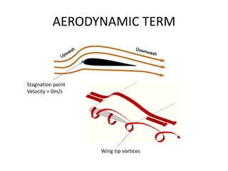
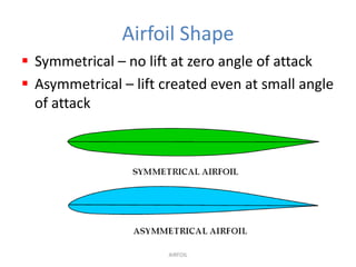
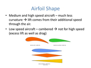
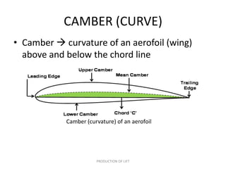
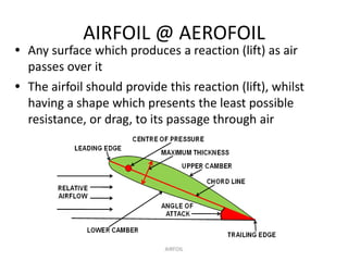
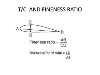
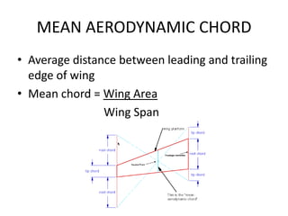
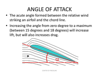
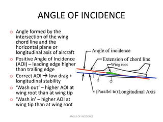
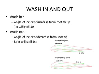
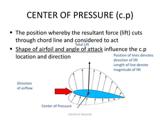
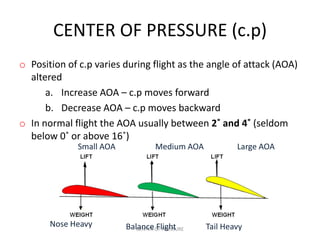
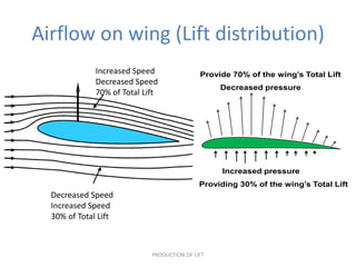
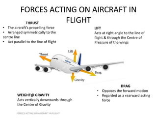
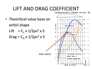
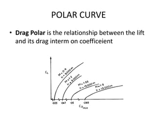
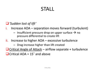
8.2 AERODYNAMICS


        www.part66.blogspot.com
Effect of Shapes on Streamlined Flow


   (a) Flat Plate 100% Resistance                 (b) Sphere 50% Resistance


   (c) Ovoid 15% Resistance                       (d) Streamlined 5% Resistance


                                    STREAMLINED
Boundary Layer


          Unaffected airflow


          Each layer experience retardation until
          some distance away from surface

           Next layer slowed down but not stop

          Airflow nearest the surface come to rest


     STREAMLINED
Boundary Layer


     STREAMLINED
Separation and turbulence at various
                AOA


                STALLING
AERODYNAMIC TERM


Stagnation point
Velocity = 0m/s


                   Wing tip vortices
Airfoil Shape
 Symmetrical – no lift at zero angle of attack
 Asymmetrical – lift created even at small angle
  of attack


                       AIRFOIL
Airfoil Shape
• Medium and high speed aircraft – much less
  curvature  lift comes from their additional speed
  through the air.
• Low speed aircraft – cambered  not for high speed
  (excess lift as well as drag)


                        AIRFOIL
CAMBER (CURVE)
• Camber  curvature of an aerofoil (wing)
  above and below the chord line


            Camber (curvature) of an aerofoil


                       PRODUCTION OF LIFT
AIRFOIL @ AEROFOIL
• Any surface which produces a reaction (lift) as air
  passes over it
• The airfoil should provide this reaction (lift), whilst
  having a shape which presents the least possible
  resistance, or drag, to its passage through air


                             AIRFOIL
T/C AND FINENESS RATIO


   Thicness/Chord ratio = CD
                          AB
MEAN AERODYNAMIC CHORD
• Average distance between leading and trailing
  edge of wing
• Mean chord = Wing Area
                Wing Span
ANGLE OF ATTACK
• The acute angle formed between the relative wind
  striking an airfoil and the chord line.
• Increasing the angle from zero degree to a maximum
  (between 15 degrees and 18 degrees) will increase
  lift, but will also increases drag.


                     CENTER OF PRESSURE
ANGLE OF INCIDENCE
o Angle formed by the
  intersection of the wing
  chord line and the
  horizontal plane or
  longitudinal axis of aircraft
o Positive Angle of Incidence
  (AOI) – leading edge higher
  than trailing edge
o Correct AOI  low drag +
  longitudinal stability
o ‘Wash out’ – higher AOI at
  wing root than at wing tip
o ‘Wash in’ – higher AOI at
  wing tip than at wing root

                            ANGLE OF INCIDENCE
WASH IN AND OUT
• Wash in :
   – Angle of incident increase from root to tip
   – Tip will stall 1st
• Wash out :
   – Angle of incident decrease from root tip
   – Root will stall 1st
CENTER OF PRESSURE (c.p)
 The position whereby the resultant force (lift) cuts
  through chord line and considered to act
                          Total Lift
 Shape of airfoil and angle of attack influence the c.p
                                           Position of lines denotes
  location and direction                   direction of lift
                                                    Length of line denote
                                                    magnitude of lift


   Direction
   of airflow


                Center of Pressure

                               CENTER OF PRESSURE
CENTER OF PRESSURE (c.p)
o Position of c.p varies during flight as the angle of attack (AOA)
  altered
      a. Increase AOA – c.p moves forward
      b. Decrease AOA – c.p moves backward
o In normal flight the AOA usually between 2˚ and 4˚ (seldom
  below 0˚ or above 16˚)
              Small AOA            Medium AOA           Large AOA


       Nose Heavy         Balance OF PRESSURE
                             CENTER Flight      Tail Heavy
WING SHAPE
ASPECT RATIO
• Ratio of aircraft wingspan to its mean chord
  length
PRODUCTION OF LIFT
 To keep flying  aircraft must
   produce a force equal to its
   own weight
 Greater force – to lift the
   aircraft from the ground
 Force (lift) is provided by the
   wing
 The production of lift is based
   on Bernoulli’s theory


                                PRODUCTION OF LIFT
Lift


Weight
Bernoulli’s theorem

• Air velocity increase – the pressure decreases (and vice
  versa)
• The total energy of a moving fluid is made up of three
  forms of energy:
    Potential Energy – due to height or position
    Kinetic Energy – due to motion
    Pressure Energy – due to pressure
• In a streamline flow of an ideal fluid, the sum of all those
  energy is constant

   Potential + Kinetic + Pressure = Constant

                            PRODUCTION OF LIFT
Venturi Effect
• A short circular tube with
  large opening at both the
  front and rear end +
  restrictor between the
  opening
• Venturi is a
  convergent/divergent
  duct
• Bernoulli’s Theory is
  being proven by passing
  a streamline flow of air
  through a venturi duct

                       PRODUCTION OF LIFT
Venturi Effect


   PRODUCTION OF LIFT
Venturi Effect
    INLET         CENTRE (THROAT)               OUTLET
Airspeed normal   Airspeed maximum         Airspeed decrease
Pressure normal   Pressure minimum         Pressure increase
                                           (equal to inlet area)


                      PRODUCTION OF LIFT
Camber (Curved)
• Airflow around the cambered wing behave exactly as airflow
                       in a venturi tube


                        PRODUCTION OF LIFT
Airflow on wing (Lift distribution)
              Increased Speed                Provide 70% of the wing’s Total Lift
              Decreased Speed
                                                  Decreased pressure
              70% of Total Lift


                                                  Increased pressure
                                             Providing 30% of the wing’s Total Lift
  Decreased Speed
  Increased Speed
  30% of Total Lift


                             PRODUCTION OF LIFT
STREAMLINED
 Streamline – shape or contour that presents a
  minimum resistance to the air
 A perfect streamlined form is similar to the top view
  of a fish
 Air flows around non-streamlined object  air swirls
  into eddies + streamline distorted  disappear
 Airstream becomes turbulent
 Streamline air appears as smooth parallel lines

• Smoke jets – introduce smoke into air  to observe
    and illustrate movement of air around object

                        STREAMLINED
Effect of Shapes on Streamlined Flow


               STREAMLINED
DRAG

As an aircraft passes through the air, the air offers
 a resistance to the passage.
This resistance, is known as ‘Drag’.
      (Resistance to forward motion)
The total amount of drag on an aircraft is made
 up of many types of drag forces.
      • Common type of drag:-
        i. Form drag
        ii. Parasite drag
        iii. Induced drag

                                DRAG
DRAG
RESISTANCE TO FORWARD MOTION


             DRAG
FORM DRAG
Caused by the shape or form of the aircraft
• Reducing form drag
• Streamlining – aircraft shaped to produce least
  resistance to the airflow
• For least resistance  object length between 3-4
  times greater than maximum thickness
• Fineness ratio – ratio between length and maximum
  thickness


                        DRAG
PARASITE DRAG
 A combination of many different drag forces
 Any exposed object on an aircraft offers some
  resistance to the airflow, and the more objects in
  the airstream, the more parasite drag
Reducing parasite drag
• reducing the number of exposed parts to as few as
  practical and streamlining their shape.


                         DRAG
Streamlining


• Fixed landing gear
SKIN FRICTION DRAG
A type of parasite drag most difficult to reduce
Air particles in contact with surface of the aircraft
Reducing skin friction
glossy flat finishes
eliminating protruding rivet heads, roughness, and other
  irregularities.


                              DRAG
INDUCED AND TOTAL DRAG
• Lift created by the airfoil also created drag 
  induced drag

• Just as lift increases with an increase in angle of
  attack, induced drag also increases as the angle of
  attack becomes greater.
                                   TOTAL DRAG


                           DRAG
THRUST AND WEIGHT
• Thrust is forward force produce by engine
• Determine by size and type use in propulsion
  system
• Weight is a mass of aircraft act vertically
  downward
• Determined by size and material used in
  aircraft
FORCES ACTING ON AIRCRAFT IN
             THRUST    FLIGHT
• The aircraft’s propelling force              LIFT
• Arranged symmetrically to the                Acts at right angle to the line of
centre line                                    flight & through the Centre of
• Act parallel to the line of flight           Pressure of the wings


                                                             DRAG
                                                • Opposes the forward motion
         WEIGHT@ GRAVITY                        • Regarded as a rearward acting
         Acts vertically downwards through        force
         the Centre of Gravity

         FORCES ACTING ON AIRCRAFT IN FLIGHT
LIFT AND DRAG COEFFICIENT
• Theoritical value base on
  airfoil shape
  Lift = CL x 1/2ρv2 x S
  Drag = CD x 1/2ρv2 x S


                    IDEAL ANGLE
POLAR CURVE
• Drag Polar is the relationship between the lift
  and its drag interm on coefficeient
STALL

 ‘Sudden lost of lift’
i. Increase AOA – separation moves forward (turbulent)
     – Insufficient pressure drop on upper surface  no
       pressure differential to create lift
ii. Increase to higher AOA – excessive turbulence
     – Drag increase higher than lift created
 Critical Angle of Attack – airflow separate + turbulence
 Critical AOA = 15˚ and above


                             STALLING
AIRFOIL CONTAMINATION
• Any contamination on wing will affect its
  performance
• Need to provide method to remove the
  contamination during flying
• Type of contamination :
  – Ice
  – Snow
  – Frost

EASA PART-66 MODULE 8.2 : AERODYNAMICS

  • 1.
    8.2 AERODYNAMICS www.part66.blogspot.com
  • 2.
    Effect of Shapeson Streamlined Flow (a) Flat Plate 100% Resistance (b) Sphere 50% Resistance (c) Ovoid 15% Resistance (d) Streamlined 5% Resistance STREAMLINED
  • 3.
    Boundary Layer Unaffected airflow Each layer experience retardation until some distance away from surface Next layer slowed down but not stop Airflow nearest the surface come to rest STREAMLINED
  • 4.
    Boundary Layer STREAMLINED
  • 5.
    Separation and turbulenceat various AOA STALLING
  • 6.
  • 7.
    Airfoil Shape  Symmetrical– no lift at zero angle of attack  Asymmetrical – lift created even at small angle of attack AIRFOIL
  • 8.
    Airfoil Shape • Mediumand high speed aircraft – much less curvature  lift comes from their additional speed through the air. • Low speed aircraft – cambered  not for high speed (excess lift as well as drag) AIRFOIL
  • 9.
    CAMBER (CURVE) • Camber curvature of an aerofoil (wing) above and below the chord line Camber (curvature) of an aerofoil PRODUCTION OF LIFT
  • 10.
    AIRFOIL @ AEROFOIL •Any surface which produces a reaction (lift) as air passes over it • The airfoil should provide this reaction (lift), whilst having a shape which presents the least possible resistance, or drag, to its passage through air AIRFOIL
  • 11.
    T/C AND FINENESSRATIO Thicness/Chord ratio = CD AB
  • 12.
    MEAN AERODYNAMIC CHORD •Average distance between leading and trailing edge of wing • Mean chord = Wing Area Wing Span
  • 13.
    ANGLE OF ATTACK •The acute angle formed between the relative wind striking an airfoil and the chord line. • Increasing the angle from zero degree to a maximum (between 15 degrees and 18 degrees) will increase lift, but will also increases drag. CENTER OF PRESSURE
  • 14.
    ANGLE OF INCIDENCE oAngle formed by the intersection of the wing chord line and the horizontal plane or longitudinal axis of aircraft o Positive Angle of Incidence (AOI) – leading edge higher than trailing edge o Correct AOI  low drag + longitudinal stability o ‘Wash out’ – higher AOI at wing root than at wing tip o ‘Wash in’ – higher AOI at wing tip than at wing root ANGLE OF INCIDENCE
  • 15.
    WASH IN ANDOUT • Wash in : – Angle of incident increase from root to tip – Tip will stall 1st • Wash out : – Angle of incident decrease from root tip – Root will stall 1st
  • 16.
    CENTER OF PRESSURE(c.p)  The position whereby the resultant force (lift) cuts through chord line and considered to act Total Lift  Shape of airfoil and angle of attack influence the c.p Position of lines denotes location and direction direction of lift Length of line denote magnitude of lift Direction of airflow Center of Pressure CENTER OF PRESSURE
  • 17.
    CENTER OF PRESSURE(c.p) o Position of c.p varies during flight as the angle of attack (AOA) altered a. Increase AOA – c.p moves forward b. Decrease AOA – c.p moves backward o In normal flight the AOA usually between 2˚ and 4˚ (seldom below 0˚ or above 16˚) Small AOA Medium AOA Large AOA Nose Heavy Balance OF PRESSURE CENTER Flight Tail Heavy
  • 18.
  • 19.
    ASPECT RATIO • Ratioof aircraft wingspan to its mean chord length
  • 20.
    PRODUCTION OF LIFT To keep flying  aircraft must produce a force equal to its own weight  Greater force – to lift the aircraft from the ground  Force (lift) is provided by the wing  The production of lift is based on Bernoulli’s theory PRODUCTION OF LIFT
  • 21.
  • 22.
    Bernoulli’s theorem • Airvelocity increase – the pressure decreases (and vice versa) • The total energy of a moving fluid is made up of three forms of energy:  Potential Energy – due to height or position  Kinetic Energy – due to motion  Pressure Energy – due to pressure • In a streamline flow of an ideal fluid, the sum of all those energy is constant Potential + Kinetic + Pressure = Constant PRODUCTION OF LIFT
  • 23.
    Venturi Effect • Ashort circular tube with large opening at both the front and rear end + restrictor between the opening • Venturi is a convergent/divergent duct • Bernoulli’s Theory is being proven by passing a streamline flow of air through a venturi duct PRODUCTION OF LIFT
  • 24.
    Venturi Effect PRODUCTION OF LIFT
  • 25.
    Venturi Effect INLET CENTRE (THROAT) OUTLET Airspeed normal Airspeed maximum Airspeed decrease Pressure normal Pressure minimum Pressure increase (equal to inlet area) PRODUCTION OF LIFT
  • 26.
    Camber (Curved) • Airflowaround the cambered wing behave exactly as airflow in a venturi tube PRODUCTION OF LIFT
  • 27.
    Airflow on wing(Lift distribution) Increased Speed Provide 70% of the wing’s Total Lift Decreased Speed Decreased pressure 70% of Total Lift Increased pressure Providing 30% of the wing’s Total Lift Decreased Speed Increased Speed 30% of Total Lift PRODUCTION OF LIFT
  • 28.
    STREAMLINED  Streamline –shape or contour that presents a minimum resistance to the air  A perfect streamlined form is similar to the top view of a fish  Air flows around non-streamlined object  air swirls into eddies + streamline distorted  disappear  Airstream becomes turbulent  Streamline air appears as smooth parallel lines • Smoke jets – introduce smoke into air  to observe and illustrate movement of air around object STREAMLINED
  • 29.
    Effect of Shapeson Streamlined Flow STREAMLINED
  • 30.
    DRAG As an aircraftpasses through the air, the air offers a resistance to the passage. This resistance, is known as ‘Drag’. (Resistance to forward motion) The total amount of drag on an aircraft is made up of many types of drag forces. • Common type of drag:- i. Form drag ii. Parasite drag iii. Induced drag DRAG
  • 31.
  • 32.
    FORM DRAG Caused bythe shape or form of the aircraft • Reducing form drag • Streamlining – aircraft shaped to produce least resistance to the airflow • For least resistance  object length between 3-4 times greater than maximum thickness • Fineness ratio – ratio between length and maximum thickness DRAG
  • 33.
    PARASITE DRAG  Acombination of many different drag forces  Any exposed object on an aircraft offers some resistance to the airflow, and the more objects in the airstream, the more parasite drag Reducing parasite drag • reducing the number of exposed parts to as few as practical and streamlining their shape. DRAG
  • 35.
  • 36.
    SKIN FRICTION DRAG Atype of parasite drag most difficult to reduce Air particles in contact with surface of the aircraft Reducing skin friction glossy flat finishes eliminating protruding rivet heads, roughness, and other irregularities. DRAG
  • 37.
    INDUCED AND TOTALDRAG • Lift created by the airfoil also created drag  induced drag • Just as lift increases with an increase in angle of attack, induced drag also increases as the angle of attack becomes greater. TOTAL DRAG DRAG
  • 38.
    THRUST AND WEIGHT •Thrust is forward force produce by engine • Determine by size and type use in propulsion system • Weight is a mass of aircraft act vertically downward • Determined by size and material used in aircraft
  • 39.
    FORCES ACTING ONAIRCRAFT IN THRUST FLIGHT • The aircraft’s propelling force LIFT • Arranged symmetrically to the Acts at right angle to the line of centre line flight & through the Centre of • Act parallel to the line of flight Pressure of the wings DRAG • Opposes the forward motion WEIGHT@ GRAVITY • Regarded as a rearward acting Acts vertically downwards through force the Centre of Gravity FORCES ACTING ON AIRCRAFT IN FLIGHT
  • 40.
    LIFT AND DRAGCOEFFICIENT • Theoritical value base on airfoil shape Lift = CL x 1/2ρv2 x S Drag = CD x 1/2ρv2 x S IDEAL ANGLE
  • 41.
    POLAR CURVE • DragPolar is the relationship between the lift and its drag interm on coefficeient
  • 42.
    STALL  ‘Sudden lostof lift’ i. Increase AOA – separation moves forward (turbulent) – Insufficient pressure drop on upper surface  no pressure differential to create lift ii. Increase to higher AOA – excessive turbulence – Drag increase higher than lift created  Critical Angle of Attack – airflow separate + turbulence  Critical AOA = 15˚ and above STALLING
  • 43.
    AIRFOIL CONTAMINATION • Anycontamination on wing will affect its performance • Need to provide method to remove the contamination during flying • Type of contamination : – Ice – Snow – Frost