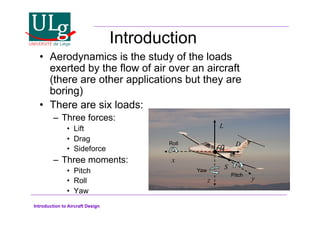
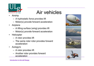
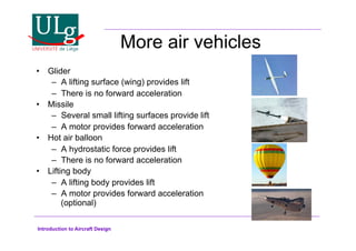
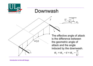
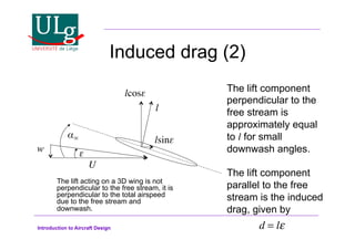
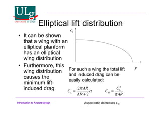
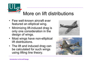
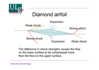
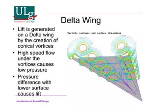
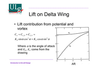
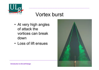
Introduction to Aircraft Design
Aircraft Design
Lecture 2:
Aerodynamics
G. Dimitriadis
Introduction to Aircraft Design
Introduction
•! Aerodynamics is the study of the loads
exerted by the flow of air over an aircraft
(there are other applications but they are
boring)
•! There are six loads:
–! Three forces:
•! Lift
•! Drag
•! Sideforce
–! Three moments:
•! Pitch
•! Roll
•! Yaw
x
z y
cg
L
D
S
Roll
Yaw
Pitch
Introduction to Aircraft Design
Why study aerodynamics?
•! Anything can fly, as long as you
put a big enough rocket engine
under it. But:
–! Thats the most expensive and
dangerous solution
–! There are still stability, control and
other problems that can only be
resolved through a good aerodynamic
study
–! There are several much better
solutions. A few of them are listed in
the next couple of slides. They all
require a good understanding of
aerodynamics.
Introduction to Aircraft Design
Air vehicles
•! Airship
–! A hydrostatic force provides lift
–! Motor(s) provide forward acceleration
•! Airplane
–! A lifting surface (wing) provides lift
–! Motor(s) provide forward acceleration
•! Helicopter
–! A rotor provides lift
–! The same rotor rotor provides forward
acceleration
•! Autogyro
–! A rotor provides lift
–! Another rotor provides forward
acceleration
Introduction to Aircraft Design
More air vehicles
•! Glider
–! A lifting surface (wing) provides lift
–! There is no forward acceleration
•! Missile
–! Several small lifting surfaces provide lift
–! A motor provides forward acceleration
•! Hot air balloon
–! A hydrostatic force provides lift
–! There is no forward acceleration
•! Lifting body
–! A lifting body provides lift
–! A motor provides forward acceleration
(optional)
Introduction to Aircraft Design
Airplane
•! In this course we will mostly talk about
airplanes
•! The most popular airplane configuration is
wing+fuselage+tail
•! The configuration mirrors birds. The Wright
brothers and others before them were
inspired by bird flight
•! Each component has a distinct role:
–! The wing provides lift
–! The fuselage holds cargo, passengers etc
–! The tail provides stability and control
Introduction to Aircraft Design
Wings
•! The role of the wing is to generate lift
•! Lift creation can be described in two ways:
–! Pressure differential: The air pressure on the
bottom surface of the wing is higher than the air
pressure of the top surface. This pressure
difference creates a net force upwards
–! Newtons third law: The wing pushes air
downwards. As a consequence, the air itself
pushes the wing upwards.
–! Either way, the laws of conservation apply: mass,
momentum and energy.
Introduction to Aircraft Design
Lift generation
•! Lift generation of wings depends on
their cross-sectional shape
•! The Wright brothers were the first to
study the effects of different cross
sectional shape
•! They determined that the airfoil is the
optimum cross-sectional shape for a
wing
Introduction to Aircraft Design
Airfoils
•! Flow visualization
Pulsed jets show that
the flow moves faster
over the top surface.
By Bernoulis principle,
faster flow speeds mean
lower pressure
Hence the pressure
differential causing lift
Introduction to Aircraft Design
Airfoils continued
•! But why is the flow
accelerated on the
top surface?
•! Because it must
separate at the
trailing edge.
•! Therefore, aircraft
can fly because of
viscosity
U
!
U
!
!
c
U=airspeed
!=angle of attack
c=chord
!=circulation
Introduction to Aircraft Design
Shape effect (camber)
Camber increases the
amount of lift produced
by the airfoil
Symmetric airfoil - no lift at 0o aoa Cambered airfoil - produces lift at 0o aoa
Introduction to Aircraft Design
Pressure distribution
•! The static pressure around a lifting airfoil looks
something like:
T.E. Stagnation point
L.E. Stagnation point
Minimum pressure point
The lift is the integral
of the pressure
difference over the
chord:
l = pl x
( )! pu x
( )
( )
0
c
 dx
cp =
p ! pref
1/2U2
Pressure coefficient
p=pressure
pref=reference pressure
=air density
l=lift
Introduction to Aircraft Design
Lift
•! The amount of lift produced by an airfoil is
also proportional to the total circulation
required for the flow to separate at the trailing
edge
•! Where  is the air density, U the free stream
airspeed and ! the circulation.
•! For flat plates and small angles of attack this
result simplifies to
l = !U
l = !U2
#
Introduction to Aircraft Design
Lift coefficient
•! A lift coefficient is a non-dimensional
quantity defined as
•! For a flat plate, the lift coefficient can be
obtained from
cl =
l
1
2
!U2
c
cl = 2!
Introduction to Aircraft Design
True lift
As shown in the video
earlier the flow cannot
remain attached to the
wings surface at high
angles of attack.
Flow separation results in
loss of lift. Important
characteristics:
•!Maximum lift coefficient
•!Maximum lift angle of
attack
Introduction to Aircraft Design
Pitching moment
•! The lift is a single force but it is caused by a continuous
pressure distribution.
•! Therefore, it must have a point of application. This point is
called the Centre of Pressure (cp).
•! The moment caused by the lift acting at the cp around the
leading edge is called the pitching moment.
•! Pitching moment coefficient:
xcp!
l!
U!
cm =
m
1
2
!U2
c2
m!
Introduction to Aircraft Design
Drag
Unfortunately, all bodies in a
real airflow are subjected to
a drag force.
There are no easy
expressions for the
calculation of drag. There are
many sources of drag and
few of them are easily
modeled.
Drag: d
Drag coefficient:
cd =
d
1
2
!U2
c
Introduction to Aircraft Design
The boundary layer
•! Drag in two dimensions cannot be modeled at
all using inviscid assumptions
•! Prandtl was the first to realize that viscous
effects are very important in a thin layer of
flow near the wings surface
•! Skin friction and momentum deficit within the
boundary layer are some of the major
sources of drag
Introduction to Aircraft Design
Momentum deficit
•! Momentum deficit can be visualized as:
•! The flow in front of the airfoil and just
after it looks like:
•! In other words, momentum has been
lost. Loss of momentum = drag force.
Introduction to Aircraft Design
Graphical representation
Boundary layer
Flow accelerates
Flow decelerates
High
pressure
Low
pressure High
pressure
Very high
pressure
Very low
pressure
Very high
pressure
Separation
Introduction to Aircraft Design
Stall
Introduction to Aircraft Design
Coordinate system
•! The values of lift and drag also depend on the
coordinate system we choose.
•! The most consistent definition of lift and drag is:
–! Lift is a force perpendicular to the free stream.
–! Drag is a force parallel to the free stream.
•! Therefore, the integral of the pressure
distribution around the airfoil is not the lift but
the force acting normal to the surface:
•! So that the actual lift is l=ncos. In general, if
the normal, n, and tangential, n, forces are
known:
n = pl x
( )! pu x
( )
( )
0
c
 dx
l = ncos!  tsin!
d = tcos! + nsin!
n!
t!
d!
l!
Introduction to Aircraft Design
Airfoil characteristics
•! Chord length, (c)
•! Thickness, (t)
•! Camber, (dz/dx)
•! Shape (e.g.
NACA 0012)
•! Lift curve slope (cl!)
•! Zero-lift angle (cl0)
•! Maximum lift angle
(!clmax)
•! Maximum lift coefficient
(clmax)
•! Minimum drag coefficient
(cdmin)
Design Parameters Performance Parameters
Introduction to Aircraft Design
NACA 4-digit Airfoils
•! These airfoils were developed in the
20s and 30s based on earlier Göttingen
and Clark Y sections
•! They use a very specific terminology
Introduction to Aircraft Design
NACA 4-digit airfoils
•! Defined by
•! Where yupper=yt+yc, ylower=-yt+yc, yt is the thickness
shape and yc is the camber shape, xcmax is the chord-
wise position of maximum camber, t is the maximum
thickness and cmax is the maximum camber.
±yt =
t / c
0.2
0.2969 x ! 0.1260x ! 0.3516x2
+ 0.2843x3
! 0.1015x4
( )
yc =
cmax / c
p2
2xcmax
x ! x2
( ) from x = 0 to x = xcmax
yc =
cmax / c
1! p
( )2 1! 2xcmax
( )+ 2xcmax
x ! x2
( ) from x = xcmax
to x = c
Introduction to Aircraft Design
Wings
•! A wing can be seen
as an extrusion of
an airfoil in the y-
direction.
x z
y
s
Wing span: b
Wing half-span: s=b/2
Wing area over full
span: S
Aspect ratio: AR=b2/S
Introduction to Aircraft Design
Forces on wings
•! In principle, it is simple to calculate the
aerodynamic lift acting on a wing: it is
simply the integral of the sectional lift
over the span:
•! Unfortunately, the sectional lift variation
is not easy to calculate
L = l(y)dy
!s
s
 , or, CL = cl (y)dy
!s
s
 , where CL =
L
1/ 2#U2
S
Introduction to Aircraft Design
2D vs 3D force coefficients
•! 2D lift, drag, moment etc. coefficients:
–! Use lowercase letters: cl, cd, cm, etc.
–! Use chord or chord2 to normalize, e.g.
•! 3D lift, drag, moment etc. coefficients:
–! Use uppercase letters: CL, CD, CM, etc.
–! Use surface area or surface*chord to
normalize, e.g.
cd =
d
1
2
!U2
c
, cm =
m
1
2
!U2
c2
CD =
D
1
2
!U2
S
, CM =
M
1
2
!U2
Sc
Introduction to Aircraft Design
Lifting line theory
The wing is modeled
mathematically by a
single horseshoe-
shaped vortex (black
line)
Flow visualization
showing that the
horse-shoe vortex is
a good approximation
of real flow
The stronger the vortex,
the higher the lift
Wingtip or
trailing vortices
Bound vortex
Introduction to Aircraft Design
Wingtip vortex visualization
•! Tip vortices
of large
aircraft can
cause
serious
problems in
airports.
Introduction to Aircraft Design
Induced drag
•! Three-dimensional wings feature one very
clear and simple to quantify source of drag:
induced drag.
•! In essence, the fact that a wing produces lift
means that it also produces drag.
•! The drag is proportional to the square of the
lift.
•! The source of induced drag is a downwash
flow velocity created on the wing by the
trailing vortices.
Introduction to Aircraft Design
Downwash
w(y)!
y!
The effective angle of attack
is the difference between
the geometric angle of
attack and the angle
induced by the downwash.
#! e!
U!
!e = ! #$ = ! #
w
U
Introduction to Aircraft Design
Induced drag (2)
U!
!
w! $!
l!
lcos$!
lsin$!
The lift component
perpendicular to the
free stream is
approximately equal
to l for small
downwash angles.
The lift component
parallel to the free
stream is the induced
drag, given by
d = l!
The lift acting on a 3D wing is not
perpendicular to the free stream, it is
perpendicular to the total airspeed
due to the free stream and
downwash.
Introduction to Aircraft Design
Elliptical lift distribution
•! It can be shown
that a wing with an
elliptical planform
has an elliptical
wing distribution
•! Furthermore, this
wing distribution
causes the
minimum lift-
induced drag
y
cl
For such a wing the total lift
and induced drag can be
easily calculated:
CL =
2!AR
AR + 2
 CD =
CL
2
!AR
Aspect ratio decreases CD
Introduction to Aircraft Design
More on lift distributions
•! Few well-known aircraft ever
featured an elliptical wing.
•! Minimizing lift-induced drag is
only one consideration in the
design of wings.
•! Most wings have non-elliptical
lift distributions.
•! The lift and induced drag can
be calculated for such wings
using lifting line theory.
Introduction to Aircraft Design
Sources of drag
•! Parasite drag:
–!Skin friction drag (friction)
–!Form drag (also known as pressure or profile
drag)
–!Interference drag (vortices created at the
intersection of surfaces)
•! Induced drag (due to downwash of wings)
•! Wave drag (supersonic drag)
Introduction to Aircraft Design
Wing characteristics
•! Aspect Ratio
•! Twist: angle of attack at root is not the same
as angle of attack at tip
•! Taper: chord at tip is smaller than chord at
root
•! Thickness ratio: Wing thickness varies over
the span
•! Airfoil: may change over wingspan
•! Sweep: wingtip lies behind or in front of wing
root
Introduction to Aircraft Design
Aspect Ratio
Low aspect ratio wing
F-15
High aspect ratio wing
B-52
Introduction to Aircraft Design
Aspect Ratio
•! The Aspect Ratio is one of the basic
design parameters for transport aircraft.
•! It has a significant effect on aircraft
performance. This will be discussed at a
later lecture.
•! Large values of AR tend to make the flow
around the wind more 2D.
•! Remember that 2D flows do not cause
induced drag.
•! Therefore, a very high aspect ratio
increases the lift coefficient and decreases
the drag coefficient.
Introduction to Aircraft Design
Twisted wings
Introduction to Aircraft Design
Wing twist
•! Wash-in: !tip  !root
•! Wash-out: !tip  !root
y
cl
Wash-out
Wash-in
No twist
The effect of twist is
usually modeled by
defining the basic lift
distribution (no twist)
and the additional lift
distribution (lift due only
to twist)
Wings often have wash-
out to reduce structural
weight and improve stall
characteristics
Introduction to Aircraft Design
More on wing twist
•! The point of initial stalling should be
sufficiently inboard, around 0.4s from the wing
root.
•! This can be achieved with suitable twist. If the
stall point is too far outboard, a little washout
will bring it inboard.
•! However, a washout of more than 5o results
in an unacceptable increase in induced drag.
Introduction to Aircraft Design
Tapered Wings
•! Most World War II fighter aircraft had
tapered wings
Introduction to Aircraft Design
Wing taper
•! The taper ratio is defined as
•! Taper reduces the amount of lift produced
near the wing-tip.
•! Consequently, the tip vortex is weaker and
the induced drag is decreased.
•! Taper also reduces structural weight
•! As the chord at the root is unchanged the
maximum lift is not severely affected by taper
•! If the taper is not too high, the stalling
characteristics are acceptable, even without
twist
! = ctip / croot
Introduction to Aircraft Design
Effect of wing taper on lift
distribution
y
cl
#=0
#=0.2
#=0.5
#=1.0
Taper
increases
sectional lift
coefficient!
Introduction to Aircraft Design
Non-linear taper
•! Taper doesnt have to be linear
P-51 Mustang
Cessna 150
Introduction to Aircraft Design
No taper
•! Untapered wings are easy and cheap to
manufacture but aerodynamically
inferior to tapered wings
Cessna 140
Cessna 120
Introduction to Aircraft Design
Thickness-to-chord ratio
•! High Aspect Ratio is good for transport
aircraft: it decreases the induced drag
coefficient.
•! For such wings to be structurally sound, they
must be very thick near the root.
•! This is usually achieved by increasing the
thickness ratio near the wing
•! Thickness affects also the profile drag. Too
much increase in thickness can cancel the
decrease in induced drag due to high AR.
Introduction to Aircraft Design
Thickness-to-chord ratio
•! Thickness ratio also affects
the maximum lift
•! Optimal thickness ratios:
–! 15-20% near the wing root
–! 10-15% near the wing tip
•! Higher than 20% is not
good
Maximum CL for NACA
airfoils
Introduction to Aircraft Design
Airfoil selection
•! The airfoil section does not affect the
wing lift distribution at small angles of
attack
•! It affects mainly:
–!The curve of local clmax
–!The profile drag
y
cl
0.4s
clmax(y)
cl(y)
Introduction to Aircraft Design
Airfoil choices
•! NACA four-digit airfoils:
–! Drag increase with lift is gradual
–! Cambered sections have good maximum lift and
docile stall
–! Gradual changes in drag and pitching moment
–! They are used in light aircraft (mostly wingtips and
tailplanes) and trainers (gradual changes are good
for training aircraft).
•! NACA five-digit
–! Better maximum lift than 4-digit but very abrupt
stall
–! They are sometimes used inboard, combined with
4-digit airfoils near the wingtip.
Introduction to Aircraft Design
More airfoils
•! NACA 6-series
–!Also known as laminar flow series
–!Designed to have low profile drag at low lift
coefficients - the low drag bucket region
–!They also have high critical Mach numbers
–!Lower maximum lift than 4- and 5-digit
series
–!Extensively tested and very well
documented
Introduction to Aircraft Design
Airfoil selection considerations
•! In short, airfoil selection should be
made using the following
considerations:
–!An airfoil with low profile drag at the design
flight conditions must be chosen
–!The airfoil must be capable of giving the
desired maximum lift to the wing (with flaps
if needed)
–!Compressibility issues must be addressed
Introduction to Aircraft Design
Compressibility issues
•! High subsonic cruise Mach numbers
can be attained by:
–!Using sweepback
–!Reducing the thickness-to-chord ratio
–!Using improved airfoil sections
(supercritical airfoils)
–!Optimizing spanwise camber and twist
variation
Introduction to Aircraft Design
Zero sweep angle
•! BAe ATP:
Maximum
airspeed of 137m/
s at 25000ft, i.e.
maximum M=0.44
•! Straight tapered
wings
Introduction to Aircraft Design
High sweep angle
•! Airbus A380:
Maximum airspeed
of 265m/s at 35000ft,
i.e. maximum
M=0.89
•! Highly swept tapered
wings
Introduction to Aircraft Design
Types of sweep
Straight quarter-line chord
Reduced sweep at inboard
section
Increased sweep at inboard
section
$
c/4
Introduction to Aircraft Design
Effect of sweep
V
VT
VN
A component of the free stream
airspeed, VT is tangent to the
wing. Therefore, the airspeed
seen by the airfoil is only VN
VN=Vcos$
The effective Mach number
seen by the wings airfoil is
Meff=Mcos$%
A higher V is required to
achieve the sonic conditions
Introduction to Aircraft Design
Using sweepback
•! Up to M=0.65 or M=0.7, straight wings
with appropriate thickness ratio are
sufficient.
•! At higher Mach numbers, sweepback is
required
•! A sweep angle of 35 degrees is rarely
exceeded
Introduction to Aircraft Design
Sweep data
Aircraft Aspect Ratio Taper Ratio Sweep Angle Maximum
Mach
VFW-Fokker
614
7.22 0.402 15o
0.65
Yakovlev Yak
40
9.00 0.396 0o
0.70
Fokker-VFW F
28
7.27 0.355 16o
0.75
BAC 1-11
200/400
8.00 0.321 20o
0.78
Aerospatialle
Caravelle
8.02 0.354 20o
0.81
Boeing 737
100/200
8.83 0.251 25o
0.84
MDD DC-8
10/50/60
7.30 0.244 30o
0.88
Boeing 707 7.11 0.293 35o
0.90
Boeing 747 6.96 0.309 37o
30’ 0.92
It is clear that
sweep angle
increases with
Mach number.
Taper ratio also,
generally,
increases with
Mach number.
Introduction to Aircraft Design
Shock waves
•! Shock waves can be formed on the
upper (and even lower) surfaces of
wings travelling in transonic (i.e. M1)
flow. For example:
Introduction to Aircraft Design
Airfoils for
Transonic
Conditions
Introduction to Aircraft Design
Transonic airfoils
•! Rooftop: They have a relatively flat pressure
distribution on the forward upper surface. The
flow is not accelerated in this region and the
advent of M=1 is delayed. NACA 6-series
•! Peaky upper surface: Supersonic velocities
and suction near the leading edge, followed
by a weak shock wave. The drag rise is
postponed to higher airspeeds. BAC 1-11,
VC-10 and DC-9 have used this.
Introduction to Aircraft Design
Transonic airfoils
•! Supercritical airfoils: They have a flat upper
surface, creating shock-free supersonic flow
region. This region is much greater than that
of the peaky distribution
•! Rear loading: The rear lower surface is highly
cambered so that a lot of lift is generated near
the rear of the airfoil. When combined with a
flat upper surface (supercritical airfoil) a large
decrease in drag for the same Mach number
and lift coefficient can be obtained.
•! This combination has been used by Airbus
A300 and all subsequent civil transports
Introduction to Aircraft Design
Design thickness ratio
•! A value for the most appropriate thickness
ratio for a particular Mach number can be
obtained from
•! Where M*=1 for conventional airfoils, M*=1.05
for peaky airfoils and M*=1.15 for supercritical
airfoils
•! Mcos% can be used for sweptback wings
t / c = 0.3 1!
5 + M 2
5 + M*2

#
$
%

'
3.5
(
)
*
*
+
,
-
-
1! M 2
M 2
.
/
0
1
0
2
3
0
4
0
2/3
Introduction to Aircraft Design
Wing lift coefficient
(unswept wings)
•! The lift wing coefficient can be
estimated by
CL = CL!
!
CL!
= 0.995
cl!
E + cl!
/ AR
E = 1+
2#
AR 1+ #
( )
CL!=wing lift curve slope
cl!=sectional lift curve slope
E=Jones correction
#=taper ratio
AR=Aspect ratio
Introduction to Aircraft Design
Wing lift coefficient
(unswept wings)
•! For a sectional lift curve slope of 2
•! Compressibility effects can be taken
into account by replacing AR by 'AR
and CL! by 'CL!, where
CL!
=
2
1+
2
AR
1+ 2#
1+ #
! = 1 M 2
Introduction to Aircraft Design
Wing lift coefficient
(swept wings)
•! For swept wings, an approximate
expression for the wing lift curve slope
is
•! $1/2 is the sweepback angle at the half-
chord
!CL
=
2#
2
!AR
+
1
k2
cos2
$!
+
2
!A
%

'
(
)
*
2
where tan$! =
tan$1/2
!
and k =
!cl
2#
Introduction to Aircraft Design
Wing maximum lift coefficient
•! The maximum lift coefficient of a wing
can be approximated by
•! Where ks=0.88 for untapered wings and
ks=0.95 for tapered wings.
CLmax
= ks
clmax,root
+ clmax,tip
2
Introduction to Aircraft Design
Wing-fuselage interference
The fuselage
produces very
little (if any) lift.
However, some
lift is carried
over from the
wing onto the
fuselage.
Introduction to Aircraft Design
Supersonic flight
•! Supersonic flight requires different wing
design because:
–!Lift generation mechanisms are different
–!Much more drag is produced
•! Supersonic airfoils are usually very thin
and sharp
•! Supersonic wings are either trapezoidal
or Delta-shaped
Introduction to Aircraft Design
Trapezoidal wings
Bell X-1
F-104 F-22?
Introduction to Aircraft Design
Delta Wings
Concorde
MiG-21 Mirage 2000
Introduction to Aircraft Design
Supersonic flow over flat plate
Expansion waves
Shock wave
(compression)
pu is lower than pl so that there is a net force
upwards - lift
Introduction to Aircraft Design
Lift on supersonic flat plate
•! It is easy to calculate the lift on a flat plate
airfoil in a supersonic flow
•! The compression and expansion cause
pressure coefficients of
•! The force acting normal to the plate is
•! Leading to a lift coefficient of:
cpl
=
2!
M 2
1
cpu
= !
2
M 2
!1
cl = cn cos! =
4!
M 2
1
cn =
1
c
cpdx =
1
c
(cpl
!
0
c

!
 cpu
)dx =
4#
M 2
!1
Introduction to Aircraft Design
Drag on supersonic flat plate
•! Unlike incompressible flow, supersonic
flow causes drag, known as wave drag.
•! The drag force is obtained from the
normal force as
cd = cn sin! =
4!2
M 2
1
Introduction to Aircraft Design
Diamond airfoil
Weak shock
Expansion
Strong shock
Strong shock
Expansion Weak shock
The difference in shock strengths causes the flow
on the lower surface to be compressed more
than the flow on the upper surface.
Introduction to Aircraft Design
Delta Wing
•! Lift is generated
on a Delta wing
by the creation of
conical vortices
•! High speed flow
under the
vortices causes
low pressure
•! Pressure
difference with
lower surface
causes lift
Introduction to Aircraft Design
Lift on Delta Wing
•! Lift contribution from potential and
vortex
CL = CL,P + CL,V =
KP sin! cos2
! + KV cos! sin2
!
AR
Where ! is the angle of attack
and KP, KV come from the
drawing
Introduction to Aircraft Design
Vortex burst
•! At very high angles
of attack the
vortices can break
down
•! Loss of lift ensues
Introduction to Aircraft Design
Delta Wings at low speeds
•! Delta wings are quite inefficient at low speeds
•! Concorde had to fly at an uncomfortably high
angle of attack to take off and land
•! Several solutions have been tried
–! Canards
–! Compound Delta
–! Swing-wing
–! Leading Edge Extensions
Introduction to Aircraft Design
Canards
•! This was the solution adopted by the
Tu-144
The canards
were there
specifically to
control the
aircraft at low
airspeeds
Introduction to Aircraft Design
Compound Delta
Two Delta wings
superimposed, with
different sweeps. The
highly swept section
creates additional, stronger
vortices that increase lift
and serve to keep the flow
attached at higher angles of
attack
Saab-35 Draken
F-16XL
Introduction to Aircraft Design
Swing-Wing
•! Quite a simple concept: at high speeds
you get a Delta, at low speeds you get a
high AR trapezoidal wing
F-14
Introduction to Aircraft Design
Leading Edge Extensions
•! Some aircraft combine
the advantages of Delta
wings with those of
trapezoidal wings
•! Leading Edge
Extensions (as on this
F-18) create vortices just
as Delta Wings
•! The vortices can keep
the flow over the wing
attached at very high
angles of attack

02 - Conception D Aero Aerodynamisme.pdf

  • 1.
    Introduction to AircraftDesign Aircraft Design Lecture 2: Aerodynamics G. Dimitriadis
  • 2.
    Introduction to AircraftDesign Introduction •! Aerodynamics is the study of the loads exerted by the flow of air over an aircraft (there are other applications but they are boring) •! There are six loads: –! Three forces: •! Lift •! Drag •! Sideforce –! Three moments: •! Pitch •! Roll •! Yaw x z y cg L D S Roll Yaw Pitch
  • 3.
    Introduction to AircraftDesign Why study aerodynamics? •! Anything can fly, as long as you put a big enough rocket engine under it. But: –! Thats the most expensive and dangerous solution –! There are still stability, control and other problems that can only be resolved through a good aerodynamic study –! There are several much better solutions. A few of them are listed in the next couple of slides. They all require a good understanding of aerodynamics.
  • 4.
    Introduction to AircraftDesign Air vehicles •! Airship –! A hydrostatic force provides lift –! Motor(s) provide forward acceleration •! Airplane –! A lifting surface (wing) provides lift –! Motor(s) provide forward acceleration •! Helicopter –! A rotor provides lift –! The same rotor rotor provides forward acceleration •! Autogyro –! A rotor provides lift –! Another rotor provides forward acceleration
  • 5.
    Introduction to AircraftDesign More air vehicles •! Glider –! A lifting surface (wing) provides lift –! There is no forward acceleration •! Missile –! Several small lifting surfaces provide lift –! A motor provides forward acceleration •! Hot air balloon –! A hydrostatic force provides lift –! There is no forward acceleration •! Lifting body –! A lifting body provides lift –! A motor provides forward acceleration (optional)
  • 6.
    Introduction to AircraftDesign Airplane •! In this course we will mostly talk about airplanes •! The most popular airplane configuration is wing+fuselage+tail •! The configuration mirrors birds. The Wright brothers and others before them were inspired by bird flight •! Each component has a distinct role: –! The wing provides lift –! The fuselage holds cargo, passengers etc –! The tail provides stability and control
  • 7.
    Introduction to AircraftDesign Wings •! The role of the wing is to generate lift •! Lift creation can be described in two ways: –! Pressure differential: The air pressure on the bottom surface of the wing is higher than the air pressure of the top surface. This pressure difference creates a net force upwards –! Newtons third law: The wing pushes air downwards. As a consequence, the air itself pushes the wing upwards. –! Either way, the laws of conservation apply: mass, momentum and energy.
  • 8.
    Introduction to AircraftDesign Lift generation •! Lift generation of wings depends on their cross-sectional shape •! The Wright brothers were the first to study the effects of different cross sectional shape •! They determined that the airfoil is the optimum cross-sectional shape for a wing
  • 9.
    Introduction to AircraftDesign Airfoils •! Flow visualization Pulsed jets show that the flow moves faster over the top surface. By Bernoulis principle, faster flow speeds mean lower pressure Hence the pressure differential causing lift
  • 10.
    Introduction to AircraftDesign Airfoils continued •! But why is the flow accelerated on the top surface? •! Because it must separate at the trailing edge. •! Therefore, aircraft can fly because of viscosity U ! U ! ! c U=airspeed !=angle of attack c=chord !=circulation
  • 11.
    Introduction to AircraftDesign Shape effect (camber) Camber increases the amount of lift produced by the airfoil Symmetric airfoil - no lift at 0o aoa Cambered airfoil - produces lift at 0o aoa
  • 12.
    Introduction to AircraftDesign Pressure distribution •! The static pressure around a lifting airfoil looks something like: T.E. Stagnation point L.E. Stagnation point Minimum pressure point The lift is the integral of the pressure difference over the chord: l = pl x ( )! pu x ( ) ( ) 0 c dx cp = p ! pref 1/2U2 Pressure coefficient p=pressure pref=reference pressure =air density l=lift
  • 13.
    Introduction to AircraftDesign Lift •! The amount of lift produced by an airfoil is also proportional to the total circulation required for the flow to separate at the trailing edge •! Where is the air density, U the free stream airspeed and ! the circulation. •! For flat plates and small angles of attack this result simplifies to l = !U l = !U2 #
  • 14.
    Introduction to AircraftDesign Lift coefficient •! A lift coefficient is a non-dimensional quantity defined as •! For a flat plate, the lift coefficient can be obtained from cl = l 1 2 !U2 c cl = 2!
  • 15.
    Introduction to AircraftDesign True lift As shown in the video earlier the flow cannot remain attached to the wings surface at high angles of attack. Flow separation results in loss of lift. Important characteristics: •!Maximum lift coefficient •!Maximum lift angle of attack
  • 16.
    Introduction to AircraftDesign Pitching moment •! The lift is a single force but it is caused by a continuous pressure distribution. •! Therefore, it must have a point of application. This point is called the Centre of Pressure (cp). •! The moment caused by the lift acting at the cp around the leading edge is called the pitching moment. •! Pitching moment coefficient: xcp! l! U! cm = m 1 2 !U2 c2 m!
  • 17.
    Introduction to AircraftDesign Drag Unfortunately, all bodies in a real airflow are subjected to a drag force. There are no easy expressions for the calculation of drag. There are many sources of drag and few of them are easily modeled. Drag: d Drag coefficient: cd = d 1 2 !U2 c
  • 18.
    Introduction to AircraftDesign The boundary layer •! Drag in two dimensions cannot be modeled at all using inviscid assumptions •! Prandtl was the first to realize that viscous effects are very important in a thin layer of flow near the wings surface •! Skin friction and momentum deficit within the boundary layer are some of the major sources of drag
  • 19.
    Introduction to AircraftDesign Momentum deficit •! Momentum deficit can be visualized as: •! The flow in front of the airfoil and just after it looks like: •! In other words, momentum has been lost. Loss of momentum = drag force.
  • 20.
    Introduction to AircraftDesign Graphical representation Boundary layer Flow accelerates Flow decelerates High pressure Low pressure High pressure Very high pressure Very low pressure Very high pressure Separation
  • 21.
  • 22.
    Introduction to AircraftDesign Coordinate system •! The values of lift and drag also depend on the coordinate system we choose. •! The most consistent definition of lift and drag is: –! Lift is a force perpendicular to the free stream. –! Drag is a force parallel to the free stream. •! Therefore, the integral of the pressure distribution around the airfoil is not the lift but the force acting normal to the surface: •! So that the actual lift is l=ncos. In general, if the normal, n, and tangential, n, forces are known: n = pl x ( )! pu x ( ) ( ) 0 c dx l = ncos! tsin! d = tcos! + nsin! n! t! d! l!
  • 23.
    Introduction to AircraftDesign Airfoil characteristics •! Chord length, (c) •! Thickness, (t) •! Camber, (dz/dx) •! Shape (e.g. NACA 0012) •! Lift curve slope (cl!) •! Zero-lift angle (cl0) •! Maximum lift angle (!clmax) •! Maximum lift coefficient (clmax) •! Minimum drag coefficient (cdmin) Design Parameters Performance Parameters
  • 24.
    Introduction to AircraftDesign NACA 4-digit Airfoils •! These airfoils were developed in the 20s and 30s based on earlier Göttingen and Clark Y sections •! They use a very specific terminology
  • 25.
    Introduction to AircraftDesign NACA 4-digit airfoils •! Defined by •! Where yupper=yt+yc, ylower=-yt+yc, yt is the thickness shape and yc is the camber shape, xcmax is the chord- wise position of maximum camber, t is the maximum thickness and cmax is the maximum camber. ±yt = t / c 0.2 0.2969 x ! 0.1260x ! 0.3516x2 + 0.2843x3 ! 0.1015x4 ( ) yc = cmax / c p2 2xcmax x ! x2 ( ) from x = 0 to x = xcmax yc = cmax / c 1! p ( )2 1! 2xcmax ( )+ 2xcmax x ! x2 ( ) from x = xcmax to x = c
  • 26.
    Introduction to AircraftDesign Wings •! A wing can be seen as an extrusion of an airfoil in the y- direction. x z y s Wing span: b Wing half-span: s=b/2 Wing area over full span: S Aspect ratio: AR=b2/S
  • 27.
    Introduction to AircraftDesign Forces on wings •! In principle, it is simple to calculate the aerodynamic lift acting on a wing: it is simply the integral of the sectional lift over the span: •! Unfortunately, the sectional lift variation is not easy to calculate L = l(y)dy !s s , or, CL = cl (y)dy !s s , where CL = L 1/ 2#U2 S
  • 28.
    Introduction to AircraftDesign 2D vs 3D force coefficients •! 2D lift, drag, moment etc. coefficients: –! Use lowercase letters: cl, cd, cm, etc. –! Use chord or chord2 to normalize, e.g. •! 3D lift, drag, moment etc. coefficients: –! Use uppercase letters: CL, CD, CM, etc. –! Use surface area or surface*chord to normalize, e.g. cd = d 1 2 !U2 c , cm = m 1 2 !U2 c2 CD = D 1 2 !U2 S , CM = M 1 2 !U2 Sc
  • 29.
    Introduction to AircraftDesign Lifting line theory The wing is modeled mathematically by a single horseshoe- shaped vortex (black line) Flow visualization showing that the horse-shoe vortex is a good approximation of real flow The stronger the vortex, the higher the lift Wingtip or trailing vortices Bound vortex
  • 30.
    Introduction to AircraftDesign Wingtip vortex visualization •! Tip vortices of large aircraft can cause serious problems in airports.
  • 31.
    Introduction to AircraftDesign Induced drag •! Three-dimensional wings feature one very clear and simple to quantify source of drag: induced drag. •! In essence, the fact that a wing produces lift means that it also produces drag. •! The drag is proportional to the square of the lift. •! The source of induced drag is a downwash flow velocity created on the wing by the trailing vortices.
  • 32.
    Introduction to AircraftDesign Downwash w(y)! y! The effective angle of attack is the difference between the geometric angle of attack and the angle induced by the downwash. #! e! U! !e = ! #$ = ! # w U
  • 33.
    Introduction to AircraftDesign Induced drag (2) U! ! w! $! l! lcos$! lsin$! The lift component perpendicular to the free stream is approximately equal to l for small downwash angles. The lift component parallel to the free stream is the induced drag, given by d = l! The lift acting on a 3D wing is not perpendicular to the free stream, it is perpendicular to the total airspeed due to the free stream and downwash.
  • 34.
    Introduction to AircraftDesign Elliptical lift distribution •! It can be shown that a wing with an elliptical planform has an elliptical wing distribution •! Furthermore, this wing distribution causes the minimum lift- induced drag y cl For such a wing the total lift and induced drag can be easily calculated: CL = 2!AR AR + 2 CD = CL 2 !AR Aspect ratio decreases CD
  • 35.
    Introduction to AircraftDesign More on lift distributions •! Few well-known aircraft ever featured an elliptical wing. •! Minimizing lift-induced drag is only one consideration in the design of wings. •! Most wings have non-elliptical lift distributions. •! The lift and induced drag can be calculated for such wings using lifting line theory.
  • 36.
    Introduction to AircraftDesign Sources of drag •! Parasite drag: –!Skin friction drag (friction) –!Form drag (also known as pressure or profile drag) –!Interference drag (vortices created at the intersection of surfaces) •! Induced drag (due to downwash of wings) •! Wave drag (supersonic drag)
  • 37.
    Introduction to AircraftDesign Wing characteristics •! Aspect Ratio •! Twist: angle of attack at root is not the same as angle of attack at tip •! Taper: chord at tip is smaller than chord at root •! Thickness ratio: Wing thickness varies over the span •! Airfoil: may change over wingspan •! Sweep: wingtip lies behind or in front of wing root
  • 38.
    Introduction to AircraftDesign Aspect Ratio Low aspect ratio wing F-15 High aspect ratio wing B-52
  • 39.
    Introduction to AircraftDesign Aspect Ratio •! The Aspect Ratio is one of the basic design parameters for transport aircraft. •! It has a significant effect on aircraft performance. This will be discussed at a later lecture. •! Large values of AR tend to make the flow around the wind more 2D. •! Remember that 2D flows do not cause induced drag. •! Therefore, a very high aspect ratio increases the lift coefficient and decreases the drag coefficient.
  • 40.
    Introduction to AircraftDesign Twisted wings
  • 41.
    Introduction to AircraftDesign Wing twist •! Wash-in: !tip !root •! Wash-out: !tip !root y cl Wash-out Wash-in No twist The effect of twist is usually modeled by defining the basic lift distribution (no twist) and the additional lift distribution (lift due only to twist) Wings often have wash- out to reduce structural weight and improve stall characteristics
  • 42.
    Introduction to AircraftDesign More on wing twist •! The point of initial stalling should be sufficiently inboard, around 0.4s from the wing root. •! This can be achieved with suitable twist. If the stall point is too far outboard, a little washout will bring it inboard. •! However, a washout of more than 5o results in an unacceptable increase in induced drag.
  • 43.
    Introduction to AircraftDesign Tapered Wings •! Most World War II fighter aircraft had tapered wings
  • 44.
    Introduction to AircraftDesign Wing taper •! The taper ratio is defined as •! Taper reduces the amount of lift produced near the wing-tip. •! Consequently, the tip vortex is weaker and the induced drag is decreased. •! Taper also reduces structural weight •! As the chord at the root is unchanged the maximum lift is not severely affected by taper •! If the taper is not too high, the stalling characteristics are acceptable, even without twist ! = ctip / croot
  • 45.
    Introduction to AircraftDesign Effect of wing taper on lift distribution y cl #=0 #=0.2 #=0.5 #=1.0 Taper increases sectional lift coefficient!
  • 46.
    Introduction to AircraftDesign Non-linear taper •! Taper doesnt have to be linear P-51 Mustang Cessna 150
  • 47.
    Introduction to AircraftDesign No taper •! Untapered wings are easy and cheap to manufacture but aerodynamically inferior to tapered wings Cessna 140 Cessna 120
  • 48.
    Introduction to AircraftDesign Thickness-to-chord ratio •! High Aspect Ratio is good for transport aircraft: it decreases the induced drag coefficient. •! For such wings to be structurally sound, they must be very thick near the root. •! This is usually achieved by increasing the thickness ratio near the wing •! Thickness affects also the profile drag. Too much increase in thickness can cancel the decrease in induced drag due to high AR.
  • 49.
    Introduction to AircraftDesign Thickness-to-chord ratio •! Thickness ratio also affects the maximum lift •! Optimal thickness ratios: –! 15-20% near the wing root –! 10-15% near the wing tip •! Higher than 20% is not good Maximum CL for NACA airfoils
  • 50.
    Introduction to AircraftDesign Airfoil selection •! The airfoil section does not affect the wing lift distribution at small angles of attack •! It affects mainly: –!The curve of local clmax –!The profile drag y cl 0.4s clmax(y) cl(y)
  • 51.
    Introduction to AircraftDesign Airfoil choices •! NACA four-digit airfoils: –! Drag increase with lift is gradual –! Cambered sections have good maximum lift and docile stall –! Gradual changes in drag and pitching moment –! They are used in light aircraft (mostly wingtips and tailplanes) and trainers (gradual changes are good for training aircraft). •! NACA five-digit –! Better maximum lift than 4-digit but very abrupt stall –! They are sometimes used inboard, combined with 4-digit airfoils near the wingtip.
  • 52.
    Introduction to AircraftDesign More airfoils •! NACA 6-series –!Also known as laminar flow series –!Designed to have low profile drag at low lift coefficients - the low drag bucket region –!They also have high critical Mach numbers –!Lower maximum lift than 4- and 5-digit series –!Extensively tested and very well documented
  • 53.
    Introduction to AircraftDesign Airfoil selection considerations •! In short, airfoil selection should be made using the following considerations: –!An airfoil with low profile drag at the design flight conditions must be chosen –!The airfoil must be capable of giving the desired maximum lift to the wing (with flaps if needed) –!Compressibility issues must be addressed
  • 54.
    Introduction to AircraftDesign Compressibility issues •! High subsonic cruise Mach numbers can be attained by: –!Using sweepback –!Reducing the thickness-to-chord ratio –!Using improved airfoil sections (supercritical airfoils) –!Optimizing spanwise camber and twist variation
  • 55.
    Introduction to AircraftDesign Zero sweep angle •! BAe ATP: Maximum airspeed of 137m/ s at 25000ft, i.e. maximum M=0.44 •! Straight tapered wings
  • 56.
    Introduction to AircraftDesign High sweep angle •! Airbus A380: Maximum airspeed of 265m/s at 35000ft, i.e. maximum M=0.89 •! Highly swept tapered wings
  • 57.
    Introduction to AircraftDesign Types of sweep Straight quarter-line chord Reduced sweep at inboard section Increased sweep at inboard section $ c/4
  • 58.
    Introduction to AircraftDesign Effect of sweep V VT VN A component of the free stream airspeed, VT is tangent to the wing. Therefore, the airspeed seen by the airfoil is only VN VN=Vcos$ The effective Mach number seen by the wings airfoil is Meff=Mcos$% A higher V is required to achieve the sonic conditions
  • 59.
    Introduction to AircraftDesign Using sweepback •! Up to M=0.65 or M=0.7, straight wings with appropriate thickness ratio are sufficient. •! At higher Mach numbers, sweepback is required •! A sweep angle of 35 degrees is rarely exceeded
  • 60.
    Introduction to AircraftDesign Sweep data Aircraft Aspect Ratio Taper Ratio Sweep Angle Maximum Mach VFW-Fokker 614 7.22 0.402 15o 0.65 Yakovlev Yak 40 9.00 0.396 0o 0.70 Fokker-VFW F 28 7.27 0.355 16o 0.75 BAC 1-11 200/400 8.00 0.321 20o 0.78 Aerospatialle Caravelle 8.02 0.354 20o 0.81 Boeing 737 100/200 8.83 0.251 25o 0.84 MDD DC-8 10/50/60 7.30 0.244 30o 0.88 Boeing 707 7.11 0.293 35o 0.90 Boeing 747 6.96 0.309 37o 30’ 0.92 It is clear that sweep angle increases with Mach number. Taper ratio also, generally, increases with Mach number.
  • 61.
    Introduction to AircraftDesign Shock waves •! Shock waves can be formed on the upper (and even lower) surfaces of wings travelling in transonic (i.e. M1) flow. For example:
  • 62.
    Introduction to AircraftDesign Airfoils for Transonic Conditions
  • 63.
    Introduction to AircraftDesign Transonic airfoils •! Rooftop: They have a relatively flat pressure distribution on the forward upper surface. The flow is not accelerated in this region and the advent of M=1 is delayed. NACA 6-series •! Peaky upper surface: Supersonic velocities and suction near the leading edge, followed by a weak shock wave. The drag rise is postponed to higher airspeeds. BAC 1-11, VC-10 and DC-9 have used this.
  • 64.
    Introduction to AircraftDesign Transonic airfoils •! Supercritical airfoils: They have a flat upper surface, creating shock-free supersonic flow region. This region is much greater than that of the peaky distribution •! Rear loading: The rear lower surface is highly cambered so that a lot of lift is generated near the rear of the airfoil. When combined with a flat upper surface (supercritical airfoil) a large decrease in drag for the same Mach number and lift coefficient can be obtained. •! This combination has been used by Airbus A300 and all subsequent civil transports
  • 65.
    Introduction to AircraftDesign Design thickness ratio •! A value for the most appropriate thickness ratio for a particular Mach number can be obtained from •! Where M*=1 for conventional airfoils, M*=1.05 for peaky airfoils and M*=1.15 for supercritical airfoils •! Mcos% can be used for sweptback wings t / c = 0.3 1! 5 + M 2 5 + M*2 # $ % ' 3.5 ( ) * * + , - - 1! M 2 M 2 . / 0 1 0 2 3 0 4 0 2/3
  • 66.
    Introduction to AircraftDesign Wing lift coefficient (unswept wings) •! The lift wing coefficient can be estimated by CL = CL! ! CL! = 0.995 cl! E + cl! / AR E = 1+ 2# AR 1+ # ( ) CL!=wing lift curve slope cl!=sectional lift curve slope E=Jones correction #=taper ratio AR=Aspect ratio
  • 67.
    Introduction to AircraftDesign Wing lift coefficient (unswept wings) •! For a sectional lift curve slope of 2 •! Compressibility effects can be taken into account by replacing AR by 'AR and CL! by 'CL!, where CL! = 2 1+ 2 AR 1+ 2# 1+ # ! = 1 M 2
  • 68.
    Introduction to AircraftDesign Wing lift coefficient (swept wings) •! For swept wings, an approximate expression for the wing lift curve slope is •! $1/2 is the sweepback angle at the half- chord !CL = 2# 2 !AR + 1 k2 cos2 $! + 2 !A % ' ( ) * 2 where tan$! = tan$1/2 ! and k = !cl 2#
  • 69.
    Introduction to AircraftDesign Wing maximum lift coefficient •! The maximum lift coefficient of a wing can be approximated by •! Where ks=0.88 for untapered wings and ks=0.95 for tapered wings. CLmax = ks clmax,root + clmax,tip 2
  • 70.
    Introduction to AircraftDesign Wing-fuselage interference The fuselage produces very little (if any) lift. However, some lift is carried over from the wing onto the fuselage.
  • 71.
    Introduction to AircraftDesign Supersonic flight •! Supersonic flight requires different wing design because: –!Lift generation mechanisms are different –!Much more drag is produced •! Supersonic airfoils are usually very thin and sharp •! Supersonic wings are either trapezoidal or Delta-shaped
  • 72.
    Introduction to AircraftDesign Trapezoidal wings Bell X-1 F-104 F-22?
  • 73.
    Introduction to AircraftDesign Delta Wings Concorde MiG-21 Mirage 2000
  • 74.
    Introduction to AircraftDesign Supersonic flow over flat plate Expansion waves Shock wave (compression) pu is lower than pl so that there is a net force upwards - lift
  • 75.
    Introduction to AircraftDesign Lift on supersonic flat plate •! It is easy to calculate the lift on a flat plate airfoil in a supersonic flow •! The compression and expansion cause pressure coefficients of •! The force acting normal to the plate is •! Leading to a lift coefficient of: cpl = 2! M 2 1 cpu = ! 2 M 2 !1 cl = cn cos! = 4! M 2 1 cn = 1 c cpdx = 1 c (cpl ! 0 c ! cpu )dx = 4# M 2 !1
  • 76.
    Introduction to AircraftDesign Drag on supersonic flat plate •! Unlike incompressible flow, supersonic flow causes drag, known as wave drag. •! The drag force is obtained from the normal force as cd = cn sin! = 4!2 M 2 1
  • 77.
    Introduction to AircraftDesign Diamond airfoil Weak shock Expansion Strong shock Strong shock Expansion Weak shock The difference in shock strengths causes the flow on the lower surface to be compressed more than the flow on the upper surface.
  • 78.
    Introduction to AircraftDesign Delta Wing •! Lift is generated on a Delta wing by the creation of conical vortices •! High speed flow under the vortices causes low pressure •! Pressure difference with lower surface causes lift
  • 79.
    Introduction to AircraftDesign Lift on Delta Wing •! Lift contribution from potential and vortex CL = CL,P + CL,V = KP sin! cos2 ! + KV cos! sin2 ! AR Where ! is the angle of attack and KP, KV come from the drawing
  • 80.
    Introduction to AircraftDesign Vortex burst •! At very high angles of attack the vortices can break down •! Loss of lift ensues
  • 81.
    Introduction to AircraftDesign Delta Wings at low speeds •! Delta wings are quite inefficient at low speeds •! Concorde had to fly at an uncomfortably high angle of attack to take off and land •! Several solutions have been tried –! Canards –! Compound Delta –! Swing-wing –! Leading Edge Extensions
  • 82.
    Introduction to AircraftDesign Canards •! This was the solution adopted by the Tu-144 The canards were there specifically to control the aircraft at low airspeeds
  • 83.
    Introduction to AircraftDesign Compound Delta Two Delta wings superimposed, with different sweeps. The highly swept section creates additional, stronger vortices that increase lift and serve to keep the flow attached at higher angles of attack Saab-35 Draken F-16XL
  • 84.
    Introduction to AircraftDesign Swing-Wing •! Quite a simple concept: at high speeds you get a Delta, at low speeds you get a high AR trapezoidal wing F-14
  • 85.
    Introduction to AircraftDesign Leading Edge Extensions •! Some aircraft combine the advantages of Delta wings with those of trapezoidal wings •! Leading Edge Extensions (as on this F-18) create vortices just as Delta Wings •! The vortices can keep the flow over the wing attached at very high angles of attack