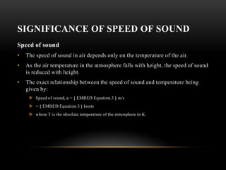
1) The document discusses the significance of the speed of sound in flight, defining subsonic, transonic, and supersonic flight based on Mach numbers.
2) It explains how air pressure and airflow behave differently depending on whether aircraft speed is below or above the speed of sound.
3) The key principles discussed include how lift is generated via pressure differences on the top and bottom surfaces of airfoils, as well as how angle of attack and airfoil shape impact lift and drag forces.

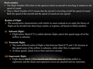


![AIRFOIL AND LIFT
• The airfoil shape and angle of attack work together so that the airfoil exerts a downward force on
the air as it flows past.
• According to Newton's third law, the air must then exert an equal and opposite (upward) force on
the airfoil, which is the lift.
• The force is exerted by the air as a pressure difference on the airfoil's surfaces
• Pressure in a fluid is always positive in an absolute sense, so that pressure must always be
thought of as pushing, and never as pulling.
• The pressure thus pushes inward on the airfoil everywhere on both the upper and lower
surfaces.
• The flowing air reacts to the presence of the wing by reducing the pressure on the wing's upper
surface and increasing the pressure on the lower surface.
• The pressure on the lower surface pushes up harder than the reduced pressure on the upper
surface pushes down, and the net result is upward lift.[54]
• The pressure difference that exerts lift acts directly on the airfoil surfaces.](https://image.slidesharecdn.com/mod2basicprinciplesofflight-230724013334-57ec1715/85/Mod2_Basic-principles-of-flight-pdf-16-320.jpg)


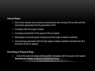


![LIFT OVER 3 D WING
For wings of moderate-to-high aspect ratio the flow at any station along the span except close
to the tips behaves much like flow around a two-dimensional airfoil,
and most explanations of lift, like those above, concentrate on two-dimensional flow. However,
even for wings of high aspect ratio,
the three-dimensional effects associated with finite span are significant across the whole span,
not just close to the tips.
The lift tends to decrease in the span wise direction from root to tip, and the pressure
distributions around the airfoil sections change accordingly in the spanwise direction.
Pressure distributions in planes perpendicular to the flight direction tend to look like the
illustration at right.
This spanwise-varying pressure distribution is sustained by a mutual interaction with the
velocity field.
Flow below the wing is accelerated outboard, flow outboard of the tips is accelerated upward,
and flow above the wing is accelerated inboard, which results in the flow pattern illustrated at
right.[95]](https://image.slidesharecdn.com/mod2basicprinciplesofflight-230724013334-57ec1715/85/Mod2_Basic-principles-of-flight-pdf-34-320.jpg)


![[Mason] transonic aerodynamics of airfoils and wings](https://cdn.slidesharecdn.com/ss_thumbnails/masontransonicaerodynamicsofairfoilsandwings-140516105801-phpapp01-thumbnail.jpg?width=640&height=640&fit=bounds)


