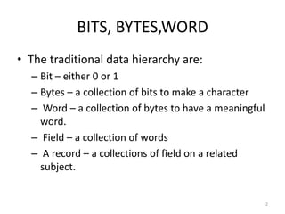
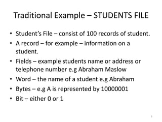
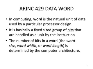
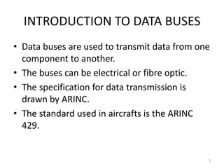
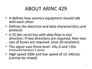
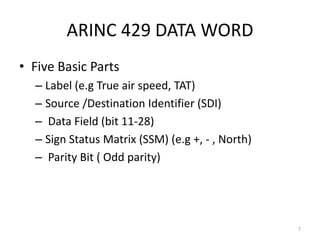
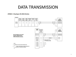
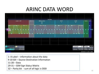
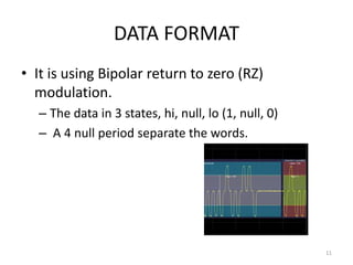
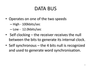
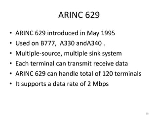
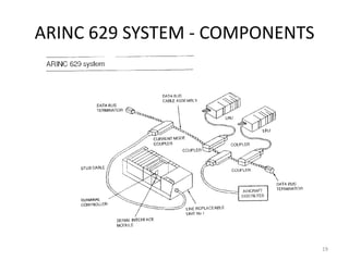
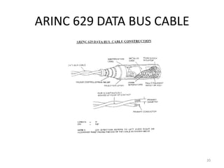
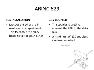
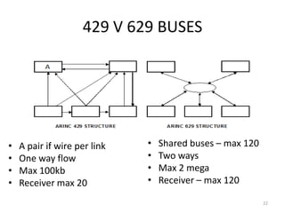
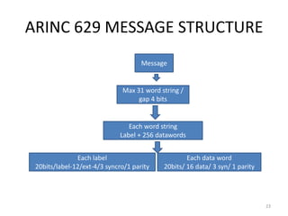
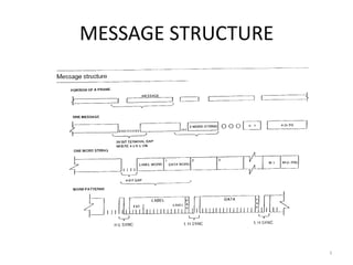
5.4 DATA BUSES


     www.part66.blogspot.com

                               1
BITS, BYTES,WORD
• The traditional data hierarchy are:
  – Bit – either 0 or 1
  – Bytes – a collection of bits to make a character
  – Word – a collection of bytes to have a meaningful
    word.
  – Field – a collection of words
  – A record – a collections of field on a related
    subject.


                                                        2
Traditional Example – STUDENTS FILE
• Student’s File – consist of 100 records of student.
• A record – for example – information on a
  student.
• Fields – example students name or address or
  telephone number e.g Abraham Maslow
• Word – the name of a student e.g Abraham
• Bytes – e.g A is represented by 10000001
• Bit – either 0 or 1

                                                        3
ARINC 429 DATA WORD
• In computing, word is the natural unit of data
  used by a particular processor design.
• It is basically a fixed sized group of bits that
  are handled as a unit by the instruction
• The number of bits in a word (the word
  size, word width, or word length) is
  determined by the computer architecture.


                                                     4
INTRODUCTION TO DATA BUSES
• Data buses are used to transmit data from one
  component to another.
• The buses can be electrical or fibre optic.
• The specification for data transmission is
  drawn by ARINC.
• The standard used in aircrafts is the ARINC
  429.


                                              5
ABOUT ARINC 429
• It defines how avionics equipment should talk
  with each other.
• Defines the electrical and data characteristics and
  protocol.
• A 32 bits serial bus with data flow in one
  direction. If two directions are required, then two
  sets of buses are required. (max 20 receivers)
• The signal uses three level -10v, 0 and +10v.
  (measured between 2 wires)
• High speed 100k and low speed of 12-14k/sec
  (cannot be mixed)
                                                    6
ARINC 429 DATA WORD
• Five Basic Parts
  – Label (e.g True air speed, TAT)
  – Source /Destination Identifier (SDI)
  – Data Field (bit 11-28)
  – Sign Status Matrix (SSM) (e.g +, - , North)
  – Parity Bit ( Odd parity)


                                                  7
8
DATA TRANSMISSION


                    9
ARINC DATA WORD


1- 8 Label – information about the data
9-10 SDI – Source Destination Information
11-28 – Data
29-31 – SSM Sign Status Matrix
32 – Parity bit - sum of all logic is ODD
                                            10
DATA FORMAT
• It is using Bipolar return to zero (RZ)
  modulation.
  – The data in 3 states, hi, null, lo (1, null, 0)
  – A 4 null period separate the words.


                                                      11
DATA BUS
• Operates on one of the two speeds
  – High - 100kbits/sec
  – Low - 12.0kbits/sec
• Self clocking – the receiver receives the null
  between the bits to generate its internal clock.
• Self synchronous – the 4 bits null is recognized
  and used to generate word synchronisation.


                                                 12
VOLTAGE LEVEL
• The voltage used is +10 , 0 and -10 volts.
• +10volts signifies logic 1 and (-10v) is logic 0
  (obsolute voltage +- 5 )
• The second half of the bit is always null.
• The shield is grounded at both end of he wire.


                                                     13
INSTALLATION


               14
1977    => Boeing began to work on “DATAC”
       project

1977 - 85 => DATAC Emerged as ARINC 629

1989    => ARINC 629 was adopted by AEEC

1990    => ARINC 629 was first implemented
       in BOEING-777

                                             15
Triple-Triple Redundant
777 Primary Flight Computer


                              16
Time Division Multiplex
Linear Bus
Multiple Transmitter Access
2 Mbps Data Rate
Current Mode Coupling
(Present implementation)


                              17
ARINC 629
•   ARINC 629 introduced in May 1995
•   Used on B777, A330 andA340 .
•   Multiple-source, multiple sink system
•   Each terminal can transmit receive data
•   ARINC 629 can handle total of 120 terminals
•   It supports a data rate of 2 Mbps


                                                  18
ARINC 629 SYSTEM - COMPONENTS


                                19
ARINC 629 DATA BUS CABLE


                           20
ARINC 629
BUS INSTALLATION                 BUS COUPLER
• Most of the wires are in       • The coupler is used to
  electronics compartment.         connect the LRU to the data
  This to enable the black         bus.
  boxes to talk to each other.   • A maximum of 120 couplers
                                   can be connected.


                                                             21
429 V 629 BUSES


•   A pair if wire per link   •   Shared buses – max 120
•   One way flow              •   Two ways
•   Max 100kb                 •   Max 2 mega
•   Receiver max 20           •   Receiver – max 120

                                                           22
ARINC 629 MESSAGE STRUCTURE
                                     Message


                              Max 31 word string /
                                   gap 4 bits


                                 Each word string
                              Label + 256 datawords


               Each label                           Each data word
 20bits/label-12/ext-4/3 syncro/1 parity    20bits/ 16 data/ 3 syn/ 1 parity


                                                                               23
MESSAGE STRUCTURE


                    24

EASA PART-66 MODULE 5.4 : DATA BUSES

  • 1.
    5.4 DATA BUSES www.part66.blogspot.com 1
  • 2.
    BITS, BYTES,WORD • Thetraditional data hierarchy are: – Bit – either 0 or 1 – Bytes – a collection of bits to make a character – Word – a collection of bytes to have a meaningful word. – Field – a collection of words – A record – a collections of field on a related subject. 2
  • 3.
    Traditional Example –STUDENTS FILE • Student’s File – consist of 100 records of student. • A record – for example – information on a student. • Fields – example students name or address or telephone number e.g Abraham Maslow • Word – the name of a student e.g Abraham • Bytes – e.g A is represented by 10000001 • Bit – either 0 or 1 3
  • 4.
    ARINC 429 DATAWORD • In computing, word is the natural unit of data used by a particular processor design. • It is basically a fixed sized group of bits that are handled as a unit by the instruction • The number of bits in a word (the word size, word width, or word length) is determined by the computer architecture. 4
  • 5.
    INTRODUCTION TO DATABUSES • Data buses are used to transmit data from one component to another. • The buses can be electrical or fibre optic. • The specification for data transmission is drawn by ARINC. • The standard used in aircrafts is the ARINC 429. 5
  • 6.
    ABOUT ARINC 429 •It defines how avionics equipment should talk with each other. • Defines the electrical and data characteristics and protocol. • A 32 bits serial bus with data flow in one direction. If two directions are required, then two sets of buses are required. (max 20 receivers) • The signal uses three level -10v, 0 and +10v. (measured between 2 wires) • High speed 100k and low speed of 12-14k/sec (cannot be mixed) 6
  • 7.
    ARINC 429 DATAWORD • Five Basic Parts – Label (e.g True air speed, TAT) – Source /Destination Identifier (SDI) – Data Field (bit 11-28) – Sign Status Matrix (SSM) (e.g +, - , North) – Parity Bit ( Odd parity) 7
  • 8.
  • 9.
  • 10.
    ARINC DATA WORD 1-8 Label – information about the data 9-10 SDI – Source Destination Information 11-28 – Data 29-31 – SSM Sign Status Matrix 32 – Parity bit - sum of all logic is ODD 10
  • 11.
    DATA FORMAT • Itis using Bipolar return to zero (RZ) modulation. – The data in 3 states, hi, null, lo (1, null, 0) – A 4 null period separate the words. 11
  • 12.
    DATA BUS • Operateson one of the two speeds – High - 100kbits/sec – Low - 12.0kbits/sec • Self clocking – the receiver receives the null between the bits to generate its internal clock. • Self synchronous – the 4 bits null is recognized and used to generate word synchronisation. 12
  • 13.
    VOLTAGE LEVEL • Thevoltage used is +10 , 0 and -10 volts. • +10volts signifies logic 1 and (-10v) is logic 0 (obsolute voltage +- 5 ) • The second half of the bit is always null. • The shield is grounded at both end of he wire. 13
  • 14.
  • 15.
    1977 => Boeing began to work on “DATAC” project 1977 - 85 => DATAC Emerged as ARINC 629 1989 => ARINC 629 was adopted by AEEC 1990 => ARINC 629 was first implemented in BOEING-777 15
  • 16.
  • 17.
    Time Division Multiplex LinearBus Multiple Transmitter Access 2 Mbps Data Rate Current Mode Coupling (Present implementation) 17
  • 18.
    ARINC 629 • ARINC 629 introduced in May 1995 • Used on B777, A330 andA340 . • Multiple-source, multiple sink system • Each terminal can transmit receive data • ARINC 629 can handle total of 120 terminals • It supports a data rate of 2 Mbps 18
  • 19.
    ARINC 629 SYSTEM- COMPONENTS 19
  • 20.
    ARINC 629 DATABUS CABLE 20
  • 21.
    ARINC 629 BUS INSTALLATION BUS COUPLER • Most of the wires are in • The coupler is used to electronics compartment. connect the LRU to the data This to enable the black bus. boxes to talk to each other. • A maximum of 120 couplers can be connected. 21
  • 22.
    429 V 629BUSES • A pair if wire per link • Shared buses – max 120 • One way flow • Two ways • Max 100kb • Max 2 mega • Receiver max 20 • Receiver – max 120 22
  • 23.
    ARINC 629 MESSAGESTRUCTURE Message Max 31 word string / gap 4 bits Each word string Label + 256 datawords Each label Each data word 20bits/label-12/ext-4/3 syncro/1 parity 20bits/ 16 data/ 3 syn/ 1 parity 23
  • 24.