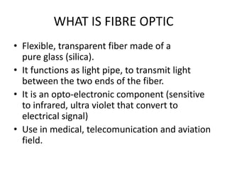
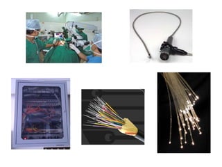
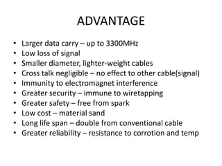
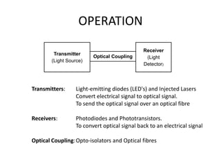
5.10 FIBRE OPTIC
WHAT IS FIBRE OPTIC
• Flexible, transparent fiber made of a
  pure glass (silica).
• It functions as light pipe, to transmit light
  between the two ends of the fiber.
• It is an opto-electronic component (sensitive
  to infrared, ultra violet that convert to
  electrical signal)
• Use in medical, telecomunication and aviation
  field.
ADVANTAGE
•   Larger data carry – up to 3300MHz
•   Low loss of signal
•   Smaller diameter, lighter-weight cables
•   Cross talk negligible – no effect to other cable(signal)
•   Immunity to electromagnet interference
•   Greater security – immune to wiretapping
•   Greater safety – free from spark
•   Low cost – material sand
•   Long life span – double from conventional cable
•   Greater reliability – resistance to corrotion and temp
DISADVANTAGE
•   Installation cost high
•   Fragile than wire
•   Required special equipment for testing
•   Required special skill and equipment to
    splicing it
OPERATION
                                               Receiver
         Transmitter
                          Optical Coupling      (Light
        (Light Source)
                                               Detector)


Transmitters:     Light-emitting diodes (LED's) and Injected Lasers
                  Convert electrical signal to optical signal.
                  To send the optical signal over an optical fibre

Receivers:         Photodiodes and Phototransistors.
                   To convert optical signal back to an electrical signal

Optical Coupling: Opto-isolators and Optical fibres
LIGHT
• Light wave more shorter than electromagnetic
  wave (radio/radar).
• Velocity 3x10⁸m/s, change depend on
  medium.
• Propogation of light :
  – Reflection
  – Refraction
  – Dispersion
REFLECTION
The light reflect back with same angle if surface is smooth


The light diffuse reflection if surface is irregular/rough
REFRACTION
Bending of light when passes through other medium


                                  Air                 1 00

                                  Diamond             2 42

                                  Ethyl Alcohol       1 36

                                  Fused Quartz        1 46

                                  Glass             1 55 - 1 9

                                  Optical Fibre        15

                                  Water               1 33

                                        Index of refraction
DISPERSION
• Seperation of white light to the various color.
• Different color have a different
  wavelength, different velocity and different
  index of refraction.
CABLE STRUCTURE
High strength and tension resistance
Typically cable made in length of 1-3 km without splices.


         Core - glass, polystyrene, polymethylmethacrylic.
         Cladding - glass, silicon or Teflon.
TYPE OF CABLE

                Wide graded index multimode
                optical fibre


             Single mode step index optical fibre


      Large-core plastic-clad silica optical fibre
HOW IT WORK
Single Mode


Multimode
ACCEPTANCE ZONE
NUMERICAL APERTURE
• Its a colecting power of an optical fibre
• Its value from 0 to 1,
• Larger NA mean the greater amount light
  accepted by fibre.
• NA is function of refractive index of the fibre.
• Define as NA = sin A
PULSE SPREADING
• The amount of acceptance signal have a limited
  frequency due to the pulse(light) is being dispers inside
  the cable.
• Dispersion tend to slow down the speed of the light.
• Two form of dispersion :
   – Chromatic disepersion : Different speed due to
                                color
   – Modal dispersion : Zigzag ray reach the end of cable
                         later than straight ray

• Total Dispersion = Chromatic + Modal
CONSEQUENCES
• The fastest the pulse travel, the worse
  spreading its get.
• Need to limit the frequency of the signal travel
ATTENUATION
• Reduction of signal strength due to :
   1. Atomic Absorption :
        Atom of material absorb some of the light
   2. Scatering by Flaw and Impurities :
        Depend on size of scatering particle
        inside the cable
   3. Reflection by Splices and Conector :
        Some light are reflected back even for perfect
        splice or conector.
JOINING OPTICAL FIBRE
– Fusion Splicing
   • Allign manually using micromanipulators and
     microscope system.
   • End of fibre are melt together using electric arc.
   • Near perfect splice can lose as low 0.2dB

– Mechanical Splicing
   • Two fibre end held together in splice equipment which
     automatically allign the two fibre.
   • Clamp it and expose to ultra-violet light to cures the
     cement
SPLICING ERROR
• The end of fibre must be precisely line each
  other to enable light pass from one fibre to
  another.
• Typicall allignment error :
FIBRE OPTIC CONNECTOR
2 Type Conector A and B, both have :
- Allignment key and grooves
- Guide pin and cavities
- Color bands
- Three start threads
                                       A type :
                                       - 3 or 5 optical fibre
                                       - Multichannel
                                       - very low loss


                                       B type :
                                       - For LRU
                                       - Multichannel
                                       - For more frequent
                                         conection and disconection
FIBRE OPTIC IN AIRCRAFT
• Advantage on aircraft :
  – Can carry more data
  – Less weight
  – Immune to electromagnetic radiation
• Purpose:
  – Network system: (OLAN),(AVLAN),(CABLAN)
AIRCRAFT NETWORK SYSTEM
• Flight attendent
   –   Keep sales data
   –   Enable and disable passenger functions
   –   Control the distribution of video entertainment
   –   Select boarding music
• Passenger
   –   Video and menu screen
   –   Games
   –   Inflight sales catalogue
   –   Instruction for telephone call
   –   Ground to airplane telephone pages
   –   Special video channel selection
ONBOARD LAN
CABIN LAN

EASA Part 66 Module 5.10 : Fibre Optic

  • 1.
  • 2.
    WHAT IS FIBREOPTIC • Flexible, transparent fiber made of a pure glass (silica). • It functions as light pipe, to transmit light between the two ends of the fiber. • It is an opto-electronic component (sensitive to infrared, ultra violet that convert to electrical signal) • Use in medical, telecomunication and aviation field.
  • 4.
    ADVANTAGE • Larger data carry – up to 3300MHz • Low loss of signal • Smaller diameter, lighter-weight cables • Cross talk negligible – no effect to other cable(signal) • Immunity to electromagnet interference • Greater security – immune to wiretapping • Greater safety – free from spark • Low cost – material sand • Long life span – double from conventional cable • Greater reliability – resistance to corrotion and temp
  • 5.
    DISADVANTAGE • Installation cost high • Fragile than wire • Required special equipment for testing • Required special skill and equipment to splicing it
  • 6.
    OPERATION Receiver Transmitter Optical Coupling (Light (Light Source) Detector) Transmitters: Light-emitting diodes (LED's) and Injected Lasers Convert electrical signal to optical signal. To send the optical signal over an optical fibre Receivers: Photodiodes and Phototransistors. To convert optical signal back to an electrical signal Optical Coupling: Opto-isolators and Optical fibres
  • 7.
    LIGHT • Light wavemore shorter than electromagnetic wave (radio/radar). • Velocity 3x10⁸m/s, change depend on medium. • Propogation of light : – Reflection – Refraction – Dispersion
  • 8.
    REFLECTION The light reflectback with same angle if surface is smooth The light diffuse reflection if surface is irregular/rough
  • 9.
    REFRACTION Bending of lightwhen passes through other medium Air 1 00 Diamond 2 42 Ethyl Alcohol 1 36 Fused Quartz 1 46 Glass 1 55 - 1 9 Optical Fibre 15 Water 1 33 Index of refraction
  • 10.
    DISPERSION • Seperation ofwhite light to the various color. • Different color have a different wavelength, different velocity and different index of refraction.
  • 11.
    CABLE STRUCTURE High strengthand tension resistance Typically cable made in length of 1-3 km without splices. Core - glass, polystyrene, polymethylmethacrylic. Cladding - glass, silicon or Teflon.
  • 12.
    TYPE OF CABLE Wide graded index multimode optical fibre Single mode step index optical fibre Large-core plastic-clad silica optical fibre
  • 13.
    HOW IT WORK SingleMode Multimode
  • 14.
  • 15.
    NUMERICAL APERTURE • Itsa colecting power of an optical fibre • Its value from 0 to 1, • Larger NA mean the greater amount light accepted by fibre. • NA is function of refractive index of the fibre. • Define as NA = sin A
  • 16.
    PULSE SPREADING • Theamount of acceptance signal have a limited frequency due to the pulse(light) is being dispers inside the cable. • Dispersion tend to slow down the speed of the light. • Two form of dispersion : – Chromatic disepersion : Different speed due to color – Modal dispersion : Zigzag ray reach the end of cable later than straight ray • Total Dispersion = Chromatic + Modal
  • 17.
    CONSEQUENCES • The fastestthe pulse travel, the worse spreading its get. • Need to limit the frequency of the signal travel
  • 18.
    ATTENUATION • Reduction ofsignal strength due to : 1. Atomic Absorption : Atom of material absorb some of the light 2. Scatering by Flaw and Impurities : Depend on size of scatering particle inside the cable 3. Reflection by Splices and Conector : Some light are reflected back even for perfect splice or conector.
  • 19.
    JOINING OPTICAL FIBRE –Fusion Splicing • Allign manually using micromanipulators and microscope system. • End of fibre are melt together using electric arc. • Near perfect splice can lose as low 0.2dB – Mechanical Splicing • Two fibre end held together in splice equipment which automatically allign the two fibre. • Clamp it and expose to ultra-violet light to cures the cement
  • 20.
    SPLICING ERROR • Theend of fibre must be precisely line each other to enable light pass from one fibre to another. • Typicall allignment error :
  • 21.
    FIBRE OPTIC CONNECTOR 2Type Conector A and B, both have : - Allignment key and grooves - Guide pin and cavities - Color bands - Three start threads A type : - 3 or 5 optical fibre - Multichannel - very low loss B type : - For LRU - Multichannel - For more frequent conection and disconection
  • 22.
    FIBRE OPTIC INAIRCRAFT • Advantage on aircraft : – Can carry more data – Less weight – Immune to electromagnetic radiation • Purpose: – Network system: (OLAN),(AVLAN),(CABLAN)
  • 23.
    AIRCRAFT NETWORK SYSTEM •Flight attendent – Keep sales data – Enable and disable passenger functions – Control the distribution of video entertainment – Select boarding music • Passenger – Video and menu screen – Games – Inflight sales catalogue – Instruction for telephone call – Ground to airplane telephone pages – Special video channel selection
  • 24.
  • 25.