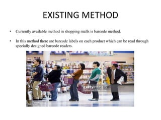
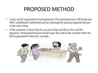
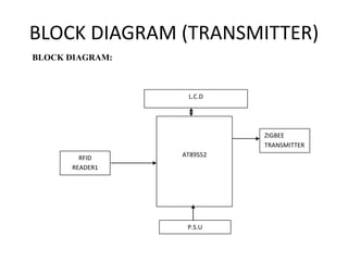
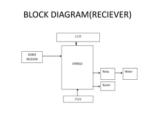
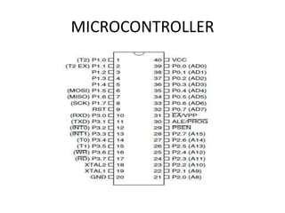
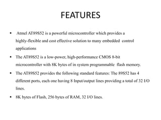
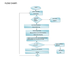
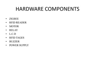
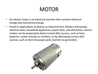
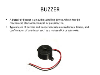
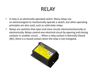
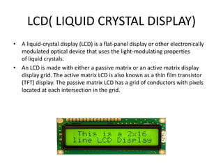
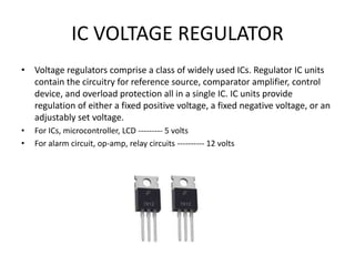
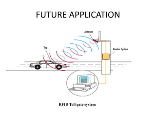
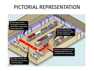
ZIGBEE BASED TROLLEY CART ACCESS SYSTEM
USING RFID FOR SHOPPING
GUIDED BY:
MS.K.SUPRIYA
BY:
R.UDAYA SRI
V.S SAILASYA
P.SAMUEL
AIM
• The aim of this project is to improve the speed of purchase by using RFID.
• This project is designed to use the RFID based security system application
in the shopping trolley.
CONTENTS
• INTRODUCTION
• EXISTING METHOD
• PROPOSED METHOD
• BLOCK DIAGRAM
• MICROCONTROLLER
• FEATURES OF AT89S52
• FLOWCHART
• HARDWARE COMPONENTS
• KEIL MICRO VISION
• ADVANTAGES
• APPLICATIONS
• RESULT
• CONCLUSION
INTRODUCTION
• A Smart Shopping System has the feature of automatic billing when a
customer carries a basketful of items through RFID antennas.
• The RFID antennas sense these items using multiple RFID Tag reader and
generates the bill automatically. The RFID tags used on the items will be
Ultra High Frequency(UHF).
EXISTING METHOD
• Currently available method in shopping malls is barcode method.
• In this method there are barcode labels on each product which can be read through
specially designed barcode readers.
PROPOSED METHOD
• Users can be registered or nonregistered. The registered user will be givena
NFC card(Smart Card)which can be recharged by paying required amount
in the same shop.
• If the customer is busy then he can just shop and shows his card for
payment. Nonregistered users need to pay the cash at the counter when the
bill is generated within few seconds.
BLOCK DIAGRAM (TRANSMITTER)
BLOCK DIAGRAM:
AT89S52
L.C.D
P.S.U
RFID
READER1
ZIGBEE
TRANSMITTER
BLOCK DIAGRAM(RECIEVER)
AT89S52
L.C.D
P.S.U
ZIGBEE
RECEIVER
Relay Motor
Buzzer
MICROCONTROLLER
FEATURES
 Atmel AT89S52 is a powerful microcontroller which provides a
highly-flexible and cost effective solution to many embedded control
applications
 The AT89S52 is a low-power, high-performance CMOS 8-bit
microcontroller with 8K bytes of in system programmable flash memory.
 The AT89S52 provides the following standard features: The 89S52 has 4
different ports, each one having 8 Input/output lines providing a total of 32 I/O
lines.
 8K bytes of Flash, 256 bytes of RAM, 32 I/O lines.
FLOW CHART:
HARDWARE COMPONENTS
• ZIGBEE
• RFID READER
• MOTOR
• RELAY
• L.C.D
• RFID TAGES
• BUZZER
• POWER SUPPLY
RFID READER
• A radio frequency identification reader (RFID reader) is a device used to
gather information from an RFID tag, which is used to track individual
objects. Radio waves are used to transfer data from the tag to a reader.
• The reader has an antenna that emits radio waves; the tag responds by
sending back its data.
• The reader has two basic components – A scanning antenna ,A transceiver
with a decoder to interpret the data
RFID TAGS
• RFID tag is an object that can be applied to or incorporated into a product,
animal, or person for the purpose of identification and tracking using radio
waves.
• The RFID tag it must be within the range of an RFID reader, which ranges
from 3 to 300 feet.
• Frequency ranges vary from low frequencies of 125 to 134 kHz and 140 to
148.5 kHz, and high frequencies of 850 to 950 MHz and 2.4 to 2.5 GHz.
Wavelengths in the 2.4 GHz.
ZIGBEE
• ZigBee is a low-cost, low-power, wireless mesh network standard targeted
at the wide development of long battery life devices in wireless control
and monitoring applications.
• 2.4 GHz in most jurisdictions worldwide; 784 MHz in China, 868 MHz in
Europe and 915 MHz in the USA and Australia. Data rates vary from
20 kbit/s (868 MHz band) to 250 kbit/s (2.4 GHz band).
RS232 SERIAL CONNECTORS
• RS-232 is a standard for serial communication transmission of data.
• It formally defines the signals connecting between a DTE (data terminal
equipment) such as a computer terminal, and a DCE (data circuit-
terminating equipment or data communication equipment), such as a
modem.
• RS-232 stands for Recommend Standard number 232 and C is the latest
revision of the standard. The serial ports on most computers use a subset
of the RS-232C standard. The full RS-232C standard specifies a 25-pin "D"
connector of which 22 pins are used.
MOTOR
• An electric motor is an electrical machine that converts electrical
energy into mechanical energy.
• Found in applications as diverse as industrial fans, blowers and pumps,
machine tools, household appliances, power tools, and disk drives, electric
motors can be powered by direct current (DC) sources, such as from
batteries, motor vehicles or rectifiers, or by alternating current (AC)
sources, such as from the power grid, inverters or generators.
BUZZER
• A buzzer or beeper is an audio signalling device, which may be
mechanical, electromechanical, or piezoelectric.
• Typical uses of buzzers and beepers include alarm devices, timers, and
confirmation of user input such as a mouse click or keystroke.
RELAY
• A relay is an electrically operated switch. Many relays use
an electromagnet to mechanically operate a switch, but other operating
principles are also used, such as solid-state relays.
• Relays are switches that open and close circuits electromechanically or
electronically. Relays control one electrical circuit by opening and closing
contacts in another circuit. ... When a relay contact is Normally Closed
(NC), there is a closed contact when the relay is not energized.
LCD( LIQUID CRYSTAL DISPLAY)
• A liquid-crystal display (LCD) is a flat-panel display or other electronically
modulated optical device that uses the light-modulating properties
of liquid crystals.
• An LCD is made with either a passive matrix or an active matrix display
display grid. The active matrix LCD is also known as a thin film transistor
(TFT) display. The passive matrix LCD has a grid of conductors with pixels
located at each intersection in the grid.
POWER SUPPLY
• A power supply is an electronic device that supplies electric energy to
an electrical load.
• The ac voltage, typically 220V rms, is connected to a transformer, which
steps that ac voltage down to the level of the desired dc output.
•
IC REGULATOR LOAD
TRANSFORMER
RECTIFIER FILTER
POWER SUPPLY
•
TRANSFORMER
• The potential transformer will step down the power supply voltage (0-230V) to (0-
6V) level. Then the secondary of the potential transformer will be connected to
the precision rectifier, which is constructed with the help of op–amp.
• The advantages of using precision rectifier are it will give peak voltage output as
DC, rest of the circuits will give only RMS output.
BRIDGE RECTIFIER
• When four diodes are connected as shown in figure, the circuit is called as bridge
rectifier. The input to the circuit is applied to the diagonally opposite corners of
the network, and the output is taken from the remaining two corners.
• One advantage of a bridge rectifier over a conventional full-wave rectifier is that
with a given transformer the bridge rectifier produces a voltage output.
• The maximum voltage that appears across the load resistor is nearly-but never
exceeds-500 v0lts.
IC VOLTAGE REGULATOR
• Voltage regulators comprise a class of widely used ICs. Regulator IC units
contain the circuitry for reference source, comparator amplifier, control
device, and overload protection all in a single IC. IC units provide
regulation of either a fixed positive voltage, a fixed negative voltage, or an
adjustably set voltage.
• For ICs, microcontroller, LCD --------- 5 volts
• For alarm circuit, op-amp, relay circuits ---------- 12 volts
KEIL MICRO VISION
 For programming the microcontroller we have used the best
micro controller software called “Keil”.
 By using this keil software you can compile C program and can
check for errors.
 After compiling the code we have created the .HEX file.
 The .HEX is to be dumped in the AT89S52 using topwin dumper
ADVANTAGES
• Reduces scanning time
• Personalization of items
• Maintains History of purchased products
• Provides information regarding Discounts and Offers
APPLICATIONS
• Shopping malls
• Grocery Stores
FUTURE APPLICATION
RFID Toll gate system
PICTORIAL REPRESENTATION
CONCLUSION
 As the technology grows day by day, we can imagine about
the future in which thing we may occupy every place.
 This project simplifies the billing process, makes it swift &
increases the security using RFID technique. This will take
the overall shopping experience to a different level.
THANK YOU 

Zigbee based trolley cart access system using rfid

  • 1.
    ZIGBEE BASED TROLLEYCART ACCESS SYSTEM USING RFID FOR SHOPPING GUIDED BY: MS.K.SUPRIYA BY: R.UDAYA SRI V.S SAILASYA P.SAMUEL
  • 2.
    AIM • The aimof this project is to improve the speed of purchase by using RFID. • This project is designed to use the RFID based security system application in the shopping trolley.
  • 3.
    CONTENTS • INTRODUCTION • EXISTINGMETHOD • PROPOSED METHOD • BLOCK DIAGRAM • MICROCONTROLLER • FEATURES OF AT89S52 • FLOWCHART • HARDWARE COMPONENTS • KEIL MICRO VISION • ADVANTAGES • APPLICATIONS • RESULT • CONCLUSION
  • 4.
    INTRODUCTION • A SmartShopping System has the feature of automatic billing when a customer carries a basketful of items through RFID antennas. • The RFID antennas sense these items using multiple RFID Tag reader and generates the bill automatically. The RFID tags used on the items will be Ultra High Frequency(UHF).
  • 5.
    EXISTING METHOD • Currentlyavailable method in shopping malls is barcode method. • In this method there are barcode labels on each product which can be read through specially designed barcode readers.
  • 6.
    PROPOSED METHOD • Userscan be registered or nonregistered. The registered user will be givena NFC card(Smart Card)which can be recharged by paying required amount in the same shop. • If the customer is busy then he can just shop and shows his card for payment. Nonregistered users need to pay the cash at the counter when the bill is generated within few seconds.
  • 7.
    BLOCK DIAGRAM (TRANSMITTER) BLOCKDIAGRAM: AT89S52 L.C.D P.S.U RFID READER1 ZIGBEE TRANSMITTER
  • 8.
  • 9.
  • 10.
    FEATURES  Atmel AT89S52is a powerful microcontroller which provides a highly-flexible and cost effective solution to many embedded control applications  The AT89S52 is a low-power, high-performance CMOS 8-bit microcontroller with 8K bytes of in system programmable flash memory.  The AT89S52 provides the following standard features: The 89S52 has 4 different ports, each one having 8 Input/output lines providing a total of 32 I/O lines.  8K bytes of Flash, 256 bytes of RAM, 32 I/O lines.
  • 11.
  • 12.
    HARDWARE COMPONENTS • ZIGBEE •RFID READER • MOTOR • RELAY • L.C.D • RFID TAGES • BUZZER • POWER SUPPLY
  • 13.
    RFID READER • Aradio frequency identification reader (RFID reader) is a device used to gather information from an RFID tag, which is used to track individual objects. Radio waves are used to transfer data from the tag to a reader. • The reader has an antenna that emits radio waves; the tag responds by sending back its data. • The reader has two basic components – A scanning antenna ,A transceiver with a decoder to interpret the data
  • 14.
    RFID TAGS • RFIDtag is an object that can be applied to or incorporated into a product, animal, or person for the purpose of identification and tracking using radio waves. • The RFID tag it must be within the range of an RFID reader, which ranges from 3 to 300 feet. • Frequency ranges vary from low frequencies of 125 to 134 kHz and 140 to 148.5 kHz, and high frequencies of 850 to 950 MHz and 2.4 to 2.5 GHz. Wavelengths in the 2.4 GHz.
  • 15.
    ZIGBEE • ZigBee isa low-cost, low-power, wireless mesh network standard targeted at the wide development of long battery life devices in wireless control and monitoring applications. • 2.4 GHz in most jurisdictions worldwide; 784 MHz in China, 868 MHz in Europe and 915 MHz in the USA and Australia. Data rates vary from 20 kbit/s (868 MHz band) to 250 kbit/s (2.4 GHz band).
  • 16.
    RS232 SERIAL CONNECTORS •RS-232 is a standard for serial communication transmission of data. • It formally defines the signals connecting between a DTE (data terminal equipment) such as a computer terminal, and a DCE (data circuit- terminating equipment or data communication equipment), such as a modem. • RS-232 stands for Recommend Standard number 232 and C is the latest revision of the standard. The serial ports on most computers use a subset of the RS-232C standard. The full RS-232C standard specifies a 25-pin "D" connector of which 22 pins are used.
  • 17.
    MOTOR • An electricmotor is an electrical machine that converts electrical energy into mechanical energy. • Found in applications as diverse as industrial fans, blowers and pumps, machine tools, household appliances, power tools, and disk drives, electric motors can be powered by direct current (DC) sources, such as from batteries, motor vehicles or rectifiers, or by alternating current (AC) sources, such as from the power grid, inverters or generators.
  • 18.
    BUZZER • A buzzeror beeper is an audio signalling device, which may be mechanical, electromechanical, or piezoelectric. • Typical uses of buzzers and beepers include alarm devices, timers, and confirmation of user input such as a mouse click or keystroke.
  • 19.
    RELAY • A relayis an electrically operated switch. Many relays use an electromagnet to mechanically operate a switch, but other operating principles are also used, such as solid-state relays. • Relays are switches that open and close circuits electromechanically or electronically. Relays control one electrical circuit by opening and closing contacts in another circuit. ... When a relay contact is Normally Closed (NC), there is a closed contact when the relay is not energized.
  • 20.
    LCD( LIQUID CRYSTALDISPLAY) • A liquid-crystal display (LCD) is a flat-panel display or other electronically modulated optical device that uses the light-modulating properties of liquid crystals. • An LCD is made with either a passive matrix or an active matrix display display grid. The active matrix LCD is also known as a thin film transistor (TFT) display. The passive matrix LCD has a grid of conductors with pixels located at each intersection in the grid.
  • 21.
    POWER SUPPLY • Apower supply is an electronic device that supplies electric energy to an electrical load. • The ac voltage, typically 220V rms, is connected to a transformer, which steps that ac voltage down to the level of the desired dc output. • IC REGULATOR LOAD TRANSFORMER RECTIFIER FILTER
  • 22.
  • 23.
    TRANSFORMER • The potentialtransformer will step down the power supply voltage (0-230V) to (0- 6V) level. Then the secondary of the potential transformer will be connected to the precision rectifier, which is constructed with the help of op–amp. • The advantages of using precision rectifier are it will give peak voltage output as DC, rest of the circuits will give only RMS output.
  • 24.
    BRIDGE RECTIFIER • Whenfour diodes are connected as shown in figure, the circuit is called as bridge rectifier. The input to the circuit is applied to the diagonally opposite corners of the network, and the output is taken from the remaining two corners. • One advantage of a bridge rectifier over a conventional full-wave rectifier is that with a given transformer the bridge rectifier produces a voltage output. • The maximum voltage that appears across the load resistor is nearly-but never exceeds-500 v0lts.
  • 25.
    IC VOLTAGE REGULATOR •Voltage regulators comprise a class of widely used ICs. Regulator IC units contain the circuitry for reference source, comparator amplifier, control device, and overload protection all in a single IC. IC units provide regulation of either a fixed positive voltage, a fixed negative voltage, or an adjustably set voltage. • For ICs, microcontroller, LCD --------- 5 volts • For alarm circuit, op-amp, relay circuits ---------- 12 volts
  • 26.
    KEIL MICRO VISION For programming the microcontroller we have used the best micro controller software called “Keil”.  By using this keil software you can compile C program and can check for errors.  After compiling the code we have created the .HEX file.  The .HEX is to be dumped in the AT89S52 using topwin dumper
  • 27.
    ADVANTAGES • Reduces scanningtime • Personalization of items • Maintains History of purchased products • Provides information regarding Discounts and Offers
  • 28.
  • 29.
  • 30.
  • 31.
    CONCLUSION  As thetechnology grows day by day, we can imagine about the future in which thing we may occupy every place.  This project simplifies the billing process, makes it swift & increases the security using RFID technique. This will take the overall shopping experience to a different level.
  • 32.