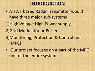
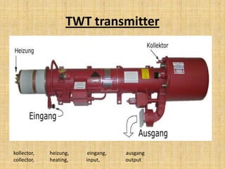
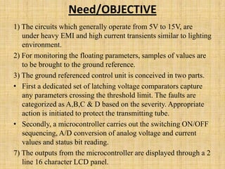
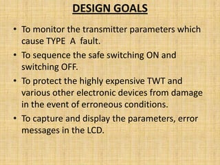
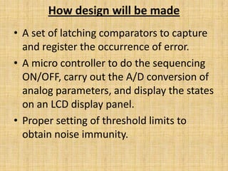
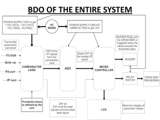
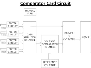
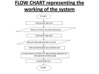


This document describes a monitoring, protection, and control module for a radar transmitter. The module monitors key transmitter parameters, protects the system by triggering faults if parameters exceed thresholds, and controls the transmitter's on/off sequencing. It uses comparators to detect parameter faults, a microcontroller for control and interfacing, an ADC to convert analog signals, and an LCD for output display. The design aims to safely monitor and protect the expensive transmitter components.


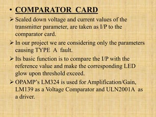
![Interfacing technique with 8085- ADC[0808]](https://cdn.slidesharecdn.com/ss_thumbnails/adc-160307140900-thumbnail.jpg?width=640&height=640&fit=bounds)


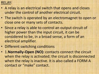
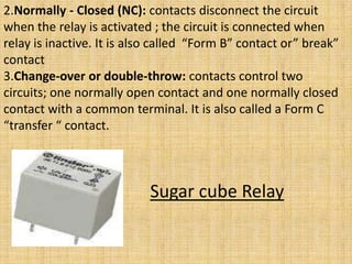
![MICROPROCESSOR%20RELAYS%20HARDWARE[1].ppt](https://cdn.slidesharecdn.com/ss_thumbnails/microprocessor20relays20hardware1-250720152025-8ee37ffd-thumbnail.jpg?width=640&height=640&fit=bounds)


