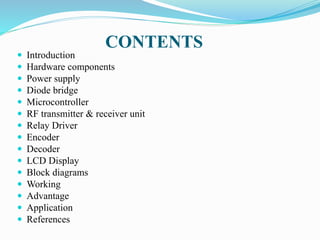
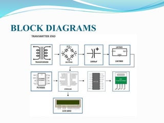
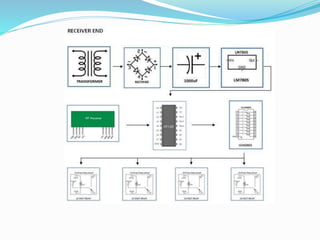
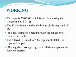
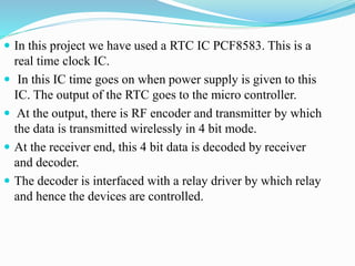
AMBEDKARNAGAR, U.P.
MAJOR PROJECT ON
AUTOMATIC WIRELESS POWER GRID CONTROL
(DISTRIBUTION UNIT)
GUIDED BY :
Mr. NITISH KUMAR YADAV
(ASST. PROFESSOR)
SUBMITTED BY :
- AJAY KUMAR (1573720902)
- BRIJESH KUMAR (1473720012)
- NAVNEET SINGH SAURABH
(1573720903)
CONTENTS
 Introduction
 Hardware components
 Power supply
 Diode bridge
 Microcontroller
 RF transmitter & receiver unit
 Relay Driver
 Encoder
 Decoder
 LCD Display
 Block diagrams
 Working
 Advantage
 Application
 References
INTRDUCTION
 Automation of systems has become the demand of the day.
 Newer technology has made everything automatic and self
repairable.
 In fact most of the developed systems are impossible to be
controlled by human beings.
 In this project we are controlling a power grid and
different units are controlled on the basis of time. The
control unit and the execution unit are wirelessly
connected over RF protocol.
HARDWARE COMPONENTS
 Power supply
 Diode bridge
 Capacitor
 AT89S8253 Microcontroller
 RF transmitter & receiver unit
 Relay Driver (ULN2803)
 Encoder
 Decoder
 LCD Display
POWER SUPPLY
 The power supply consists of a step down transformer
230/12V, which steps down the voltage to 12V AC.
 This is converted to DC using a Bridge rectifier.
 The ripples are removed using a capacitive filter and it is
then regulated to +5V using a voltage regulator 7805
which is required for the operation of the microcontroller
and other components.
DIODE BRIDGE
 A diode bridge is an arrangement of four (or
more) diodes in a bridge circuit configuration that
provides the same polarity of output for either polarity of
input.
 When used in its most common application, for
conversion of an alternating current (AC) input into
a direct current (DC) output, it is known as
a bridge rectifier.
CAPACITORS
 To store electricity, or electrical energy.
 Also functions as filter, passing AC, and blocking DC.
 Apply DC voltage- electric charge is stored on each
electrode.
 Three types of capacitor i.e. ceramic capacitor &
electrolytic capacitor and variable.
 Polarized capacitors – Electrolytic.
 Un-Polarized capacitors – ceramic.
 Variable capacitors.
MICROCONTROLLER
 This unit is the brain of the system. This is responsible for
the full control of the system.
 The microcontroller used here is a common 8 bit Atmel
microcontroller AT89s8253.
 It is a low-power, high-performance CMOS 8-bit
microcontroller with12K bytes of In-System
Programmable (ISP) Flash program memory and 2K bytes
of EEPROM data memory.
 It has 32 programmable input output lines.
RF transmitter & receiver unit
 This RF module comprises of an RF Transmitter and
an RF Receiver. The transmitter/receiver (Tx/Rx) pair
operates at a frequency of 434 MHz .
 An RF transmitter receives serial data and transmits it
wirelessly through RF through its antenna connected at
pin4.
 The transmission occurs at the rate of 1Kbps - 10Kbps.
 The transmitted data is received by an RF receiver
operating at the same frequency as that of the transmitter.
RELAY DRIVER
 ULN2803 is a current driver IC which drives the relay.
 The eight NPN Darlington connected transistors in this family
of arrays are ideally suited for interfacing between low logic
level digital circuitry (such as TTL, CMOS or PMOS/NMOS)
and the higher current/voltage requirements of lamps, relays,
printer hammers or other similar loads for a broad range of
computer, industrial, and consumer applications.
 All devices feature open–collector outputs and freewheeling
clamp diodes for transient Suppression.
 The ULN2803 is designed to be compatible with standard TTL
families while the ULN2804 is optimized for 6 to 15 volt high
level CMOS or PMOS.
ENCODER
 HT12E is an encoder integrated circuit of 212 series
of encoders.
 They are paired with 212 series of decoders for use in
remote control system applications.
 It is mainly used in interfacing RF and infrared
circuits.
DECODER
 HT12D is a decoder integrated circuit that belongs to
212 series of decoders.
 This series of decoders are mainly used for remote
control system applications, like burglar alarm, car
door controller, security system etc.
 It is mainly provided to interface RF and infrared
circuits.
LCD Display
 Is an electronic display module.
 16x2 LCD display is very basic module and is very commonly
used in various devices and circuits.
 16x2 LCD means it can display 16 characters per line and there
are 2 such lines.
 Has two registers namely, Command and Data.
 The command register stores the command instructions.
 The data register stores the data to be displayed on the LCD.
 The data is the ASCII value of the character to be displayed on
the LCD.
BLOCK DIAGRAMS
WORKING
 The input is 230V AC which is step down using the
transformer (12-0-12) .
 The 12V ac input is fed to the bridge diode to gives 12V
DC.
 This DC voltage is filtered through the capacitor to
remove the ripples.
 The filtered DC is fed to 7805 regulator to fetch +5v
regulated output.
 This regulated voltage is given to all the components to
function properly.
 In this project we have used a RTC IC PCF8583. This is a
real time clock IC.
 In this IC time goes on when power supply is given to this
IC. The output of the RTC goes to the micro controller.
 At the output, there is RF encoder and transmitter by which
the data is transmitted wirelessly in 4 bit mode.
 At the receiver end, this 4 bit data is decoded by receiver
and decoder.
 The decoder is interfaced with a relay driver by which relay
and hence the devices are controlled.
ADVANTAGES
 It is user-friendly.
 Safer to use.
 Reduces the time of switching due to automation.
 Requires least maintenance.
APPLICATIONS
 Hardware Automation.
 Control system design.
 Used at electricity distribution.
 Time based allocation for industrial machinery to work.
Reference
http://www.learningaboutelectronics.com
http://www.gadgetronicx.com
https://electrosome.com
http://www.gadgetronicx.com
www.electrical4u.com
THANK YOU

AUTOMATIC WIRELESS POWER GRID CONTROL

  • 1.
    AMBEDKARNAGAR, U.P. MAJOR PROJECTON AUTOMATIC WIRELESS POWER GRID CONTROL (DISTRIBUTION UNIT) GUIDED BY : Mr. NITISH KUMAR YADAV (ASST. PROFESSOR) SUBMITTED BY : - AJAY KUMAR (1573720902) - BRIJESH KUMAR (1473720012) - NAVNEET SINGH SAURABH (1573720903)
  • 2.
    CONTENTS  Introduction  Hardwarecomponents  Power supply  Diode bridge  Microcontroller  RF transmitter & receiver unit  Relay Driver  Encoder  Decoder  LCD Display  Block diagrams  Working  Advantage  Application  References
  • 3.
    INTRDUCTION  Automation ofsystems has become the demand of the day.  Newer technology has made everything automatic and self repairable.  In fact most of the developed systems are impossible to be controlled by human beings.  In this project we are controlling a power grid and different units are controlled on the basis of time. The control unit and the execution unit are wirelessly connected over RF protocol.
  • 4.
    HARDWARE COMPONENTS  Powersupply  Diode bridge  Capacitor  AT89S8253 Microcontroller  RF transmitter & receiver unit  Relay Driver (ULN2803)  Encoder  Decoder  LCD Display
  • 5.
    POWER SUPPLY  Thepower supply consists of a step down transformer 230/12V, which steps down the voltage to 12V AC.  This is converted to DC using a Bridge rectifier.  The ripples are removed using a capacitive filter and it is then regulated to +5V using a voltage regulator 7805 which is required for the operation of the microcontroller and other components.
  • 6.
    DIODE BRIDGE  Adiode bridge is an arrangement of four (or more) diodes in a bridge circuit configuration that provides the same polarity of output for either polarity of input.  When used in its most common application, for conversion of an alternating current (AC) input into a direct current (DC) output, it is known as a bridge rectifier.
  • 7.
    CAPACITORS  To storeelectricity, or electrical energy.  Also functions as filter, passing AC, and blocking DC.  Apply DC voltage- electric charge is stored on each electrode.  Three types of capacitor i.e. ceramic capacitor & electrolytic capacitor and variable.  Polarized capacitors – Electrolytic.  Un-Polarized capacitors – ceramic.  Variable capacitors.
  • 8.
    MICROCONTROLLER  This unitis the brain of the system. This is responsible for the full control of the system.  The microcontroller used here is a common 8 bit Atmel microcontroller AT89s8253.  It is a low-power, high-performance CMOS 8-bit microcontroller with12K bytes of In-System Programmable (ISP) Flash program memory and 2K bytes of EEPROM data memory.  It has 32 programmable input output lines.
  • 9.
    RF transmitter &receiver unit  This RF module comprises of an RF Transmitter and an RF Receiver. The transmitter/receiver (Tx/Rx) pair operates at a frequency of 434 MHz .  An RF transmitter receives serial data and transmits it wirelessly through RF through its antenna connected at pin4.  The transmission occurs at the rate of 1Kbps - 10Kbps.  The transmitted data is received by an RF receiver operating at the same frequency as that of the transmitter.
  • 10.
    RELAY DRIVER  ULN2803is a current driver IC which drives the relay.  The eight NPN Darlington connected transistors in this family of arrays are ideally suited for interfacing between low logic level digital circuitry (such as TTL, CMOS or PMOS/NMOS) and the higher current/voltage requirements of lamps, relays, printer hammers or other similar loads for a broad range of computer, industrial, and consumer applications.  All devices feature open–collector outputs and freewheeling clamp diodes for transient Suppression.  The ULN2803 is designed to be compatible with standard TTL families while the ULN2804 is optimized for 6 to 15 volt high level CMOS or PMOS.
  • 11.
    ENCODER  HT12E isan encoder integrated circuit of 212 series of encoders.  They are paired with 212 series of decoders for use in remote control system applications.  It is mainly used in interfacing RF and infrared circuits.
  • 12.
    DECODER  HT12D isa decoder integrated circuit that belongs to 212 series of decoders.  This series of decoders are mainly used for remote control system applications, like burglar alarm, car door controller, security system etc.  It is mainly provided to interface RF and infrared circuits.
  • 13.
    LCD Display  Isan electronic display module.  16x2 LCD display is very basic module and is very commonly used in various devices and circuits.  16x2 LCD means it can display 16 characters per line and there are 2 such lines.  Has two registers namely, Command and Data.  The command register stores the command instructions.  The data register stores the data to be displayed on the LCD.  The data is the ASCII value of the character to be displayed on the LCD.
  • 14.
  • 16.
    WORKING  The inputis 230V AC which is step down using the transformer (12-0-12) .  The 12V ac input is fed to the bridge diode to gives 12V DC.  This DC voltage is filtered through the capacitor to remove the ripples.  The filtered DC is fed to 7805 regulator to fetch +5v regulated output.  This regulated voltage is given to all the components to function properly.
  • 17.
     In thisproject we have used a RTC IC PCF8583. This is a real time clock IC.  In this IC time goes on when power supply is given to this IC. The output of the RTC goes to the micro controller.  At the output, there is RF encoder and transmitter by which the data is transmitted wirelessly in 4 bit mode.  At the receiver end, this 4 bit data is decoded by receiver and decoder.  The decoder is interfaced with a relay driver by which relay and hence the devices are controlled.
  • 18.
    ADVANTAGES  It isuser-friendly.  Safer to use.  Reduces the time of switching due to automation.  Requires least maintenance.
  • 19.
    APPLICATIONS  Hardware Automation. Control system design.  Used at electricity distribution.  Time based allocation for industrial machinery to work.
  • 20.
  • 21.