Downloaded 101 times


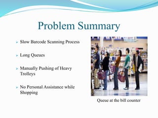
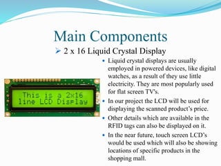
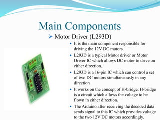
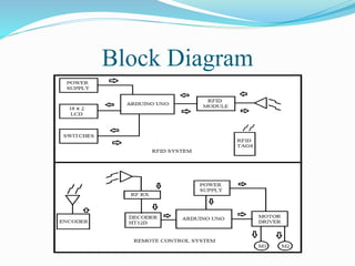

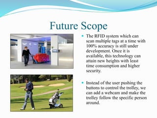


This document describes a smart shopping trolley project that uses RFID technology to automatically scan items placed in the trolley and display the running bill total. The trolley can also be remotely controlled to help elderly or disabled shoppers. Main components include an RFID reader/writer, microcontroller, LCD display, motor driver and remote control module. The system is intended to reduce checkout times and provide assistance to users. Future enhancements could include an interactive display showing item locations and a remote control system using computer vision.


![SMART_SHOPPING_TROLLEY_WITH_AUTOMATED_BILLING_USING_ARDUINO_(2)_[Autosaved][1...](https://cdn.slidesharecdn.com/ss_thumbnails/smartshoppingtrolleywithautomatedbillingusingarduino2autosaved1-240113111847-903800d0-thumbnail.jpg?width=640&height=640&fit=bounds)


