Download to read offline


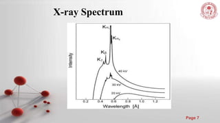
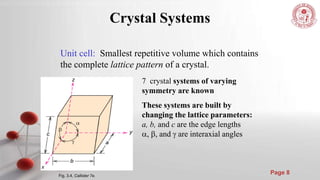


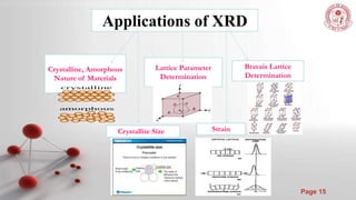

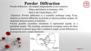


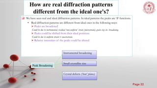
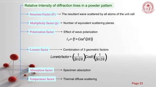


The document discusses the principles and techniques of x-ray crystallography, including how x-rays are produced and used to determine crystal structures by measuring diffraction patterns and applying Bragg's law. It also describes how real diffraction patterns may differ from ideal ones due to factors like strain, crystallite size, and instrumentation.