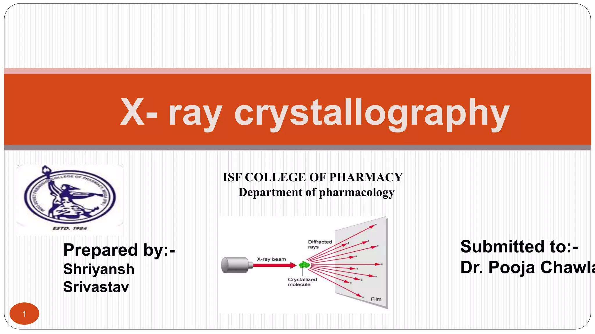
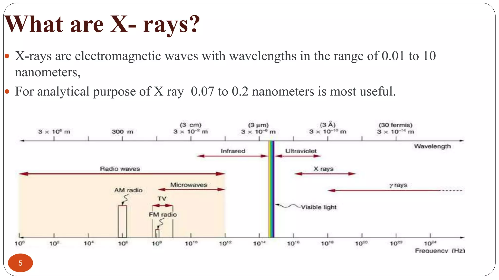
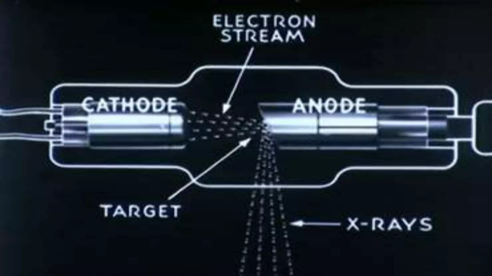
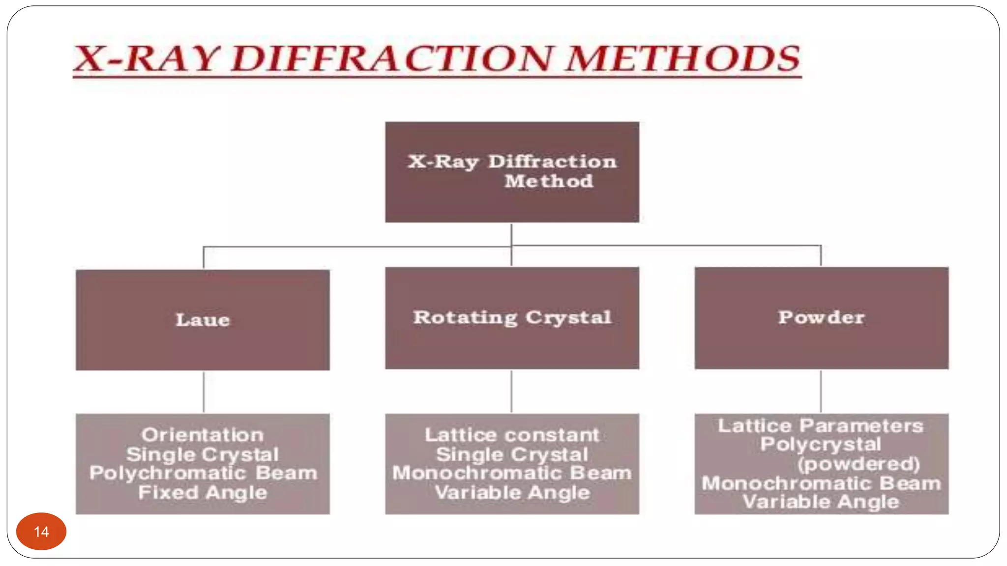
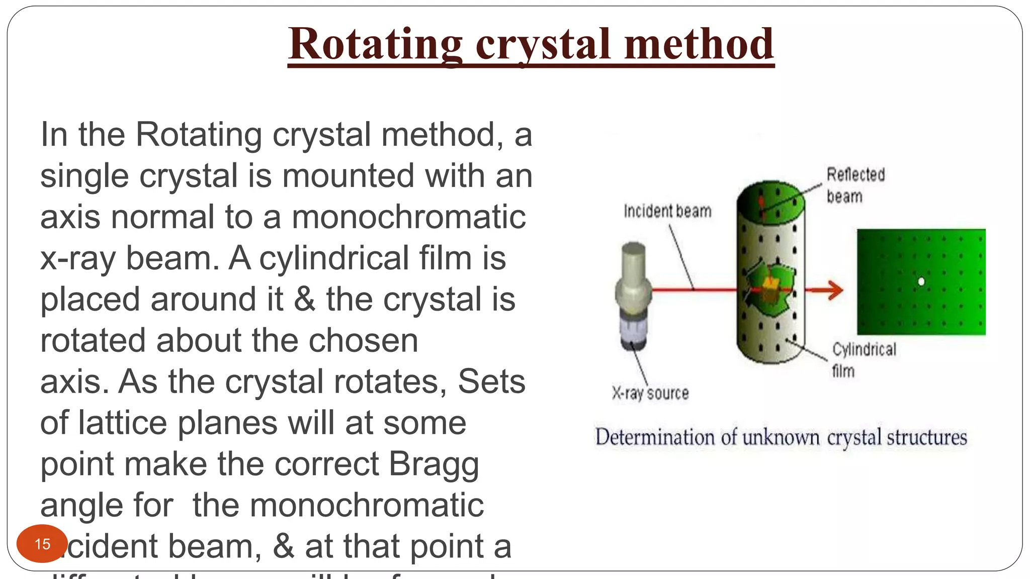
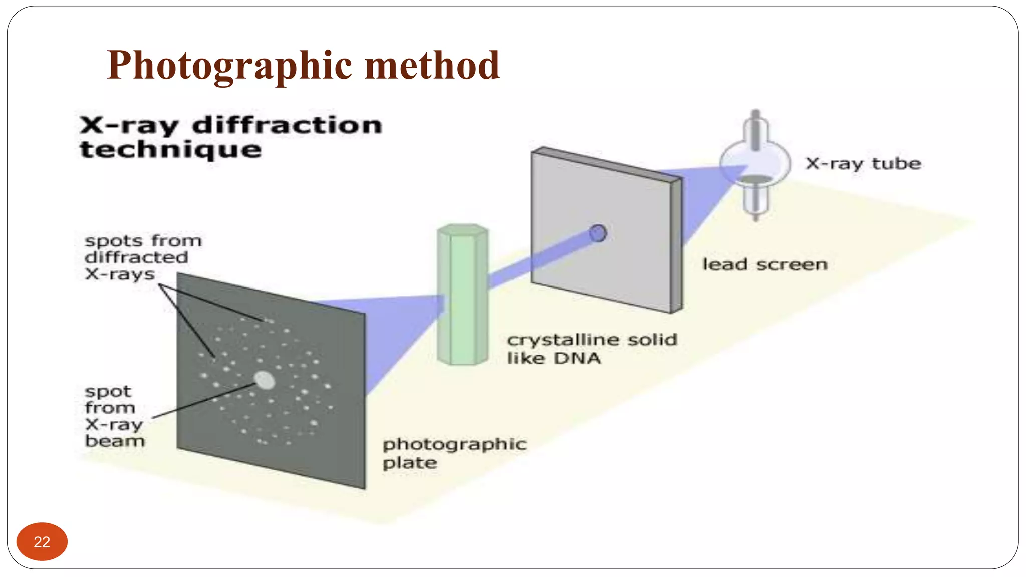
1
X- ray crystallography
ISF COLLEGE OF PHARMACY
Department of pharmacology
Prepared by:-
Shriyansh
Srivastav
Submitted to:-
Dr. Pooja Chawla
Contents
2
 Introduction
 History of X rays
 Production of X rays
 X ray diffraction
 Bragg’s law
 Crystal structures
 X ray diffraction methods
 Instrumentation
 Applications
INTRODUCTION
3
 X-ray crystallography (XRC) is the experimental science
determining the atomic and molecular structure of the crystal, in
which the crystalline structure causes a beam of incident x-
rays to diffract into many specific direction
 X-ray crystallography is a powerful technique for visualizing the
structure of protein.
History of X- rays
4
 X ray were discovered in 1895 by the German physicist
‘Wilhelm conrad rontgen’and were so named because their
nature was unknown at that time.
 He was awarded the nobel prize for physics in 1901.
What are X- rays?
5
 X-rays are electromagnetic waves with wavelengths in the range of 0.01 to 10
nanometers,
 For analytical purpose of X ray 0.07 to 0.2 nanometers is most useful.
How X- rays are produced?
6
 X-Ray are produced by two method -
 (a) When high velocity of electron will knock out the electron from target atom,
and due to loss of energy X-ray will produce.
 (b) High velocity of electron will strike the anode material in a discharge tube
which result production of X-rays.
7
X- ray
diffraction
X- ray
absorption
8
 It is based on scattering of x
rays by crystals
 This method is used for
identify the crystal structure of
any solid compound with high
degree of specification and
accuracy
 It is based on the principle of absorption of x
rays by the sample
 When a beam of x ray pass through the
sample and the fraction of light absorbed is
considered to be the measure of
concentration of sample
 It gives information about the absorbing
X ray florescence
It is the emission of characteristic
secondary x rays from a material that
has been excited by being
bombarded with high energy x rays ,
and by measuring the wavelength
and intensity of the generated x rays
analyst can perform qualitative and
quantitative analysis
Different phenomenon caused by x ray irradiation
X ray diffraction
9
 X-ray diffraction, a phenomenon in which the atoms of a crystal by virtue of their uniform
spacing, cause an interference pattern of the waves present in an incident beam of X rays.
When X rays strike the crystal, the crystal diffracts the X-ray beam differently, depending on
its structure and orientation. The diffracted X-ray is collected by an area detector. The
diffraction pattern consists of reflections of different intensity which can be used to determine
the structure of the crystal.
 The resolution of an X-ray diffraction detector is determined by the Bragg equation.
When x-rays are scattered from a crystal lattice, peaks of scattered intensity are observed
which correspond to the following conditions:
 The angle of incidence = angle of scattering.
 The pathlength difference is equal to an integer number of wavelengths.
 The condition for maximum intensity contained in Bragg's law above allow us
to calculate details about the crystal structure, or if the crystal structure is known,
to determine the wavelength of the x-rays incident upon the crystal.
10
11
Crystal structure
12
 In crystallography, the terms crystal system, crystal family, and lattice
system each refer to one of several classes of space groups, lattices, point
groups, or crystals
 The simplest repeating unit in a crystal is called a unit cell. Each unit cell is
defined in terms of lattice points. The points in space about which the particles
are free to vibrate in a crystal. There are 7 different kinds of crystal systems, and
each kind of crystal system has 4 different kinds of centerings (Primitive, Base-
centered, Body-centered, Face-centered). However, not all of the combinations
are unique; some of the combinations are equivalent while other combinations
are not possible due to symmetry reasons.
13
14
Rotating crystal method
In the Rotating crystal method, a
single crystal is mounted with an
axis normal to a monochromatic
x-ray beam. A cylindrical film is
placed around it & the crystal is
rotated about the chosen
axis. As the crystal rotates, Sets
of lattice planes will at some
point make the correct Bragg
angle for the monochromatic
incident beam, & at that point a15
16
The Lattice constant of the crystal can be determined with this
method. For a given wavelength λ if the angle θ at which a
reflection occurs is known, d can be determined by using
Bragg’s Law.
The reflected beams are located on the surfaces of imaginary
cones. By recording the diffraction patterns (both angles &
intensities) for various crystal orientations, one can determine
the shape & size of unit cell as well as the arrangement of atoms
inside the cell.
Powder diffraction method
17
If a powdered crystal is used instead of a
single crystal, then there is no need to rotate
it, because there will always be some small
crystals at an orientation for which diffraction
is permitted. Here a monochromatic X-ray
beam is incident on a powdered or
polycrystalline sample. Useful for samples
that are difficult to obtain in single crystal
form. The powder method is used to
determine the lattice parameters accurately.
Lattice parameters are the magnitudes of the
primitive vectors a, b and c which define the
18
 For every set of crystal planes, by chance, one or more crystals will be in
the correct orientation to give the correct Bragg angle to satisfy Bragg's
equation.
 Every crystal plane is thus capable of diffraction. Each diffraction line is
made up of a large number of small spots, each from a separate crystal.
 Each spot is so small as to give the appearance of a continuous line
 If a monochromatic X-ray beam is directed at a single crystal, then only one
or two diffracted beams may result.
 For a sample of several randomly orientated single crystals, the diffracted
beams will lie on the surface of several cones.
 The cones may emerge in all directions, forwards and backwards For a
sample of hundreds of crystals (powdered sample), the diffracted beams
form continuous cones.
 A circle of film is used to record the diffraction pattern as shown. Each cone
intersects the film giving diffraction lines. The lines are seen as arcs on the
19
 Production of x rays
 Collimator
 Monochromator
1)Filter
2) Crystal monochromator
 Detectors
1)Photographic methods
2)Counter methods
Instrumentation
20
 Monochromator: The main goal of monochromator is to separate and
transmit a narrow portion of optical signals chosen from a wider range of
wavelength available at the input
1. FILTER: A filter is a window of material that absorbs undesirable radiation but allows the radiation of
required wavelength to pass. e.g.. Zirconium filter which is used for molybdenum radiation.
2. Crystal monochromator:- It is made up of a suitable crystalline material positioned in the x ray beam so
that angle of reflecting planes satisfied the Bragg's equation for required wavelength. e.g. flat crystal
monochromator
 Collimators:- collimator is a device that narrows a beam of particles or
waves. Narrow means to cause the directions of motion to become more
aligned in a specific direction. It is achieved by using a series of closely
spaced, parellel metal plates r by a bundle of tubes, 0.5 or less in
diameter
Detectors
21
 1) Photographic methods:- This is used to determine crystal
structure
 2)Counter Methods :- This is used to determine the intensity of
x rays
It includes:-
-Geiger muller counter
-Scintillation detector
Photographic method
22
Geiger muller counter
23
Scintillation detector
24
25
Applications of XRD
25
 Determination of the structure of the crystals
 Polymers characterisation
 Differentiation between amorphous and crystalline
structure
 Determination of the orientation of the crystalline
structure
 Analysis of milk stone
 Identification of the impurity
 Identification of the fine grained minerals
Reference
26
 Chatwal R G, Anand K S, “Instrumental method of
chemical analysis”, Himalaya publishing house, Page
no:2.303-2.339
 Kamboj C P, “Pharmaceutical analysis- 2 instrumental
method” , Vallabh publication, page no:461-483
 Slideshare

X- ray crystallography, Shriyansh Srivastava, M.Pharm (Department of Pharmacology) INDO SOVIET FRIENDSHIP,PUNJAB

  • 1.
    1 X- ray crystallography ISFCOLLEGE OF PHARMACY Department of pharmacology Prepared by:- Shriyansh Srivastav Submitted to:- Dr. Pooja Chawla
  • 2.
    Contents 2  Introduction  Historyof X rays  Production of X rays  X ray diffraction  Bragg’s law  Crystal structures  X ray diffraction methods  Instrumentation  Applications
  • 3.
    INTRODUCTION 3  X-ray crystallography(XRC) is the experimental science determining the atomic and molecular structure of the crystal, in which the crystalline structure causes a beam of incident x- rays to diffract into many specific direction  X-ray crystallography is a powerful technique for visualizing the structure of protein.
  • 4.
    History of X-rays 4  X ray were discovered in 1895 by the German physicist ‘Wilhelm conrad rontgen’and were so named because their nature was unknown at that time.  He was awarded the nobel prize for physics in 1901.
  • 5.
    What are X-rays? 5  X-rays are electromagnetic waves with wavelengths in the range of 0.01 to 10 nanometers,  For analytical purpose of X ray 0.07 to 0.2 nanometers is most useful.
  • 6.
    How X- raysare produced? 6  X-Ray are produced by two method -  (a) When high velocity of electron will knock out the electron from target atom, and due to loss of energy X-ray will produce.  (b) High velocity of electron will strike the anode material in a discharge tube which result production of X-rays.
  • 7.
  • 8.
    X- ray diffraction X- ray absorption 8 It is based on scattering of x rays by crystals  This method is used for identify the crystal structure of any solid compound with high degree of specification and accuracy  It is based on the principle of absorption of x rays by the sample  When a beam of x ray pass through the sample and the fraction of light absorbed is considered to be the measure of concentration of sample  It gives information about the absorbing X ray florescence It is the emission of characteristic secondary x rays from a material that has been excited by being bombarded with high energy x rays , and by measuring the wavelength and intensity of the generated x rays analyst can perform qualitative and quantitative analysis Different phenomenon caused by x ray irradiation
  • 9.
    X ray diffraction 9 X-ray diffraction, a phenomenon in which the atoms of a crystal by virtue of their uniform spacing, cause an interference pattern of the waves present in an incident beam of X rays. When X rays strike the crystal, the crystal diffracts the X-ray beam differently, depending on its structure and orientation. The diffracted X-ray is collected by an area detector. The diffraction pattern consists of reflections of different intensity which can be used to determine the structure of the crystal.  The resolution of an X-ray diffraction detector is determined by the Bragg equation. When x-rays are scattered from a crystal lattice, peaks of scattered intensity are observed which correspond to the following conditions:  The angle of incidence = angle of scattering.  The pathlength difference is equal to an integer number of wavelengths.  The condition for maximum intensity contained in Bragg's law above allow us to calculate details about the crystal structure, or if the crystal structure is known, to determine the wavelength of the x-rays incident upon the crystal.
  • 10.
  • 11.
  • 12.
    Crystal structure 12  Incrystallography, the terms crystal system, crystal family, and lattice system each refer to one of several classes of space groups, lattices, point groups, or crystals  The simplest repeating unit in a crystal is called a unit cell. Each unit cell is defined in terms of lattice points. The points in space about which the particles are free to vibrate in a crystal. There are 7 different kinds of crystal systems, and each kind of crystal system has 4 different kinds of centerings (Primitive, Base- centered, Body-centered, Face-centered). However, not all of the combinations are unique; some of the combinations are equivalent while other combinations are not possible due to symmetry reasons.
  • 13.
  • 14.
  • 15.
    Rotating crystal method Inthe Rotating crystal method, a single crystal is mounted with an axis normal to a monochromatic x-ray beam. A cylindrical film is placed around it & the crystal is rotated about the chosen axis. As the crystal rotates, Sets of lattice planes will at some point make the correct Bragg angle for the monochromatic incident beam, & at that point a15
  • 16.
    16 The Lattice constantof the crystal can be determined with this method. For a given wavelength λ if the angle θ at which a reflection occurs is known, d can be determined by using Bragg’s Law. The reflected beams are located on the surfaces of imaginary cones. By recording the diffraction patterns (both angles & intensities) for various crystal orientations, one can determine the shape & size of unit cell as well as the arrangement of atoms inside the cell.
  • 17.
    Powder diffraction method 17 Ifa powdered crystal is used instead of a single crystal, then there is no need to rotate it, because there will always be some small crystals at an orientation for which diffraction is permitted. Here a monochromatic X-ray beam is incident on a powdered or polycrystalline sample. Useful for samples that are difficult to obtain in single crystal form. The powder method is used to determine the lattice parameters accurately. Lattice parameters are the magnitudes of the primitive vectors a, b and c which define the
  • 18.
    18  For everyset of crystal planes, by chance, one or more crystals will be in the correct orientation to give the correct Bragg angle to satisfy Bragg's equation.  Every crystal plane is thus capable of diffraction. Each diffraction line is made up of a large number of small spots, each from a separate crystal.  Each spot is so small as to give the appearance of a continuous line  If a monochromatic X-ray beam is directed at a single crystal, then only one or two diffracted beams may result.  For a sample of several randomly orientated single crystals, the diffracted beams will lie on the surface of several cones.  The cones may emerge in all directions, forwards and backwards For a sample of hundreds of crystals (powdered sample), the diffracted beams form continuous cones.  A circle of film is used to record the diffraction pattern as shown. Each cone intersects the film giving diffraction lines. The lines are seen as arcs on the
  • 19.
    19  Production ofx rays  Collimator  Monochromator 1)Filter 2) Crystal monochromator  Detectors 1)Photographic methods 2)Counter methods Instrumentation
  • 20.
    20  Monochromator: Themain goal of monochromator is to separate and transmit a narrow portion of optical signals chosen from a wider range of wavelength available at the input 1. FILTER: A filter is a window of material that absorbs undesirable radiation but allows the radiation of required wavelength to pass. e.g.. Zirconium filter which is used for molybdenum radiation. 2. Crystal monochromator:- It is made up of a suitable crystalline material positioned in the x ray beam so that angle of reflecting planes satisfied the Bragg's equation for required wavelength. e.g. flat crystal monochromator  Collimators:- collimator is a device that narrows a beam of particles or waves. Narrow means to cause the directions of motion to become more aligned in a specific direction. It is achieved by using a series of closely spaced, parellel metal plates r by a bundle of tubes, 0.5 or less in diameter
  • 21.
    Detectors 21  1) Photographicmethods:- This is used to determine crystal structure  2)Counter Methods :- This is used to determine the intensity of x rays It includes:- -Geiger muller counter -Scintillation detector
  • 22.
  • 23.
  • 24.
  • 25.
    25 Applications of XRD 25 Determination of the structure of the crystals  Polymers characterisation  Differentiation between amorphous and crystalline structure  Determination of the orientation of the crystalline structure  Analysis of milk stone  Identification of the impurity  Identification of the fine grained minerals
  • 26.
    Reference 26  Chatwal RG, Anand K S, “Instrumental method of chemical analysis”, Himalaya publishing house, Page no:2.303-2.339  Kamboj C P, “Pharmaceutical analysis- 2 instrumental method” , Vallabh publication, page no:461-483  Slideshare