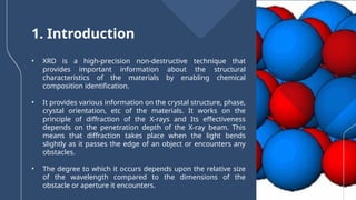
Characterization of Engineering
Materials
Presented by:
Mr. Prasad Pawar (242110006)
Mr. Kumar Shinde (242110007)
Mr. Aditya Mali (242110003)
Under Guidence of :
Dr. W. S. Rathod
V.J.T.I.
X-ray Diffraction
(XRD)
Contents
1. What is X-ray Diffraction
2. Basics of Crystallography
3. Production of X-rays
4. Applications of XRD
5. Instrumental Sources of Error
6. Conclusions
• In 1885, Wilhelm Conrad Rontgen, German
physicist, discovered X-rays.
• These are electromagnetic radiations with a
wavelength ranging from 0.01 to 100 Å, which
corresponds to the frequency in the range of 30PHz
to 300EHz.
History
Bragg’s Law
nλ = 2d sinΘ
• English physicists Sir W.H. Bragg and his son Sir W.L. Bragg developed a
relationship in 1913 to explain why the cleavage faces of crystals appear to
reflect X-ray beams at certain angles of incidence (theta , θ).
• The variable d is the distance between atomic layers in a crystal, and the
variable lambda is the wavelength of the incident X-ray beam; n is an
integer.
• This observation is an example of X-ray wave interference commonly
known as X-ray diffraction (XRD), and was direct evidence for the periodic
atomic structure of crystals postulated for several centuries.
The Braggs were awarded the Nobel Prize in physics in 1915
for their work in determining crystal structures beginning with
NaCl, ZnS and diamond.
Although Bragg's law was used to explain the interference pattern of X-rays scattered by crystals, diffraction has
been developed to study the structure of all states of matter with any beam, e.g., ions, electrons, neutrons, and
protons, with a wavelength similar to the distance between the atomic or molecular structures of interest.
Diffraction Methods
• Radiation sources other than X-Rays such as
neutrons or electrons can also be used in crystal
diffraction experiments.
• The physical basis for the diffraction of
electrons or neutrons is the same as that for the
diffraction of X-Rays. The only difference is in
the mechanism of scattering. The typical
wavelength and energy involved for various
sources are given
Deriving Bragg’s Law: nλ = 2d sinΘ
Constructive interference occurs when the path difference
equals an integer multiple of the wavelength.
n l = AB + BC
AB=BC
n l = 2AB
Sinq=AB/d
AB=dsinq
nλ = 2d sinΘ
Fig. Constructive and Destructive Interference of Waves
• In X-ray diffraction (XRD), constructive interference creates distinct diffraction
peaks, while destructive interference reduces the intensity between those peaks,
forming the diffraction pattern.
What is X-ray Diffraction ?
Fig. Schematic Diagram of X-Ray Diffraction
• X-ray diffraction is a powerful analytical technique in materials science.
• It involves irradiating a material with X-rays and analyzing the scattering
patterns to determine its crystallographic structure.
• XRD is widely used for phase identification and provides valuable information
on unit cell dimensions, average atomic spacing's, and crystallographic
orientations.
• XRD is a high-precision non-destructive technique that
provides important information about the structural
characteristics of the materials by enabling chemical
composition identification.
• It provides various information on the crystal structure, phase,
crystal orientation, etc of the materials. It works on the
principle of diffraction of the X-rays and Its effectiveness
depends on the penetration depth of the X-ray beam. This
means that diffraction takes place when the light bends
slightly as it passes the edge of an object or encounters any
obstacles.
• The degree to which it occurs depends upon the relative size
of the wavelength compared to the dimensions of the
obstacle or aperture it encounters.
1. Introduction
Why XRD?
• Measure the average spacings between layers or rows of atoms
• Determine the orientation of a single crystal or grain
• Find the crystal structure of an unknown material
• Measure the size, shape and internal stress of small crystalline
regions
Fig. Detection of Diffracted X-rays by Photographic
• In X-ray diffraction (XRD), the diffracted X-rays are detected using photographic film
or more modern detectors.
• When X-rays are directed at the sample, they interact with the crystal lattice, creating
a diffraction pattern.
• This pattern is captured on photographic film placed behind the sample. The film
records the intensity of the diffracted X-rays as dark spots, which correspond to the
diffraction peaks.
• These spots represent specific angles where constructive interference occurs
between the scattered X-rays. By developing the film, the diffraction pattern can be
analyzed to determine the material's crystal structure, phase composition, and other
properties.
2. Basics of Crystallography
• Crystallography studies how atoms are arranged in solids. In crystals, atoms
form a repeating, organized pattern called a lattice.
• This pattern is built from a basic unit, called the "unit cell," which is the smallest
building block of the crystal.
• The unit cell repeats in three dimensions to create the full structure.
• Crystals also contain flat layers of atoms, known as atomic planes, separated
by a specific distance, d.
• So, X-ray diffraction helps analyze these planes and their arrangement,
providing valuable information about the crystal’s structure, size, and shape.
Seven Crystal Systems
3. Production of X-rays
Cross section of sealed-off filament X-ray tube
X-rays are produced whenever high-speed electrons collide with a metal target. A source of electrons
– hot W filament, a high accelerating voltage between the cathode (W) and the anode and a metal
target, Cu, Al, Mo, Mg. The anode is a water-cooled block of Cu containing desired target metal.
Specimen Preparation
Powders: 0.1mm < particle size <40 mm
Peak broadening less diffraction occurring
Bulks: smooth surface after polishing, specimens should be
thermal annealed to eliminate any surface deformation
induced during polishing.
A Modern Automated X-ray Diffractometer
Basic Features of Typical XRD
Experiment
1) Production
2) Diffraction
3) Détection
4) Interprétation
Detection of Diffracted X-rays by a Diffractometer
Peak Position
d-spacings and lattice parameters
XRD Pattern of NaCl Powder
Diffraction angle 2θ (degrees)
Significance of Peak Shape in XRD
1. Peak position
2. Peak width
3. Peak intensity
• Peak position : The diffraction peak position is recorded as the
detector angle, 2θ.The position of the diffraction peaks are
determined by the distance between parallel planes of atoms.
from X-rays scattered by parallel planes of atoms will produce a
diffraction peak.
• Peak width : peak width tells about crystallite size and lattice
strain
• Peak Intensity : Peak intensity tells about the position of atoms
within a lattice structure.
An X-ray diffraction pattern is a plot of the intensity of X-rays scattered at
different angles by a sample
The detector moves in a circle
around the sample
⁃ The detector position is recorded
as the angle 2theta (2θ)
⁃ The detector records the number
of X-rays observed at each angle
2θ
- The X-ray intensity is usually
recorded as "counts" or as "counts
Per second"
To keep the X-ray beam properly
focused, the sample will also rotate.
- On some instruments, the X-ray
tube may rotate instead of the
sample.
Each "phase" produces a unique diffraction pattern
• A phase is a specific chemistry and atomic
arrangement.
• Quartz, cristobalite, and glass are all different
phases of SiO2
• They are chemically identical, but the atoms are
arranged differently.
• As shown, the X-ray diffraction pattern is distinct
for each different phase.
• Amorphous materials, like glass, do not produce
sharp diffraction peaks.
The diffraction pattern of a mixture is a simple sum of the diffraction
patterns of each individual phase.
Experimental XRD data are compared to reference patterns to
determine what phases are present
Specimen Displacement Error will cause a small amount of error in peak
positions
Most diffraction data contain K-alpha1 and K-alpha2 peak doublets rather
than just single peaks
The experimental data should contain all major peaks listed in the
reference pattern
The X-ray diffraction pattern is a sum of the diffraction patterns
produced by each phase in a mixture
You cannot guess the relative amounts of phases based upon the relative
intensities of the diffraction peaks
Diffraction peak broadening may contain information about the sample
microstructure
Diffraction peak positions can be used to calculated unit cell
dimensions
The diffraction peak width may contain microstructural information
4. Applications of XRD
• XRD is a non-destructive technique
• To identify crystalline phases and orientation
• To determine structural properties: Lattice parameters (10-4Å), strain,
grain size, expitaxy, phase composition, preferred orientation (Laue)
order-disorder transformation, thermal expansion
• To measure thickness of thin films and multi-layers*
• To determine atomic arrangement
• Detection limits: ~3% in a two phase mixture; can be ~0.1% with
synchrotron radiation
Phase Identification
• For XRD pattern of a unknown sample, the process of comparing
with the database and identifying the sample structure after matching
with the database.
• This process is almost similar to the one done for finger print search.
• The diffraction pattern for every phase is as unique as our fingerprint
• Phases with the same chemical composition can have drastically different
diffraction patterns.
• Use the position and relative intensity of a series of peaks to match
experimental data to the reference patterns in the database
• Single crystal
-- A single crystal
specimen in a Bragg-
Brentano diffractometer
would produce only one
family of peaks in the
diffraction pattern as
shown in Figure
• Powders / Polycrystals
• powders / polycrystalline
samples contain thousands of
crystallites with each one having
a single crystal structure.
• However, each of the crystals are
oriented randomly.
• Therefore, all possible diffraction
peaks should be observed.
• Amorphous/ Liquid:
• Amorphous/Liquid samples
contain a large number of atoms
without forming any major
crystalline phases.
• Hence, there is no possibility to
get a clear diffraction peak in
such a specimen.
• As a result, the diffraction from
such structure provides a broad
peak as shown in Figure
- Gas molecules move
randomly within a given
volume resulting no
significant diffraction.
- Hence the intensity of X-ray
drops largely with increasing
angle and attains zero.
The Structural make up of solids
5. Instrumental Sources of Error
• Specimen displacement
• Instrument misalignment
• Error in zero 2θ position
• Peak distortion due to Kα2 and Kβ wavelengths
6. Conclusions
• Non-destructive, fast, easy sample prep
• High-accuracy for d-spacing calculations
• Can be done in-situ
• Single crystal, poly, and amorphous materials
• Standards are available for thousands of material systems
References
• Gilmore, C.J.; Kaduk, J.A.; Schenk., H. International Tables for
Crystallography, Volume H: Powder Diffraction; Wiley: Hoboken, NJ, USA,
2019.
• Shackelford, J.F. Introduction to Materials Science for Engineers, 6th ed.;
Pearson: London, UK, 2005.
• Sharma, R.; Bisen, D.P.; Shukla, U.; Sharma, B.G. X-RRY diffraction: A
powerful method of characterizing nanomaterial. Recent Res. Sci. Technol.
2012, 4, 77–79.
• Hart, M. Bragg angle measurement and mapping. J. Cryst. Growth 1981, 55,
409–427.
CREDITS: This presentation template was created by
Slidesgo, and includes icons by Flaticon, and
infographics & images by Freepik
Thanks!

XRD.pptx.........................................

  • 1.
    Characterization of Engineering Materials Presentedby: Mr. Prasad Pawar (242110006) Mr. Kumar Shinde (242110007) Mr. Aditya Mali (242110003) Under Guidence of : Dr. W. S. Rathod V.J.T.I.
  • 2.
  • 3.
    Contents 1. What isX-ray Diffraction 2. Basics of Crystallography 3. Production of X-rays 4. Applications of XRD 5. Instrumental Sources of Error 6. Conclusions
  • 4.
    • In 1885,Wilhelm Conrad Rontgen, German physicist, discovered X-rays. • These are electromagnetic radiations with a wavelength ranging from 0.01 to 100 Å, which corresponds to the frequency in the range of 30PHz to 300EHz. History
  • 5.
    Bragg’s Law nλ =2d sinΘ • English physicists Sir W.H. Bragg and his son Sir W.L. Bragg developed a relationship in 1913 to explain why the cleavage faces of crystals appear to reflect X-ray beams at certain angles of incidence (theta , θ). • The variable d is the distance between atomic layers in a crystal, and the variable lambda is the wavelength of the incident X-ray beam; n is an integer. • This observation is an example of X-ray wave interference commonly known as X-ray diffraction (XRD), and was direct evidence for the periodic atomic structure of crystals postulated for several centuries.
  • 6.
    The Braggs wereawarded the Nobel Prize in physics in 1915 for their work in determining crystal structures beginning with NaCl, ZnS and diamond. Although Bragg's law was used to explain the interference pattern of X-rays scattered by crystals, diffraction has been developed to study the structure of all states of matter with any beam, e.g., ions, electrons, neutrons, and protons, with a wavelength similar to the distance between the atomic or molecular structures of interest.
  • 7.
    Diffraction Methods • Radiationsources other than X-Rays such as neutrons or electrons can also be used in crystal diffraction experiments. • The physical basis for the diffraction of electrons or neutrons is the same as that for the diffraction of X-Rays. The only difference is in the mechanism of scattering. The typical wavelength and energy involved for various sources are given
  • 8.
    Deriving Bragg’s Law:nλ = 2d sinΘ Constructive interference occurs when the path difference equals an integer multiple of the wavelength. n l = AB + BC AB=BC n l = 2AB Sinq=AB/d AB=dsinq nλ = 2d sinΘ
  • 9.
    Fig. Constructive andDestructive Interference of Waves • In X-ray diffraction (XRD), constructive interference creates distinct diffraction peaks, while destructive interference reduces the intensity between those peaks, forming the diffraction pattern.
  • 10.
    What is X-rayDiffraction ? Fig. Schematic Diagram of X-Ray Diffraction • X-ray diffraction is a powerful analytical technique in materials science. • It involves irradiating a material with X-rays and analyzing the scattering patterns to determine its crystallographic structure. • XRD is widely used for phase identification and provides valuable information on unit cell dimensions, average atomic spacing's, and crystallographic orientations.
  • 11.
    • XRD isa high-precision non-destructive technique that provides important information about the structural characteristics of the materials by enabling chemical composition identification. • It provides various information on the crystal structure, phase, crystal orientation, etc of the materials. It works on the principle of diffraction of the X-rays and Its effectiveness depends on the penetration depth of the X-ray beam. This means that diffraction takes place when the light bends slightly as it passes the edge of an object or encounters any obstacles. • The degree to which it occurs depends upon the relative size of the wavelength compared to the dimensions of the obstacle or aperture it encounters. 1. Introduction
  • 13.
    Why XRD? • Measurethe average spacings between layers or rows of atoms • Determine the orientation of a single crystal or grain • Find the crystal structure of an unknown material • Measure the size, shape and internal stress of small crystalline regions
  • 14.
    Fig. Detection ofDiffracted X-rays by Photographic • In X-ray diffraction (XRD), the diffracted X-rays are detected using photographic film or more modern detectors. • When X-rays are directed at the sample, they interact with the crystal lattice, creating a diffraction pattern. • This pattern is captured on photographic film placed behind the sample. The film records the intensity of the diffracted X-rays as dark spots, which correspond to the diffraction peaks. • These spots represent specific angles where constructive interference occurs between the scattered X-rays. By developing the film, the diffraction pattern can be analyzed to determine the material's crystal structure, phase composition, and other properties.
  • 15.
    2. Basics ofCrystallography • Crystallography studies how atoms are arranged in solids. In crystals, atoms form a repeating, organized pattern called a lattice. • This pattern is built from a basic unit, called the "unit cell," which is the smallest building block of the crystal. • The unit cell repeats in three dimensions to create the full structure. • Crystals also contain flat layers of atoms, known as atomic planes, separated by a specific distance, d. • So, X-ray diffraction helps analyze these planes and their arrangement, providing valuable information about the crystal’s structure, size, and shape.
  • 16.
  • 17.
    3. Production ofX-rays Cross section of sealed-off filament X-ray tube X-rays are produced whenever high-speed electrons collide with a metal target. A source of electrons – hot W filament, a high accelerating voltage between the cathode (W) and the anode and a metal target, Cu, Al, Mo, Mg. The anode is a water-cooled block of Cu containing desired target metal.
  • 18.
    Specimen Preparation Powders: 0.1mm< particle size <40 mm Peak broadening less diffraction occurring Bulks: smooth surface after polishing, specimens should be thermal annealed to eliminate any surface deformation induced during polishing.
  • 19.
    A Modern AutomatedX-ray Diffractometer
  • 20.
    Basic Features ofTypical XRD Experiment 1) Production 2) Diffraction 3) Détection 4) Interprétation
  • 21.
    Detection of DiffractedX-rays by a Diffractometer
  • 22.
    Peak Position d-spacings andlattice parameters
  • 23.
    XRD Pattern ofNaCl Powder Diffraction angle 2θ (degrees)
  • 24.
    Significance of PeakShape in XRD 1. Peak position 2. Peak width 3. Peak intensity
  • 25.
    • Peak position: The diffraction peak position is recorded as the detector angle, 2θ.The position of the diffraction peaks are determined by the distance between parallel planes of atoms. from X-rays scattered by parallel planes of atoms will produce a diffraction peak. • Peak width : peak width tells about crystallite size and lattice strain • Peak Intensity : Peak intensity tells about the position of atoms within a lattice structure.
  • 26.
    An X-ray diffractionpattern is a plot of the intensity of X-rays scattered at different angles by a sample The detector moves in a circle around the sample ⁃ The detector position is recorded as the angle 2theta (2θ) ⁃ The detector records the number of X-rays observed at each angle 2θ - The X-ray intensity is usually recorded as "counts" or as "counts Per second" To keep the X-ray beam properly focused, the sample will also rotate. - On some instruments, the X-ray tube may rotate instead of the sample.
  • 27.
    Each "phase" producesa unique diffraction pattern • A phase is a specific chemistry and atomic arrangement. • Quartz, cristobalite, and glass are all different phases of SiO2 • They are chemically identical, but the atoms are arranged differently. • As shown, the X-ray diffraction pattern is distinct for each different phase. • Amorphous materials, like glass, do not produce sharp diffraction peaks.
  • 28.
    The diffraction patternof a mixture is a simple sum of the diffraction patterns of each individual phase.
  • 29.
    Experimental XRD dataare compared to reference patterns to determine what phases are present
  • 30.
    Specimen Displacement Errorwill cause a small amount of error in peak positions
  • 31.
    Most diffraction datacontain K-alpha1 and K-alpha2 peak doublets rather than just single peaks
  • 32.
    The experimental datashould contain all major peaks listed in the reference pattern
  • 33.
    The X-ray diffractionpattern is a sum of the diffraction patterns produced by each phase in a mixture
  • 34.
    You cannot guessthe relative amounts of phases based upon the relative intensities of the diffraction peaks
  • 35.
    Diffraction peak broadeningmay contain information about the sample microstructure
  • 36.
    Diffraction peak positionscan be used to calculated unit cell dimensions
  • 37.
    The diffraction peakwidth may contain microstructural information
  • 38.
    4. Applications ofXRD • XRD is a non-destructive technique • To identify crystalline phases and orientation • To determine structural properties: Lattice parameters (10-4Å), strain, grain size, expitaxy, phase composition, preferred orientation (Laue) order-disorder transformation, thermal expansion • To measure thickness of thin films and multi-layers* • To determine atomic arrangement • Detection limits: ~3% in a two phase mixture; can be ~0.1% with synchrotron radiation
  • 39.
    Phase Identification • ForXRD pattern of a unknown sample, the process of comparing with the database and identifying the sample structure after matching with the database. • This process is almost similar to the one done for finger print search. • The diffraction pattern for every phase is as unique as our fingerprint • Phases with the same chemical composition can have drastically different diffraction patterns. • Use the position and relative intensity of a series of peaks to match experimental data to the reference patterns in the database
  • 41.
    • Single crystal --A single crystal specimen in a Bragg- Brentano diffractometer would produce only one family of peaks in the diffraction pattern as shown in Figure
  • 42.
    • Powders /Polycrystals • powders / polycrystalline samples contain thousands of crystallites with each one having a single crystal structure. • However, each of the crystals are oriented randomly. • Therefore, all possible diffraction peaks should be observed.
  • 43.
    • Amorphous/ Liquid: •Amorphous/Liquid samples contain a large number of atoms without forming any major crystalline phases. • Hence, there is no possibility to get a clear diffraction peak in such a specimen. • As a result, the diffraction from such structure provides a broad peak as shown in Figure
  • 44.
    - Gas moleculesmove randomly within a given volume resulting no significant diffraction. - Hence the intensity of X-ray drops largely with increasing angle and attains zero.
  • 45.
    The Structural makeup of solids
  • 46.
    5. Instrumental Sourcesof Error • Specimen displacement • Instrument misalignment • Error in zero 2θ position • Peak distortion due to Kα2 and Kβ wavelengths
  • 47.
    6. Conclusions • Non-destructive,fast, easy sample prep • High-accuracy for d-spacing calculations • Can be done in-situ • Single crystal, poly, and amorphous materials • Standards are available for thousands of material systems
  • 48.
    References • Gilmore, C.J.;Kaduk, J.A.; Schenk., H. International Tables for Crystallography, Volume H: Powder Diffraction; Wiley: Hoboken, NJ, USA, 2019. • Shackelford, J.F. Introduction to Materials Science for Engineers, 6th ed.; Pearson: London, UK, 2005. • Sharma, R.; Bisen, D.P.; Shukla, U.; Sharma, B.G. X-RRY diffraction: A powerful method of characterizing nanomaterial. Recent Res. Sci. Technol. 2012, 4, 77–79. • Hart, M. Bragg angle measurement and mapping. J. Cryst. Growth 1981, 55, 409–427.
  • 49.
    CREDITS: This presentationtemplate was created by Slidesgo, and includes icons by Flaticon, and infographics & images by Freepik Thanks!

Editor's Notes

  • #1 "Good morning/afternoon everyone. Welcome to our presentation on 'Characterization of Engineering Materials' with a focus on X-ray Diffraction, or XRD. I am [Your Name], and I will be presenting alongside my colleagues [Colleagues' Names], under the guidance of Dr. W.S. Rathod. Let’s begin by exploring what XRD is and its significance."
  • #3 "This is an overview of our presentation. We will cover: What is X-ray Diffraction? Basics of Crystallography. How X-rays are produced. Applications of XRD. Instrumental Sources of Error, and finally, Conclusions."
  • #4 "X-rays were discovered in 1885 by Wilhelm Conrad Röntgen, a German physicist. These are electromagnetic radiations with wavelengths ranging from 0.01 to 100 Å(angstroms), and they correspond to frequencies between 30 PetaHertz and 300 ExaHertz. Interestingly, the 'X' in X-rays signifies the unknown nature of these rays at the time of their discovery. XRD, which stands for X-ray Diffraction, utilizes these rays to study the structural properties of materials."
  • #5 "One of the core principles of XRD is Bragg's Law, formulated in 1913 by Sir W.H. Bragg and Sir W.L. Bragg. The law, nλ = 2d sin θ, explains how X-ray beams reflect off crystal planes at specific angles. This principle helps in determining atomic arrangements. The Braggs received the Nobel Prize in 1915 for this pioneering work.“ "Let’s take a closer look at Bragg’s Law: When X-rays are scattered by a crystal, constructive interference occurs if the path difference is an integer multiple of the wavelength. This gives us the equation nλ=2dsin⁡, where d is the interplanar spacing, λ is the X-ray wavelength, θ is the diffraction angle, and n is an integer. This formula is fundamental for understanding the diffraction patterns produced by XRD.“
  • #6 The Braggs received the Nobel Prize in 1915 for this pioneering work.“
  • #7 "XRD uses X-rays, neutrons, or electrons to study materials. Its principle is based on Bragg’s Law, formulated by Sir W.H. Bragg and his son. This law relates the diffraction angle to the atomic spacing in a crystal lattice, providing evidence for the periodic atomic structure of crystals.“ The physical basis for the diffraction of electrons or neutrons is the same as that for the diffraction of X-Rays. The only difference is in the mechanism of scattering. Here The typical wavelength and energy involved for various sources are shown.
  • #8 "Constructive interference occurs when the path difference equals an integer multiple of the wavelength. This leads to the equation nλ=2dsin⁡θ, where d is the distance between atomic planes, λ\lambdaλ is the wavelength, and θ\thetaθ is the diffraction angle.“ "Let’s take a closer look at Bragg’s Law: When X-rays are scattered by a crystal, constructive interference occurs if the path difference is an integer multiple of the wavelength. This gives us the equation nλ=2dsin⁡, where d is the interplanar spacing, λ is the X-ray wavelength, θ is the diffraction angle, and n is an integer. This formula is fundamental for understanding the diffraction patterns produced by XRD.“ "This figure shows how constructive interference occurs. Two rays strike atomic planes separated by a distance ddd, with path differences that depend on the angle θ\thetaθ. When this difference equals an integer multiple of the wavelength, constructive interference leads to observable diffraction patterns."
  • #9 This figure illustrates the principle of wave interference, fundamental to Bragg’s Law. Constructive interference: Occurs when the path difference between X-rays scattered by adjacent crystal planes which is equal to an integer multiple of the wavelength (nλn\lambdanλ). This results in a strong diffraction peak. Destructive interference: Happens when the waves cancel each other out, producing no significant diffraction. In X-ray diffraction (XRD), constructive interference creates distinct diffraction peaks, while destructive interference reduces the intensity between those peaks, forming the diffraction pattern.
  • #10 In X-ray Diffraction (XRD), a machine shines X-rays onto a material to study its internal structure. The X-rays hit the sample, which is often rotated to get detailed information from all angles. Inside the sample, the X-rays bounce off the layers of atoms in specific ways, creating patterns based on the crystal's arrangement. A detector or special film is placed to capture these bouncing X-rays at different angles. The recorded pattern, called a diffraction pattern, shows peaks and lines that scientists analyze to understand the material’s structure, such as how atoms are arranged and the size of crystal layers.
  • #11 X-ray Diffraction (XRD) is a high-precision, non-destructive technique that provides critical information about the structural characteristics of materials. It helps determine various aspects of materials, including crystal structure, phase composition, and crystal orientation. XRD operates on the principle of X-ray diffraction, where X-rays are scattered by the material’s atomic planes. The effectiveness of XRD depends on the penetration depth of the X-ray beam, which is influenced by the wavelength of the X-rays and the size of the atomic structures they encounter. Diffraction occurs when the X-ray wavelength is comparable to the size of the obstacles in the material.
  • #12 To give you all brief overview about xrd we have included a video so lets see The video explains how X-Ray Diffraction (XRD) works. X-rays are directed at a material, and the way they scatter gives information about the material’s internal structure. The scattered rays create a pattern that helps scientists understand the arrangement of atoms, crystal structure, and other properties of the material.
  • #13 XRD is necessary because it enables precise and non-destructive analysis of a material's structural and crystallographic properties. It is widely used for: Measuring average atomic spacings: XRD calculates the distance between atomic planes with high precision. Determining crystal orientation: It helps identify the alignment of grains or crystals in a material. Crystal structure identification: XRD reveals unknown crystal structures, aiding in material characterization. Analyzing microstructural features: It measures size, shape, and internal stresses in crystalline regions. These capabilities make XRD a crucial tool in materials science and engineering.
  • #14 In X-ray diffraction (XRD), the diffracted X-rays are detected using photographic film or more modern detectors. When X-rays are directed at the sample, they interact with the crystal lattice, creating a diffraction pattern. This pattern is captured on photographic film placed behind the sample. The film records the intensity of the diffracted X-rays as dark spots, which correspond to the diffraction peaks. These spots represent specific angles where constructive interference occurs between the scattered X-rays. By developing the film, the diffraction pattern can be analyzed to determine the material's crystal structure, phase composition, and other properties.
  • #15 Crystallography studies how atoms are arranged in solids. In crystals, atoms form a repeating, organized pattern called a lattice. This pattern is built from a basic unit, called the "unit cell," which is the smallest building block of the crystal. The unit cell repeats in three dimensions to create the full structure. Crystals also contain flat layers of atoms, known as atomic planes, separated by a specific distance, d. So, X-ray diffraction helps analyze these planes and their arrangement, providing valuable information about the crystal’s structure, size, and shape.
  • #16 "There are seven crystal systems based on the arrangement of atoms and the symmetry of the unit cell. These include cubic, tetragonal, orthorhombic, hexagonal, monoclinic, triclinic, and rhombohedral systems.“ "We’ve discussed the basics of X-ray Diffraction, and now, to dive deeper into the process, I’d like to invite my colleague [Group Member's Name] to continue. Thank You. Over to you, !"