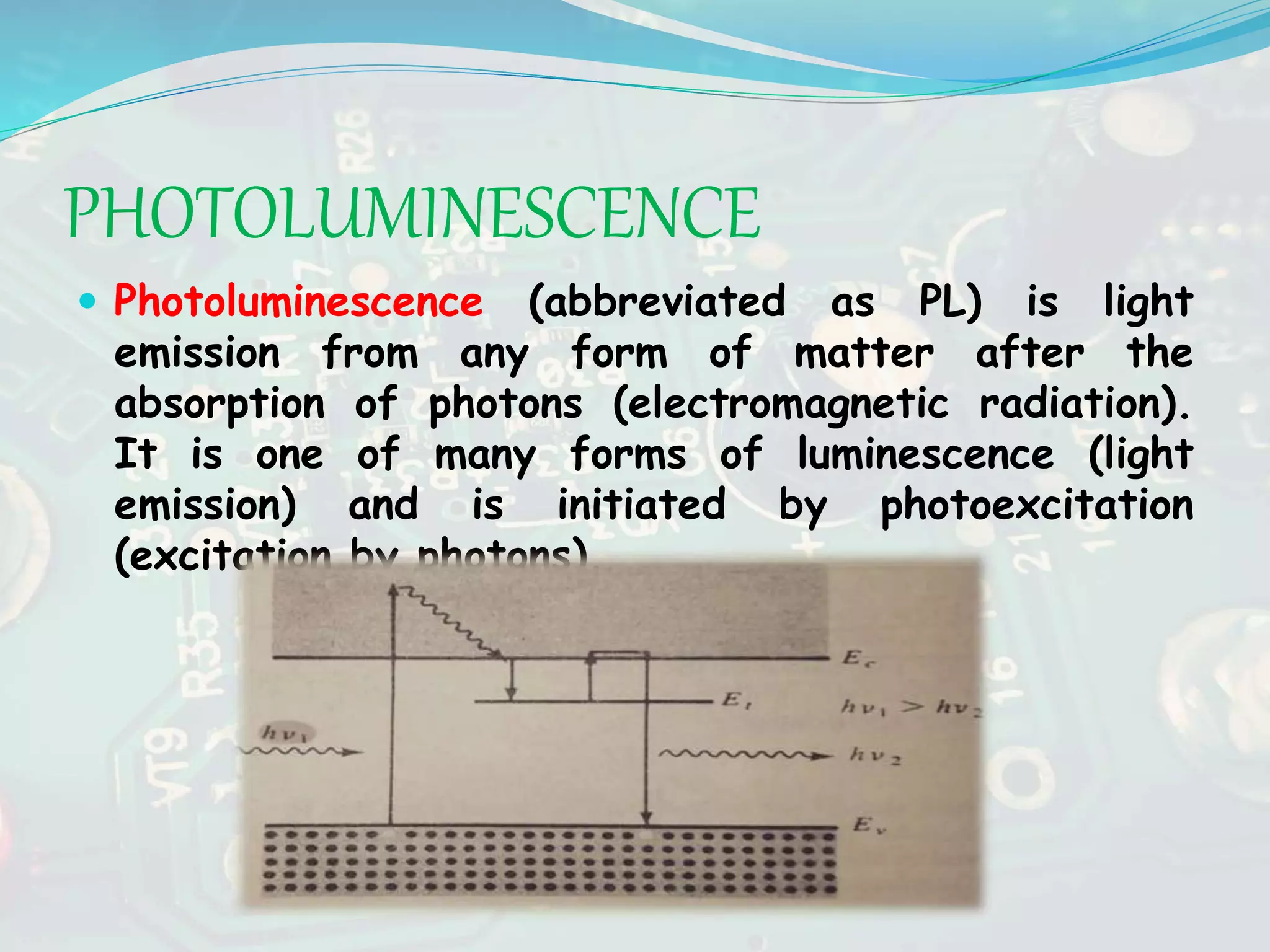
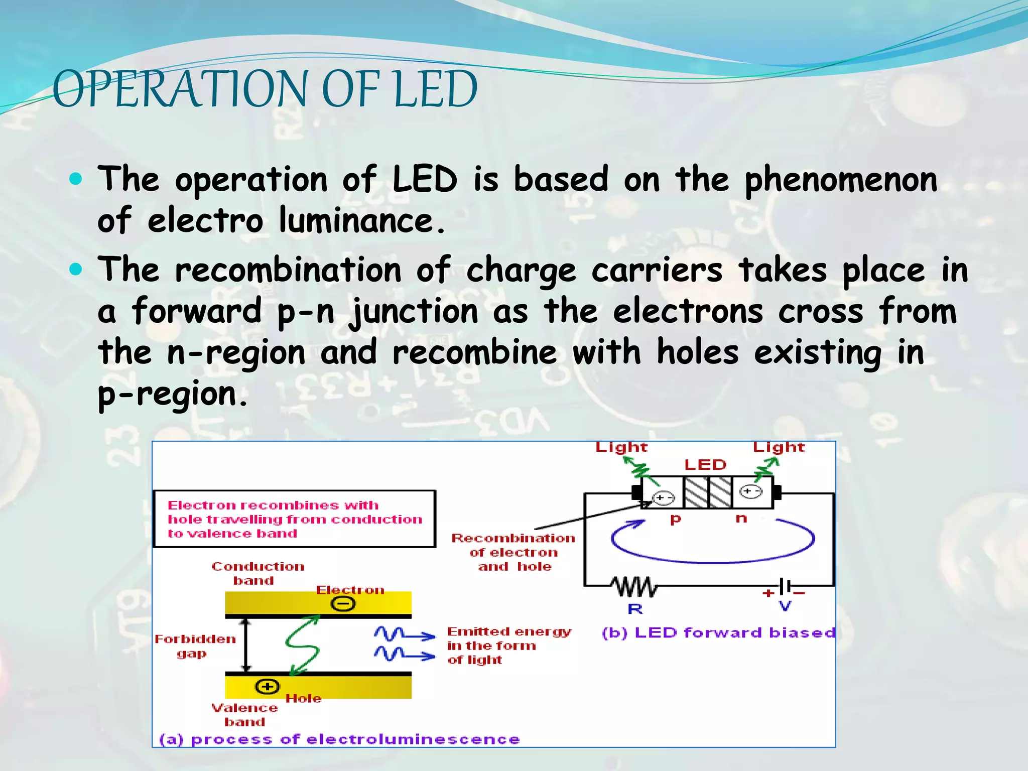
SEMINAR On fed
TOPIC-LUMINESCENCE
AVNEET SINGH LAL
EC-2
OPTICAL ABSORPTION
 A technique used for measuring the band
gap energy of a semiconductor is the
absorption of incident photons by the
materials.
 This experiment gives an accurate measure
of the band gap energy.
DIRECT & INDIRECT BANDGAP
SEMICONDUCTORS
 Those materials for which maximum of valence band and
minimum of conduction band lie for same value of k,
called DIRECT BANDGAP MATERIALS (i.e. satisfies
the condition of energy and momentum conservation).
For example: GaAs, InP, CdS..etc
 Those materials for which maximum of valence
band and minimum of conduction band do not occur
at same value of k, called INDIRECT BANDGAP
MATERIALS.
 For example: Si and Ge
BAND GAPS OF SOME COMMON
SEMICONDUCTORS RELATIVE TO THE OPTICAL
SPECTRUM
LUMINESCENCE
 The term 'luminescence' was introduced in 1888 by
Eilhard Wiedemann.
 Luminescence is emission of light by a substance
not resulting from heat; it is thus a form of cold-
body radiation.
 It can be caused by chemical reactions, electrical
energy and many other processes.
 Many of the semiconductors are well suited for
light emission, particularly the compound
semiconductors with direct band gaps.
 This overall category can be subdivided according
to the excitation mechanism.
TYPES OF LUMINESCENCE
a) PHOTOLUMINESCENCE
b) ELECTROLUMINESCENCE
c) CATHODOLUMINESCENCE
PHOTOLUMINESCENCE
 Photoluminescence (abbreviated as PL) is light
emission from any form of matter after the
absorption of photons (electromagnetic radiation).
It is one of many forms of luminescence (light
emission) and is initiated by photoexcitation
(excitation by photons).
 The emission of photons stops within
approximately 10-8 seconds after the
excitation is turned off. Such fast
luminescent processes are often referred to
as FLUORESCENCE.
 In some materials, emission continues for
periods up to seconds or minutes after the
excitation is removed. These slow processes
are called PHOSPHORESCENCE.
ELECTROLUMINESCENCE
 Electroluminescence (EL) is an optical phenomenon
and electrical phenomenon in which a material emits
light in response to the passage of an electric
current or to a strong electric field.
 This is distinct from black body light emission
resulting from heat (incandescence), from a
chemical reaction (chemiluminescence), sound
(sonoluminescence), or other mechanical action
(mechanoluminescence).
 There are many ways by which electrical energy
can be used to generate photon emission in a solid.
In LEDs an electric current causes the injection of
minority carriers into regions of the crystal where
they can recombine with majority carriers,
resulting in the emission of recombination radiation.
This effect is called as INJECTION
ELECTROLUMINESCENCE.
CATHODOLUMINESCENCE
 Cathodoluminescence is an optical and
electromagnetic phenomenon in which electrons
impacting on a luminescent material such as a
phosphor, cause the emission of photons which may
have wavelengths in the visible spectrum.
 The most common example of the excitation of
luminescent materials by energetic electrons is the
CATHODE-RAY TUBE(CRT).
 This light emitting tube is the basis of the
oscilloscope, television set, and other visual-display
systems.
 The basic principle of CRT is the selective
excitation of a phosphorescent screen by a beam
of energetic electrons within a vacuum tube.
crt
LED
ABOUT LED
 LED is an opto-electronic device which emits a narrow
bandwidth of visible or invisible light when its internal diode
junction is stimulated by a forward electric current or
voltage.
 LEDs convert electrical energy into light energy.
 The material used for LEDs are the direct Band Gap
Semiconductors which are made from group 3rd and group 5th
elements. For eg.- GaAs
OPERATION OF LED
 The operation of LED is based on the phenomenon
of electro luminance.
 The recombination of charge carriers takes place in
a forward p-n junction as the electrons cross from
the n-region and recombine with holes existing in
p-region.
APPLICATIONS
 Medical Instrumentation
 Bar Code Readers
 Fibre Optic Communication
 Digital Cameras
 Laptops
 Traffic Signals
 Rail
 Tower Lights
Solar cell
A structure that converts solar energy
directly to DC electric energy.
It supplies a voltage and a current to a
resistive load (light, battery, motor).
It is like a battery because it supplies DC
power.
It is different from a battery in the sense
that the voltage supplied by the cell
changes with changes in the resistance of
the load.
WHY SOLAR CELLS?
Low maintenance, long lasting sources of
energy
Non-polluting and silent sources of
electricity
Renewable and sustainable power, as a
means to reduce global warming.
APPLICATIONS
 Toys, watches, calculators
 Water pumping
 Water treatment
 Emergency power
 Portable power supplies
CONCLUSION
 The International Year of Light was officially launched on 19
January 2015 with a two-day Opening Ceremony at UNESCO
Headquarters in Paris.
 The International Year of Light and Light-based Technologies 2015
or International Year of Light 2015 (IYL 2015) was a United
Nations observance that aimed to raise awareness of the
achievements of light science and its applications, and its
importance to humankind.
REFERENCES
 SOLID STATE ELECTRONIC DEVICE (BEN
G. STREETMAN)
 LECTURE IN PHYSICS (FENNMAN)
 https://en.wikipedia.org
THE END
THANK YOU FOR YOUR
ATTENTION

Luminescence

  • 1.
  • 2.
    OPTICAL ABSORPTION  Atechnique used for measuring the band gap energy of a semiconductor is the absorption of incident photons by the materials.  This experiment gives an accurate measure of the band gap energy.
  • 3.
    DIRECT & INDIRECTBANDGAP SEMICONDUCTORS  Those materials for which maximum of valence band and minimum of conduction band lie for same value of k, called DIRECT BANDGAP MATERIALS (i.e. satisfies the condition of energy and momentum conservation). For example: GaAs, InP, CdS..etc
  • 4.
     Those materialsfor which maximum of valence band and minimum of conduction band do not occur at same value of k, called INDIRECT BANDGAP MATERIALS.  For example: Si and Ge
  • 5.
    BAND GAPS OFSOME COMMON SEMICONDUCTORS RELATIVE TO THE OPTICAL SPECTRUM
  • 6.
    LUMINESCENCE  The term'luminescence' was introduced in 1888 by Eilhard Wiedemann.  Luminescence is emission of light by a substance not resulting from heat; it is thus a form of cold- body radiation.  It can be caused by chemical reactions, electrical energy and many other processes.  Many of the semiconductors are well suited for light emission, particularly the compound semiconductors with direct band gaps.  This overall category can be subdivided according to the excitation mechanism.
  • 7.
    TYPES OF LUMINESCENCE a)PHOTOLUMINESCENCE b) ELECTROLUMINESCENCE c) CATHODOLUMINESCENCE
  • 8.
    PHOTOLUMINESCENCE  Photoluminescence (abbreviatedas PL) is light emission from any form of matter after the absorption of photons (electromagnetic radiation). It is one of many forms of luminescence (light emission) and is initiated by photoexcitation (excitation by photons).
  • 9.
     The emissionof photons stops within approximately 10-8 seconds after the excitation is turned off. Such fast luminescent processes are often referred to as FLUORESCENCE.  In some materials, emission continues for periods up to seconds or minutes after the excitation is removed. These slow processes are called PHOSPHORESCENCE.
  • 10.
    ELECTROLUMINESCENCE  Electroluminescence (EL)is an optical phenomenon and electrical phenomenon in which a material emits light in response to the passage of an electric current or to a strong electric field.  This is distinct from black body light emission resulting from heat (incandescence), from a chemical reaction (chemiluminescence), sound (sonoluminescence), or other mechanical action (mechanoluminescence).
  • 11.
     There aremany ways by which electrical energy can be used to generate photon emission in a solid. In LEDs an electric current causes the injection of minority carriers into regions of the crystal where they can recombine with majority carriers, resulting in the emission of recombination radiation. This effect is called as INJECTION ELECTROLUMINESCENCE.
  • 12.
    CATHODOLUMINESCENCE  Cathodoluminescence isan optical and electromagnetic phenomenon in which electrons impacting on a luminescent material such as a phosphor, cause the emission of photons which may have wavelengths in the visible spectrum.  The most common example of the excitation of luminescent materials by energetic electrons is the CATHODE-RAY TUBE(CRT).  This light emitting tube is the basis of the oscilloscope, television set, and other visual-display systems.  The basic principle of CRT is the selective excitation of a phosphorescent screen by a beam of energetic electrons within a vacuum tube.
  • 13.
  • 14.
  • 15.
    ABOUT LED  LEDis an opto-electronic device which emits a narrow bandwidth of visible or invisible light when its internal diode junction is stimulated by a forward electric current or voltage.  LEDs convert electrical energy into light energy.  The material used for LEDs are the direct Band Gap Semiconductors which are made from group 3rd and group 5th elements. For eg.- GaAs
  • 16.
    OPERATION OF LED The operation of LED is based on the phenomenon of electro luminance.  The recombination of charge carriers takes place in a forward p-n junction as the electrons cross from the n-region and recombine with holes existing in p-region.
  • 17.
    APPLICATIONS  Medical Instrumentation Bar Code Readers  Fibre Optic Communication  Digital Cameras  Laptops  Traffic Signals  Rail  Tower Lights
  • 18.
    Solar cell A structurethat converts solar energy directly to DC electric energy. It supplies a voltage and a current to a resistive load (light, battery, motor). It is like a battery because it supplies DC power. It is different from a battery in the sense that the voltage supplied by the cell changes with changes in the resistance of the load.
  • 19.
    WHY SOLAR CELLS? Lowmaintenance, long lasting sources of energy Non-polluting and silent sources of electricity Renewable and sustainable power, as a means to reduce global warming.
  • 20.
    APPLICATIONS  Toys, watches,calculators  Water pumping  Water treatment  Emergency power  Portable power supplies
  • 21.
    CONCLUSION  The InternationalYear of Light was officially launched on 19 January 2015 with a two-day Opening Ceremony at UNESCO Headquarters in Paris.  The International Year of Light and Light-based Technologies 2015 or International Year of Light 2015 (IYL 2015) was a United Nations observance that aimed to raise awareness of the achievements of light science and its applications, and its importance to humankind.
  • 22.
    REFERENCES  SOLID STATEELECTRONIC DEVICE (BEN G. STREETMAN)  LECTURE IN PHYSICS (FENNMAN)  https://en.wikipedia.org
  • 23.
    THE END THANK YOUFOR YOUR ATTENTION