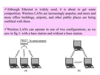
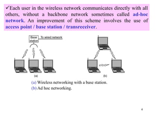
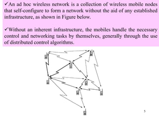
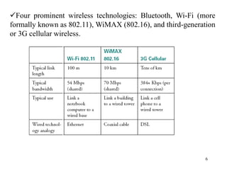
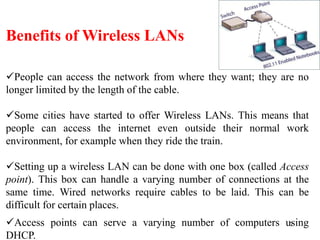
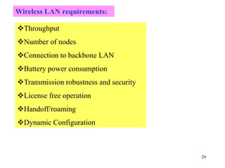
Wireless communication technologies like Wi-Fi, Bluetooth, and WiMAX allow devices to connect to networks without cables. Wireless LANs use radio signals to enable connectivity within small areas like buildings or campuses. They can operate with or without a central base station and provide mobility as users move around. However, wireless networks face challenges including interference between nearby transmissions and ensuring connectivity as users move between different base station signals. Standards use techniques like spread spectrum transmission and handoff processes to mitigate these issues.
Introduction by Dr. Md. Imdadul Islam, an expert from Jahangirnagar University, discusses mobile and wireless communications.
Wireless communication enjoys high demand with WLANs providing cable-free network access. WLANs can be deployed on-site and can function in two formats.
Ad hoc networks allow wireless mobile nodes to self-configure without infrastructure, using distributed algorithms for networking.
Key technologies like Bluetooth, Wi-Fi, WiMAX, and 3G cellular are discussed. Advantages include mobility and ease of setup.
WiMAX systems can utilize Relay Stations (RS) and Access Points (AP) to establish connections over wider areas.
Wireless networks face issues like collision management (Hidden Terminal Problem), multipath fading, and the need for efficient handoff.
Wireless LAN types include Infrared, Spread-Spectrum, Narrowband RF, Home RF, and Bluetooth technologies.
Bluetooth connects various devices in a piconet configuration and offers two connection types, focusing on real-time and data integrity.
The requirements for effective wireless LANs include throughput, node count, backbone connection, and mobility aspects.
Introduction to IEEE 802 activities in wired and wireless networking, detailing standards like 802.11 for WLANs and 802.15 for PANs.
Details on multiple 802.11 standards, capabilities, transmission rates, and enhancements related to Quality of Service (QoS).
IEEE 802.11 protocol stack structure, detailing the MAC and LLC sublayers, media access control, and data link functionalities.
Explains physical techniques used in wireless communication like PPM, FHSS, and DS spectrum spreading for improved transmission.
OFDM as an advanced modulation technique enhancing data rate and reliability by using multiple subcarriers.
The functionalities of the Data Link layer in IEEE 802.11, including frame formats, access methods, and collision avoidance.
CSMA/CA as a fundamental collision avoidance protocol in wireless LANs, including its operational mechanisms.
Bianchi's model describes packet transmission probabilities and handling of contention in wireless LAN saturation scenarios.
Comparative analysis of IEEE 802.11, 802.16 standards showing differences in functionality, range, and applications.
1
Dr. Md. ImdadulIslam
Professor, Department of Computer Science and Engineering
Jahangirnagar University
www. juniv.edu
Mobile and Wireless Communication System
PMSCS 658
Spring 2016
Department of Computer Science and Engineering
Jahangirnagar University
2.
2
Wireless communication isone of the fastest-growing technologies.
The demand for connecting devices without the use of cables is
increasing everywhere.
A WLAN provides wireless network communication over short
distances using radio or infrared signals instead of traditional network
cabling.
Wireless LANs provide high-speed data within a small region, e.g. a
campus or small building, as users move from place to place. Wireless
devices that access these LANs are typically stationary or moving at
pedestrian speeds.
Wireless LAN
3.
3
Although Ethernet iswidely used, it is about to get some
competition. Wireless LANs are increasingly popular, and more and
more office buildings, airports, and other public places are being
outfitted with them.
Wireless LANs can operate in one of two configurations, as we
saw in fig.1: with a base station and without a base station.
4.
4
Each user inthe wireless network communicates directly with all
others, without a backbone network sometimes called ad-hoc
network. An improvement of this scheme involves the use of
access point / base station / transreceiver.
(a) Wireless networking with a base station.
(b) Ad hoc networking.
5.
5
An ad hocwireless network is a collection of wireless mobile nodes
that self-configure to form a network without the aid of any established
infrastructure, as shown in Figure below.
Without an inherent infrastructure, the mobiles handle the necessary
control and networking tasks by themselves, generally through the use
of distributed control algorithms.
6.
6
Four prominent wirelesstechnologies: Bluetooth, Wi-Fi (more
formally known as 802.11), WiMAX (802.16), and third-generation
or 3G cellular wireless.
7.
7
Benefits of WirelessLANs
People can access the network from where they want; they are no
longer limited by the length of the cable.
Some cities have started to offer Wireless LANs. This means that
people can access the internet even outside their normal work
environment, for example when they ride the train.
Setting up a wireless LAN can be done with one box (called Access
point). This box can handle a varying number of connections at the
same time. Wired networks require cables to be laid. This can be
difficult for certain places.
Access points can serve a varying number of computers using
DHCP.
8.
8
There may beseveral RSs (Relay Stations) in the coverage area of
one WiMAX BS. Each RS can establish a communication link with its
BS and can serve several MSs in its signal coverage. In addition, a RS
can connect to multiple APs through wirelines (such as Ethernet,
Fiber, etc.), that is, this RS serves as the access network of these APs.
A dual-mode MS may connect to an AP or establish a
communication link with a RS. To save energy, a MS typically prefers
to turn on its 802.11b interface rather than its 802.16e interface.
Architecture of the LAN and MAN (WiFi- and WiMAX) integrated
network:
9.
9
Architecture of theLAN and MAN (WiFi- and WiMAX)
integrated network
Relay Station (RS)
AP Access Point
11
First Problem: Acomputer on Ethernet always listen to the ether
before transmitting. Only if the ether is idle does the computer begin
transmitting. With wireless LANs, that idea does not work so well.
12.
12
CSMA/CD Operation
C detectsa collision!
A detects a collision!
In wireless communication the
situation is cumbersome since
the received power is too small
compared to transmitted power.
13.
13
Suppose that computerA is transmitting to computer B (one way), but the radio
range of A is too short to reach computer C. If C wants to transmit to B it can listen to
the ether before starting, but the fact that it does not hear anything (since it is outside
the coverage of A) does not mean that its transmission will succeed. The 802.11
standard had to solve this problem (CSMA/CA).
14.
14
The problem wementioned here is called Hidden Terminal Problem
Consider the effect of RTS/CTS:
RTS alerts all stations within range of source (i.e., A) that exchange is
under way;
CTS alerts all stations within range of destination (i.e., B).
A and B can hear each other. B and
C can hear each other. But A and C
cannot hear each other.
When A is sending data to B, C
cannot sense this activity and
hence C is allowed to send data to
B at the same time. This will cause
a collision at B.
A B C
collision
15.
15
Second Problem: Multipathpropagation (Multipath fading)
due to presence of reflecting and refracting and scatterers hence
cause multiple versions of the signal arrive at the receiver.
With small variation of distance and time cause wide variation of
received signal called small scale fading experienced in a dense city.
16.
16
Handoff Region
BSi
Signal
strength due
toBSj
E
X1
Signal
strength due
to BSi
BSj
X3 X4 X2X5 Xth
MS
Pmin
Pi(x) Pj(x)
By looking at the variation of signal strength from either base station it is
possible to decide on the optimum area where handoff can take place.
Third Problem: Handoff is necessary like mobile communications
17.
17
Fourth Problem: Sometimes software is not aware of mobility. For
example many word processors have a list of printers that users can
choose to print a file. When the computer on which the word processor
runs is taken into a new environment, the built-in list of printer
becomes invalid.
18.
18
Wireless LAN technologiescan be classified into four types:
Infrared
Spread-spectrum
Narrowband RF
Home RF and Bluetooth.
Wireless LAN Technologies
19.
19
Each signal-covering cellin an infrared LAN is limited to one
room. Coverage is small, since the infrared rays cannot penetrate
through wall and other opaque obstacles.
Three alternative transmission techniques are used for infrared
data transmission: direct beam (point-to-point connection),
omnidirectional configuration consists of a single BS that is
normally used on ceilings, and diffused configuration (the
transmitter directs the signal to a diffused reflecting ceiling. The
signal is reflected in all directions from the ceiling. The receiver
then pick up the transmitted signal)
Infrared LANs
20.
20
Narrowband RF LANsuse very narrow bandwidth. Adjacent cells
use different frequency bands. The transmissions are encrypted to
prevent attacks.
Narrowband RF LANs
21.
21
There are severalControl Module (CM) to interface wireless LAN to
the backbone Ethernet (wired LAN).In previous figure each cell has
its own CM and connected by a switch to route traffic among them.
UM→ User Module
22.
22
Spread Spectrum LANs
Theidea behind spread spectrum is to spread the signal over a
wider frequency band than normal in such a way as to minimize
the impact of interference from other devices. Frequency hopping
is a spread spectrum technique that involves transmitting the signal
over a random sequence of frequencies, that is, first transmitting at
one frequency, then a second, then a third, and so on.
23.
23
Home RF isused to interconnect the various home electronic
devices such as, desktops, laptops and appliances. Home RF
supports data rates of about 2Mbps and has range of about 50m.
Home RF and Bluetooth
The basic Bluetooth network configuration, called a piconet, consists of a master
device and up to seven slave devices, as in Figure above. Any communication is
between the master and a slave; the slaves do not communicate directly with each
other. A Bluetooth device has a built-in short range radio transmitter.
24.
24
Bluetooth is awireless LAN technology designed to connect devices of different
functions such as telephone, notebooks, computers, cameras, printers etc.
Bluetooth defines two types of networks called: piconet and scatternet.
A piconet can have up to eight stations, one of which is called primary station, the
rest are called secondaries. All the secondary stations synchronize their clocks and
hopping sequence with the primary. Bluetooth uses frequency-hopping spread
spectrum (FHSS) in the physical layer to avoid interference from other devices or
network.
25.
25
Piconets can becombined to form scatternet where a secondary user of one piconet
acts as bridge to another piconet. The bridge secondary/slave acts as a primary in
receiving packets from the original primary of first piconet then deliver the packet to
secondaries of the second piconet.
Although a piconet can have maximum 7 secondaries , additional seconaries can be in
parked state. A seconadry in parked state is synchronized with the primary, but can not
take part in communication until it is removed from parked state to the active state.
27
Two types oflinks can be created between primary and secondary:
A synchronous connection-oriented (SCO) link is used when
avoiding latency (delay in data delivery) is more important than
integrity (error free delivery) for example real time audio. In this
case physical link is created primary and secondary by reserving
specific slots at regular intervals. The basic unit of connection is
two slots, one for each direction. If a packet is damaged it is never
retransmitted.
An asynchronous connectionless link (ACL) is used when data
integrity is more important than avoiding latency. In this type link if
payload encapsulated in the frame is lost/ corrupted, it is
retransmitted.
28.
28
Radio Layer
Baseband layer
L2CALlayer
Application Layer
Layers of Bluetooth
Radio layer is like physical layer of Internet. Uses FHSS, GFSK
modulation.
Baseband layer is like MAC sublayer uses TDMA slot as the physical
channel.
Logical Link Control and Adaption Protocol (L2CAP) is like LLC
sublayer.
29.
29
Wireless LAN requirements:
Throughput
Numberof nodes
Connection to backbone LAN
Battery power consumption
Transmission robustness and security
License free operation
Handoff/roaming
Dynamic Configuration
30.
30
The Institute ofElectrical and Electronics Engineers (IEEE,
read I-Triple-E) is a Professional association headquartered in
New York City that is dedicated to advancing technological
innovation and excellence. It has more than 400,000 members in
more than 160 countries, about 51.4% of whom reside in the
USA.
IEEE 802 Activities
31.
31
IEEE 802 Activities
Wired
802.3: Ethernet
802.17: Packet Ring (new)
Wireless
802.11: Wireless LAN
• Local Area Network
802.15: Wireless PAN
– Personal Area Network (e.g. BluetoothTM)
802.16: WirelessMANTM
– Metropolitan Area Networks
32.
32
There are severalspecifications in the 802.11 family:
IEEE has defined the specifications for WLAN, called IEEE
802.11, which covers physical and data-link layer. Public
uses the term WiFi (Wireless Fidelity) for WLAN.
802.11 — applies to wireless LANs and provides 1 or 2 Mbps
transmission in the 2.4 GHz band using either frequency hopping
spread spectrum (FHSS) which uses 2 or 4 level FSK or direct
sequence spread spectrum (DSSS) which uses BPSK or QPSK.
802.11 Infrared uses infrared light in the range of 800 to 950 nm. The
modulation technique is called PPM (Pulse Position Modulation).
33.
33
802.11a— an extensionto 802.11 that applies to wireless LANs and
provides up to 54-Mbps in the 5GHz band. 802.11a uses an orthogonal
frequency division multiplexing (OFDM) scheme rather
than FHSH or DSSS. Here PSK and QAM modulation scheme is used.
802.11b (also referred to as 802.11 High Rate or Wi-Fi) — an extension
to 802.11 that applies to wireless LANS and provides 11 Mbps
transmission (with a fallback to 5.5, 2 and 1-Mbps) in the 2.4 GHz band.
34.
34
802.11e — awireless draft standard that defines the Quality of Service (QoS)
support for LANs, and is an enhancement to the 802.11a and 802.11b wireless LAN
(WLAN) specifications. 802.11e adds QoS features and multimedia support to the
existing IEEE 802.11b and IEEE 802.11a wireless standards, while maintaining full
backward compatibility with these standards.
802.11g — applies to wireless LANs and is used for transmission over short
distances at up to 54-Mbps in the 2.4 GHz bands.
802.11n — 802.11n builds upon previous 802.11 standards by adding multiple-
input multiple-output (MIMO). The additional transmitter and receiver antennas
allow for increased data throughput through spatial multiplexing and increased
range by exploiting the spatial diversity through coding schemes like Alamouti
coding. The real speed would be 100 Mbit/s (even 250 Mbit/s in PHY level), and so
up to 4-5 times faster than 802.11g.
35.
35
802.11ac — 802.11acbuilds upon previous 802.11 standards, particularly the
802.11n standard, to deliver data rates of 433Mbps per spatial stream, or 1.3Gbps
in a three-antenna (three stream) design. The 802.11ac specification operates only
in the 5 GHz frequency range and features support for wider channels (80MHz and
160MHz) and beamforming capabilities by default to help achieve its higher
wireless speeds.
802.11ac Wave 2 — 802.11ac Wave 2 is an update for the original 802.11ac spec
that uses MU-MIMO technology and other advancements to help increase
theoretical maximum wireless speeds for the spec to 6.93 Gbps.
802.11ad— 802.11ad is a wireless specification under development that will
operate in the 60GHz frequency band and offer much higher transfer rates than
previous 802.11 specs, with a theoretical maximum transfer rate of up to 7Gbps
(Gigabits per second).
36.
36
802.11r - 802.11r,also called Fast Basic Service Set (BSS)
Transition, supports VoWi-Fi handoff between access points to
enable VoIP roaming on a Wi-Fi network
with 802.1X authentication.
802.1X — Not to be confused with 802.11x (which is the term used
to describe the family of 802.11 standards) 802.1X is an IEEE
standard for port-based Network Access Control that allows network
administrators to restricted use of IEEE 802 LAN service access
points to secure communication between authenticated and
authorized devices.
37.
37
A partial viewof the 802.11 protocol stack is given in fig. below. The physical layer
corresponds to the OSI physical layer fairly well, but the data link layer in all the 802
protocols is split into two or more sublayers.
In 802.11, the MAC (Medium Access Control) sublayer determines how the channel
is allocated, that is, who gets to transmit next. Above it is the LLC (Logical Link
Control) sublayer, whose job it is to hide the differences between the different 802
variants and make them indistinguishable as far as the network layer is concerned.
The 802.11 Protocol Stack
39
Infrared with PPMscheme
FHSS (Frequency Hopping Spread Spectrum)
DSSS (Direct Sequence Spread Spectrum)
OFDM (Orthogonal Frequency Division Multiplexing)
HR-DSSS (High Rate DSSS)
The 802.11 Physical Layer
40.
40
The infrared optionnever gained market support.
Infrared at 1 Mbps and 2Mbps operates at wavelength between
850 and 950nm.
Infrared with PPM scheme
41.
41
DS Spectrum SpreadingTechnique
Spread spectrum involves the
use of a much wider BW than
actually necessary to support a
given data rate. The result of
using wider BW is to minimize
interference and drastically
reduce BER. It operates in
2.4GHz band at data rate of
1Mbps and 2Mbps.
42.
42
DS spectrum spreadingis accomplished by means of a two-input
exclusive-OR gate where A is low-speed NRZ data and B is high-speed
PN sequence.
A
B
CNRZ Data
PN code
A
B
C
DS spreading
BABAC
43.
43
DS spectrum dispreadingis a process of data recovery from the
composite spread-spectrum signal. This is accomplished by means of
another exclusive-OR gate where the composite data C is applied to one
input and identical PN sequence is applied to second input. The output Y
is a decomposed signal which is the original NRZ data.
C
B
A
DS De-spreading
C
B
Y = A
BCBCY
45
In case ofFHSP, spread spectrum is achieved by frequently jumping
from one carrier frequency to another; thus if there is interference or
performance degradation at a given frequency, it only affects a small
fraction of transmission.
The amount of time spent at each frequency, the dwell time, is an
adjustable parameter but must be less than 400 ms.
Operates at 2.4 GHz band at data rate of 1Mbps and 2Mbps
Frequency Hopping Spread Spectrum
46.
46
Orthogonal Frequency DivisionMultiplexing (OFDM) is a multi-carrier
modulation scheme that transmits data over a number of orthogonal subcarriers. A
conventional transmission uses only a single carrier modulated with all the data to be
sent.
OFDM breaks the data to be sent into small chunks, allocating each sub-data
stream to a sub-carrier and the data is sent in parallel orthogonal sub-carriers. As
illustrated in Figure 1, this can be compared with a transport company utilizing
several smaller trucks (multi-carrier) instead of one large truck (single carrier).
Fig.1 Single carrier vs. multi-carrier transmission
Orthogonal Frequency Division Multiplexing
IEEE 802.11a and 802.11g
48
1. It elongatesthe symbol period so that the signal is more robust
against intersymbol interference caused by channel dispersions
and multipath interference.
2. It divides the entire frequency band into narrow bands so that it
is less sensitive to wide-band impulse noise and fast channel
fades.
3. Splitting the channel into narrowband channels enables
significant simplification of equalizer design in multipath
environments.
OFDM offers many advantages over single-carrier modulations:
49.
49
4. Different modulationformats and data rates can be used on
different subcarriers depending on the noise level of individual
subbands (the symbol periods are kept the same). In serial
transmission, certain types of noise (such as timevarying tone
interference) may cause an entire system to fail; the parallel
OFDM system can avoid this problem by adaptively reducing
the data rate of the affected subbands or dropping them.
5. OFDM can be implemented digitally using an inverse discrete
Fourier transform and discrete Fourier transform (IDFT/DFT)
pair (via the efficient fast algorithm IFFT/FFT pair), which
greatly reduces the system complexity.
50.
50
A baseband OFDMtransmission model is shown in Figure 3. It basically consists of
a transmitter (modulator, multiplexer and transmitter), the wireless channel, and a
receiver (demodulator).
tfj
e 02
U
U
Tm
mT
)1(
...m
Nc
a 1
ˆ
S/P
Σ x(t)
x0(t)
x1(t)
xNc-1(t)
Channel
r(t)
m
N
mm
C
aaa 110 ,...,,
m
a0
m
a1
m
Nca 1
tfj
e 12
tfj Nc
e 12
tfj
e 02
tfj
e 12
tfj Nc
e 12
…
…
…
U
U
Tm
mT
)1(
...
U
U
Tm
mT
)1(
...
m
a0ˆ
m
a1ˆ
Fig.3
51.
51
S/P IDFT
0
0
…
…
A0
A1
AN-1
P/S
m
N
mm
C
aaa 110,...,,
m
a0
m
a1
m
Nca 1
…
…
…
…
…
…
…
…
…
D/A Channel
DFT
A/D P/S
r0
r1
rN-1
…
…
…
…
…
… …
…
…
…
…m
a0ˆ
m
a1ˆ
m
a0ˆ
m
NC
a 1ˆ
Useless
P/S
m
N
mm
C
aaa 110 ˆ,...,ˆ,ˆ
Fig.4 Transmitter and receiver by using FFT processing
r(t)
x(t)
52.
52
The Data Linklayer of IEEE 802.11 has two parts: LLC and
MAC sublayer. This layer provides several key functionalities:
reliable data delivery, media access control and security features.
Data Link Layer of IEEE 802.11
53.
53
The frame control(FC) field provides information on the type of
frame has 11 subfields.
The first of these is the Protocol version, two bits representing the
protocol version. Currently used protocol version is zero. Other values
are reserved for future use.
Then come the Type of 2 bits (data, control, or management); where
‘Type of information: management (00), control (01), or data (10)’.
The frame format of IEEE 802.11
54.
54
A node wishingto send data initiates the process by sending a
Request to Send frame (RTS). The destination node replies with a
Clear To Send frame (CTS). Subtype fields indicates like the
following category.
Values of subfields in control frames
55.
55
The IEEE 802.11addressing mechanism specifies four cases, defined by the
value of the two flags in the FC field, To DS and From DS. Each flag can be
either 0 or 1, resulting in four different situations. The interpretation of the four
addresses (address 1 to address 4) in the MAC frame depends on the value of these
flags, as shown in Table below.
56.
56
The MF bitmeans that more fragments will follow. The Retry bit
marks a retransmission of a frame sent earlier. The Power
management bit is used by the base station to put the receiver into
sleep state or take it out of sleep state. The More bit indicates that
the sender has additional frames for the receiver.
The W bit specifies that the frame body has been encrypted using
the WEP (Wired Equivalent Privacy) algorithm. Finally, the O bit
tells the receiver that a sequence of frames with this bit on must be
processed strictly in order.
57.
57
Duration field refersto the time allotted for the successful transmission of the
frame. How long the frame and its ack will occupy the channel.
The address field denotes the 6-byte (MAC address of 48 bits) source and
destination address fields. The source and destination addresses are obviously
needed and the other two addresses are used for source and destination BSs for
intercell traffic. Since frame may enter or leave a cell via a BS.
The sequence control (SC) field consists of 4 bits reserved for fragmentation
and reassembly and 12 bits for a sequence number of frames between a particular
Tx and Rx.
The frame body/Data contains a MAC service data unit or control information.
The CRC field is used for error detection.
58.
58
Standard 802.11 typicallyuses the carrier Sense Multiple Access
with collision avoidance (CSMA/CA) method.
Carrier sense (CS) means: hardware capable of sensing whether
transmission taking place in vicinity (for cognitive radio).
With this method, each user listens for traffic coming from other
users (a node can sense a traffic channel like combination of
carrier and TS) and transmits data if the channel is idle.
If the channel is busy, the user waits until the channel becomes
idle. The user then transmits data after a random back-off time.
IEEE 802.11 at MAC sublayer uses CSMA/CA
as the access method.
59.
59
The wireless LANsystem cannot detect collisions because the
power of the transmitting device is much stronger than the receiver’s
power.
In this situation collision detection is not practical, it makes sense to
try to devise a system that can help prevent collisions. Thus the CA is
CSMA/CA refers to ‘collision avoidance’.
When a device detects that the transmission media is idle, the
device must wait for a specific time before it can contend for access
to the media. This specific time is called interframe spacing (IFS)
time.
The IFS time can also be used for prioritizing transmissions. If a
device is given a smaller IFS , then it has more chances of gaining
access to the transmission media.
Carrier Sense Multiple Access/ Collision
Avoidance (CSMA/CA)
60.
60
If the senderdoes not receive an ACK then the device assumes
that a collision has occurred. Sender usually uses binary
exponential backoff.
61.
61
To reduce thepacket dropping probability or to enhance throughput of wireless LAN
exponential binary backoff algorithm is widely used. The access method of MAC
protocol of IEEE 802.11 based on exponential binary backoff algorithm can be
explained with the following steps.
Step: 1
The transmitting node first senses the status of the channel. If the channel is found
busy then the Tx node continues to monitor the channel.
Step:2
If the channel is found idle for a fixed duration know as DIFS (Distributed Inter-
frame Space), the Tx chooses a random number according to the binary exponential
back off algorithm. The random number is used as a back off timer.
Distributed Binary Exponential Backoff Algorithm
62.
62
Step:3
Time immediately afterthe DIFS (Distributed Inter-frame Space) is
slotted known as idle slots where the duration of a slot is
considered as the sum of the time required to sense a station and to
switch the Tx from sensing / listening mode to transmitting mode.
Step:4
Elapsing of each idle slot the back off timer is decreased by one. If
the channel is found busy before the back off timer reaches to zero
then repeat the steps 1 to 3. The transmission of data from begins
only if the back off timer reaches to zero.
63.
63
Step:5
To determine whethera data frame transmission is successful,
after its completion, a positive acknowledgement (ACK) is
transmitted by the receiver. ACK is transmitted after a short
interframe space (SIFS) period upon receiving the entire data
frame successfully.
If ACK is not detected within an SIFS period after the
completion of the data frame transmission, the transmission is
assumed to be unsuccessful, and a retransmission is required.
64.
64
The main contributionof Bianchi’s model is the analytical calculation of
saturation throughput in a closed-form expression. The model also calculates the
probability of a packet transmission failure due to collision.
Bianchi uses a two-dimensional Markov chain of m + 1 backoff stages in which
each stage represents the backoff time counter of a node, see Figure below.
A transition takes place upon collision and successful transmission. If collision
takes place probability state moves to to a “higher” stage e.g., from stage i-1 to
stage i. When a successful transmission occurs then state goes to the lowest stage
i.e., stage 0.
Each state of this bidimensional Markov process is represented by {s(t), b(t)},
where b(t) is the stochastic process representing the backoff time counter for a
given station and s(t) is the stochastic process representing the backoff stage (0, 1, ·
· · ,m) of the station at time t.
Bianchi Model
66
Carrier Sense MultipleAccess/ Collision
Detection (CSMA/CD)
A collision detection mechanism compares the amount of energy
on the media after a packet is transmitted. If the value is greater than
the the energy used by the transmitting device, then a collision has
occurred. If there is no difference the two measured values, then a
collision has not occurred.
67.
67
IEEE 802.11 isa standard for a wireless LAN; 802.16 is a standard
for wireless WAN or MAN. It is broadband wireless system called
WiMAX (Worldwide Interoperability for Microwave Access).
802.11 provides connectionless communication where as 802.16
provides connection oriented service.
The IEEE 802.16 group was formed in 1998 to develop an air-
interface standard for Broadband Wireless Access (BWA) and to
support the development and deployment of wireless metropolitan area
networks
A later version of IEEE 802.16 created two new standards called
IEEE 802.16d for fixed WiMAX and IEEE 802.16e for mobile
WiMAX .
IEEE 802.16
The IEEE 802.16data link layer layer is composed of three sub-layers
Service Specific Convergence Sub-layer (CS), MAC Common Part Sub-
layer (CPS) and the Security Sub-layer. Each sub-layer has a specific
function to perform.
The 802.16 Protocol Stack
The 802.16 protocol stack
72.
The Service-Specific ConvergenceSub-layer (CS) provides any
transformation or mapping of external network data, received through
the CS service access point (SAP), into MAC SDUs received by the
MAC Common Part Sub-layer (CPS) through the MAC SAP. Its
function is to interface to the network layer such that it integrate with
both datagram protocols (PPP, IP, and Ethernet) and ATM.
73.
73
A complication hereis that 802.16 was designed to integrate
seamlessly with both datagram protocols (e.g., PPP, IP, and Ethernet)
and ATM. The problem is that packet protocols are connectionless
and ATM is connection oriented. This means that every ATM
connection has to map onto an 802.16 connection, in principle a
straightforward matter. But onto which 802.16 connection should an
incoming IP packet be mapped? That problem is dealt with in this
sublayer.
The core part of the IEEE 802.16 MAC is the MAC CPS, as it
provides the core MAC functionality of system access bandwidth
allocation, connection establishment, and connection maintenance.
The MAC also contains a separate security Sublayer providing
authentication, secure key exchange, and encryption.
74.
74
The 802.16 PhysicalLayer
Broadband Wireless
signal strength in the millimeter band falls off sharply with distance from the base
station, the signal-to-noise ratio also drops with distance from the base station. For
this reason, 802.16 employs three different modulation schemes, depending on how
far the subscriber station is from the base station.
75.
75
The IEEE 802.16estandard enables optimization of each SS’s data
rate by allowing the BS to set the modulation schemes on a link-by-link
basis. An SS close to the BS could use a high modulation scheme,
thereby giving the system more capacity.
In contrast, a weak signal from a more remote subscriber might only
permit the use of a lower modulation scheme to maintain the connection
quality and link stability. Modulation coding schemes (MCSs) is given
below
77
Figure 4-34. (a)A generic frame. (b) A bandwidth request frame.
The 802.16 Frame Structure
All MAC frames begin with a generic header. The header is
followed by an optional payload and an optional checksum (CRC),
as illustrated in
78.
78
The EC bittells whether the payload is encrypted.
The Type field identifies the frame type, mostly telling whether
packing and fragmentation are present.
The CI field indicates the presence or absence of the final
checksum.
The EK field tells which of the encryption keys is being used (if
any). The Length field gives the complete length of the frame,
including the header. The Connection identifier tells which
connection this frame belongs to.
Finally, the HeaderCRC field is a checksum over the header only,
using the polynomial x8 + x2 + x + 1
79.
79
Comparisons among WLAN,WMAN, WWAN
Feature IEEE 802.11b
WLANs
IEEE 802.16
WMANs
GSM WWANs
Range Few hundred meters Several Km Few tens of Km
Frequency 2.4 GHz ISM band 10-66 GHz 900 or 1800 MHz
Physical Layer CCK, BPSK, QPSK QAM-64, QAM-16,
QPSK
GMSK
Maximum Data
Rate
11 Mbps 60-180 Mbps 9.6 Kbps/user
Medium Access CSMA/CA TDM/TDMA FDD/TDMA
QoS Support DCF - No
PCF - Yes
Yes Yes
Connectivity DCF- Connectionless
PCF - Connection
Connection oriented Connection
Oriented
Typical
Applications
Web browsing, e-
mail
Multimedia, digital
TV broadcasting
Voice