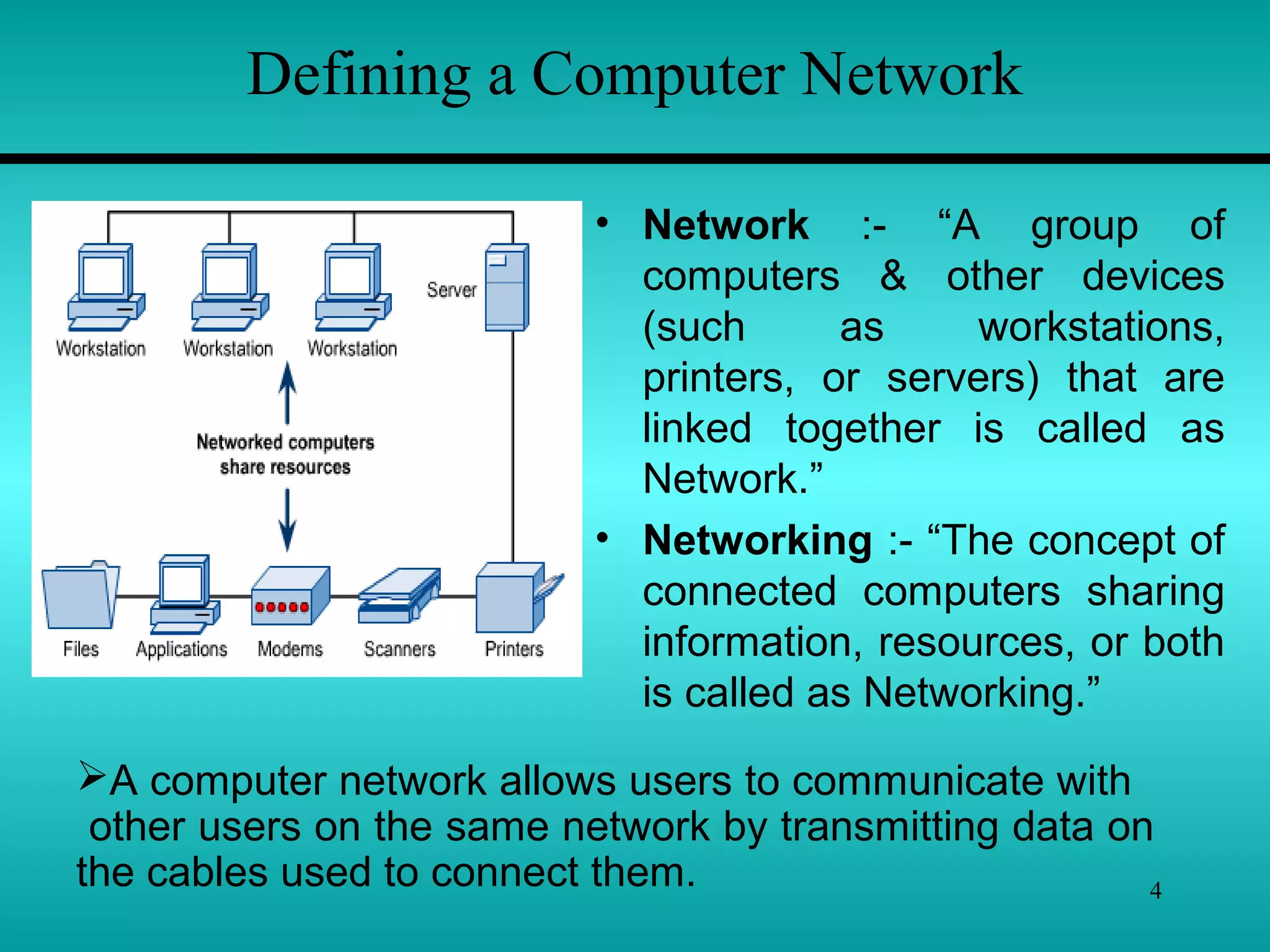
Introduction to Networking
1
By Vikas Jagtap
vikas27jagtap@gmail.com
2
Chapter 1
Introduction to Networking
Introduction to PC Networking
1.1 – Hardware Architecture: -
Topologies, Media, Devices
1.2 – Transmission Techniques: -
Twisted Pair, Coaxial Cable,
Fiber Optics, Wireless Transmission
1.3 – Switching: -
Circuit Switching, Message Switching,
Packet Switching.
3
Introduction to PC Networking
4
Defining a Computer Network
• Network :- “A group of
computers & other devices
(such as workstations,
printers, or servers) that are
linked together is called as
Network.”
• Networking :- “The concept of
connected computers sharing
information, resources, or both
is called as Networking.”
A computer network allows users to communicate with
other users on the same network by transmitting data on
the cables used to connect them.
5
File, Print, and Application Services
• All network operating
systems offer file and
print services.
• Sharing information,
collaborating on projects,
and providing access to
input and output devices
are common services of
computer networks.
6
Directory and Name Services
• To enable users and
systems on the network to
find the services they
require, computer networks
make use of directories and
name services.
7
Directory and Name Services
• Directory and name
services make a network
easier to use.
• After the initial setup of the
directory or name service,
this translation takes place
transparently.
• In addition to their ease of
use, they also make the
network more flexible.
8
Types of Networks
 Peer-to-Peer Networks
 Client/Server Networks
 Local-Area Networks (LANs)
 Wide-Area Networks (WANs)
9
Peer-to-Peer Networks
• In a peer-to-peer network,
the networked computers
act as equal partners, or
peers, to each other.
• As peers, each computer
can take on the client
function or the server
function alternately.
10
Client/Server Networks
• In a client/server network
arrangement, network
services are located in a
dedicated computer whose
only function is to respond to
the requests of clients.
• The server contains the file,
print, application, security,
and other services in a
central computer that is
continuously available to
respond to client requests.
11
Local-Area Networks (LANs)
• A local-area network (LAN)
can connect many
computers in a relatively
small geographical area
such as a home, an office,
or a campus.
• They are widely used to
connect personal
computers & workstations in
company offices & factories
to share devices(resources)
such as printers &
exchange information.
12
Wide-Area Networks (WANs)
• A WAN, Spans a large
geographical area, often a country
or continent.
• It contains a collection of Machines
intended for running user
programs. We will follow traditional
usage & call these machines
hosts.The hosts are connected by
a communication subnet or just
subnet for short.
• The hosts are owned by the
customer, whereas the subnet is
typically owned & operated by a
telephone company or Internet
Service Provider.
•The job of the subnet is to carry message from host to host, just as
the telephone system carries words from speaker to listener.
13
Wide-Area Networks (WANs)
• Connections across WAN lines
may be temporary or
permanent.
• Telephone or dialup lines, might
make a temporary connection to
a remote network from a
computer in a home or small
office.
• In both temporary and
permanent cases, computers
that connect over wide area
circuits must use a modem or
channel service unit/data
service unit (CSU/DSU) at each
end of the connection.
14
Network Topologies
“The network topology defines the way in which computers,
printers, and other devices are connected. A network
topology describes the layout of the wire and devices as well
as the paths used by data transmissions.”
15
Bus Topology
 The Bus is a Passive Topology becoz it does not amplify or
regenerate the signal.
 When one computer sends a signal up(& down) the wire, all
the computers on the network receive the information, but
only one (which matches the address) accepts the
information. The rest discard the message.
 Only one computer at a time can send a message; therefore
the number of computers attached to a bus network can
significantly affect the speed of the network.
 A computer must wait until the bus is free before it can
transmit.
 The Bus topology is often used
when a network installation is
small, simple or temporary.
16
Bus Topology
 Another important issue in bus networks is ‘Termination’.
 The electrical signal from a transmitting computer is free
to travel the entire length of the cable. Without termination,
when the signal reaches the end of the wire, it bounces back
& travels back up the wire.
 When the signal echoes back & forth along an
unterminated bus, it is called ‘ringing’.
 To stop the signals from ringing, you attach ‘terminator’ at
either end of the segment.
 Terminator absorb the electrical energy & stop the
reflections.
 Cables can’t be left unterminated in a bus network.
17
Bus Topology
1) The bus is simple, reliable in very small networks,
easy to use, & easy to understand.
2) The bus requires the least amount of cable to connect
the computers together & is therefore less expensive
than other cabling arrangement.
3) It is easy to extend a bus. Two cables can be joined into
one longer cable with a BNC(British Naval Connector)
barrel connector, making a longer cable & allowing
computers to join the network.
4) A repeater can also be used to extend a bus; a repeater
boosts the signal & allow it to travel a longer distance.
 Advantages of the Bus –
18
Bus Topology
 Disadvantages of the Bus –
1) Heavy network traffic can slow a bus considerably.
Because any computer can transmit at any time, &
computers on most bus networks do not co-ordinate
with each other to reserve times to transmit, a bus
network with a lot of computers can spend a lot of its
bandwidth(capacity for transmitting information) with
computers interrupting each other instead of
communicating.
2) Each barrel connector weakens the electrical signal, &
too many may prevent the signal from being correctly
received all along the bus.
3) A cable break or loose connector will also cause
reflections & bring down the whole network, causing all
network activity to stop.
19
Star Topology
 In a star topology all the cables run from
the computer to a central location, where
they are all connected by a device called
‘Hub’.
 Stars are used in concentrated networks, where the endpoints
are directly reachable from a central location; when network
expansion is expected; & when the greater reliability of a star
topology is needed.
 Each computer on a star network communicates with a central
hub that resends the message either to all the computers(in a
broadcast star network) or only to the destination computer(in a
switched star network).
 The hub in a broadcast star network can be active or passive.
20
Star Topology
 An active hub regenerates the electrical
signals & send it to all the computers
connected to it.
 A passive hub, does not amplify or
regenerate the signal.
An active hub requires electrical power to
run, whereas passive hub does not.
 You can use several types of cable to
implement a star network.
 A star network cab be expanded by
connecting another star hub to main hub.
This is called a hybrid star network.
21
Star Topology
 Advantages of the Star –
1) It is easy to modify & add new computers to a star
network without disturbing the rest of the network.
2) The center of a star network is a good place to diagnose
network faults. Some hubs that have microprocessor
are called intelligent hubs. They provide centralized
monitoring & management of the network.
3) Single computer failures do not necessarily bring down
the whole star network. The hub can detect a network
fault & isolate the offending computer or network cable
& allow the rest of the network to continue operating.
4) You can use several cable types in the same network
with a hub that can accommodate(find a room for)
multiple cable types.
22
Star Topology
 Disadvantages of the Star –
1) If a central hub fails, the whole network fails to operate.
2) It costs more to cable a star network because all
network cables must be pulled to one central point,
requiring more cable than other networking topologies.
23
Ring Topology
 In a ring topology each computer is
connected to the next computer, with
the last one connected to the first.
 Rings are used in high-performance
networks, networks requiring that
bandwidth be reserved for time –
sensitive features such as video &
audio or when performance is
needed when a large no. of clients
access the network.
 Every computer is connected to the next computer in the ring, &
each retransmits what it receives from the previous computer. The
message flow around the ring in one direction.
Since each computer transmits what it receives, a ring is an
‘active’ network & is not subject to the signal loss problems. There
is no termination b’coz there is no end of the ring.
24
Ring Topology
 Some ring networks do ‘token
passing’. A short message called a
‘token’ is passed around the ring
until a computer wishes to send
information to another computer.
 Each computer in sequence
receives the token & the information
& passes them to the next computer
until either the electronic address
matches the address of a computer
or the token returns to its origin.
 The receiving computer returns a message to the originator indicating that
the message has been received. The sending computer then creates
another token & places it on the network, allowing another station to capture
the token & begin transmitting. The token circulates until a station is ready
to send & capture the token.
25
Single ring – All the devices
on the network share a single
cable
Dual ring – The dual ring
topology allows data to be sent
in both directions although only
one ring is used at a time.
Ring Topology
26
Ring Topology
 Disadvantages of the Ring –
1) Failure of one computer on the ring can affect the
whole network.
2) It is difficult to troubleshoot a ring network.
3) Adding or removing computers break up the network
 Advantages of the Ring –
1) Because every computer is given equal access to the token,
no one computer can get control of whole the network.
2) The fair sharing of the network allows the network to degrade
gracefully (continue to function in a useful, if slower, manner
rather than fail once capacity is exceeded) as more users are
added.
27
Mesh Topology
 The mesh topology connects all
devices (nodes) to each other
for redundancy and fault
tolerance.
 It is used in WANs to
interconnect LANs and for
mission critical networks like
those used by governments.
 In mesh, every device is connected to every other device, this
increase fault tolerance but involves extra work.
 If media break, data transfer can take alternative routes.
Caballing is complicated here.
 Implementing the mesh topology is expensive and difficult.
28
Mesh Topology
 Advantages & Disadvantages of the Mesh –
The major advantage of the mesh topology is fault tolerance.
Other advantages include guaranteed communication channel
capacity & the fact that mesh networks are relatively easy to
troubleshoot.
Disadvantages include the difficulty of installation and
reconfiguration, as well as the cost of maintaining redundant
links.
29
Networking Media
 “Networking media can be defined simply as the
means by which signals (data) are sent from one computer
to another (either by cable or wireless means).”
 Different media have different properties & are most
effectively used in different environment for different
purpose.
 In computer networking, the medium affects nearly
every aspect of communication.
 Most important, it determines how quickly & to whom a
computer can talk & how expensive the process is.
30
Networking Media
 Copper -
 The most common network medium is ‘Copper’. Engineers
have become very good at sending electrical signals over
copper wires & detecting them with a great deal of
fidelity(accuracy) at other end.
 Fidelity is how precisely the signal that is received
corresponds to the signal that was sent.
 It is electricity, not photons or radio waves, that flows through
the logic of personal computers, so it is convenient to send that
electricity out over copper wires to be detected by other
computers.
31
Networking Media
 Glass -
 Photons are the basic particles of light. Photons are not
affected by interference from electrical devices or radio waves,
which is a major concern in high-speed copper network.
 Fiber-optics is a networking technology developed to exploit
the communications medium of light in long strands of glass.
 Light can travel for several miles in the less expensive multi-
mode fiber-optic cable without signal loss.
 Fiber-optics is used mainly in environments where copper will
not work & where the faster speed is really needed for instance,
a machinery shop.
32
Networking Media
 Air -
 Both fiber-optics & copper cabling have the drawback that
you need a cable to connect the computer.
 Infrared provides an effective solution for temporary or hard-
to-cable environments, or where computers (such as laptops)
are moved around a lot.
 Infrared is a line-of-sight technology. The photons will not go
through walls, which limits the usefulness of infrared in office
environment.
 Infrared is not a very high-speed network when compared to
copper & fiber-optic network. Infrared adapters at speeds
ranging from .3MBPS to 4MBPS
33
Networking Media
 Radio -
 Another through the air method is via radio. Engineers have
been sending information over electromagnetic waves for
almost as long as they have over copper wires.
 Radio waves will go through walls. Radio waves will also
reach places it is difficult to get a network cable to.
 Radio links can connect computers without regard to walls or
line of sight.
 Radio is also immune (secure) to rain & snow, unlike external
infrared installation.
34
Transmission Techniques
“The Physical path through which computers
send & receive electronic signals is called the
transmission media.”
Two type of Transmission Techniques Follows –
1) Cable Media
2) Wireless Media
35
Cable Media
There are three types of network cabling media
1) Co-axial Cable
2) Twisted Pair Cable
3) Fiber-optic Cable
36
Co-axial Cable
37
• Coaxial cable has two conductors that sharing the common
axis.
• The TV cable is a coaxial cable. These cables are used in
LANs.
• The components of coaxial cable are as follows : -
 Inner conductor is a solid copper wire
 Separated by insulating material (insulator layer)
 Outer conductor is braided wire (Shield)
 Covered by plastic Jacket
Co-axial Cable
38
Co-axial Cable
Types of coaxial cable :
1. Thinnet –
Thinnet is a light and flexible cabling medium that is
inexpensive and easy to install. Thinnet is 0.25 inches (6mm)
in thickness. Thinnet cable can reliably transmit a signal for
185 meters
2. Thicknet –
Thicknet is thicker than thin net. It is about 0.5 inches in
diameter. Since it is thick, it does not bend.It can carry more
signals and at a larger distance. It can transmit signal app. 500
meters. This cable is more expensive.
39
Coaxial cable has the following characteristics :-
Installation :
 Coaxial cable is easy to install. This is robust(Strong) and
difficult to damage.
 Coaxial cable is typically installed in two configuration:
I) Daisy chain (from device-to-device) & ii) Star (ARC net).
 Device are connected by T-connectors.
 Coaxial cable must be grounded and terminated.
Cost :
 Thinnet cable is low cost cable. Thicknet is more expensive.
Bandwidth : (Capacity of a medium to transmit data- Mbps)
 LANs employing coaxial cable have bandwidth in between 2.5
Mbps to 10 Mbps. Thicker coaxial cable offers higher bandwidth.
40
Attenuation : (is a Measure of how much a signal weakens
as it travel through a medium.)
 Because it is a copper wire, coaxial cable suffers from
attenuation, but much less so than twisted-pair cables.
 Coaxial cable runs are limited to a couple of thousand meters.
EMI : (Electromagnetic Interference consist of outside
electromagnetic noise that distorts the signal in a medium.)
 All cooper media are sensitive to EMI. Shield increases
resistance of cable to EMI.
41
• Twisted-pair is a type of cabling that is used for telephone
communications and most modern networks.
• A pair of wires forms a circuit that can transmit data. The pairs
are twisted to provide protection against crosstalk, the noise
generated by adjacent pairs.
• Crosstalk is special kind of interference caused by adjacent
wires. Crosstalk occurs when the signal from one wire is picked
by another wire. This can be experienced while talking on phone.
In computer network, large no. of cables are located close
together therefore cross talk is significant problem in network.
• There are two basic types, shielded twisted-pair (STP) and
unshielded twisted-pair (UTP).
Twisted-Pair Cable
42
Shielded Twisted-Pair (STP)Cable
43
Cost :
Installation :
Shielded Twisted-Pair (STP)Cable
 Shielded twisted pair cable consist of one or more twisted
pair of cables enclosed in a foil wrap and woven copper
shielding.
 The shield makes STP less Vulnerable(weak) to EMI bcoz
the shield is electrically grounded. If a shield is grounded
correctly, it needs to prevent signals from getting into or out of
the cable.
STP is more difficult to install than UTP.
Because STP is rigid (inflexible) and thick , it
can be difficult to handle.
The cost of STP cable is more than that of
coaxial or UTP. Its cost is less than that of
thick coaxial and fiber-optic.
44
Shielded Twisted-Pair (STP)Cable
Bandwidth :
Attenuation :
EMI :
STP cable has a 500 Mbps Capacity.
Practically it is around 155 Mbps with 100
meters cable run. The most common data rate
for STP cable is 16 Mbps.
All twisted pair cable have attenuations. This
limits the length of cable. 100 meter limit is
most common.
The shield is STP cable results in good EMI
characteristics, for copper cable, than that of
coaxial cable.
45
Unshielded Twisted-Pair (UTP) Cable
46
Unshielded Twisted-Pair (UTP) Cable
 This cable does not include a braided shield into its
structure. A UTP cable with four wires is called a two-pair.
Network topologies that use UTP require at least two-pair
wire.
 Telephone systems commonly use UTP cable. In some
networks UTP cable is used.
UTP cable is available in 5 grade or categories :
1. Categories 1 & 2 – These voice grade cables are suitable
only for voice and for low data rates(below 4 Mbps)
2. Category 3 – This type of cable is suited for data rates up to
10 Mbps . This type uses for twisted pair with three twists
per feet.
3. Category 4 – This data grade cable, consist of 4 twisted
pairs. This is suitable for data rates up to 16 Mbps.
47
Unshielded Twisted-Pair (UTP) Cable
4. Category 5 - This also consist of four twisted pairs. It is
suitable for data rates upto 100 Mpbs.
Cost :
Installation : UTP cable is easy to install. The equipments
required are also low cost.
Up to 100 Mbps data rate cab be achieved.Bandwidth :
Attenuation :
EMI :
UTP cable is least costly than any cable. The
cost of category 5 cable is high.
UTP cable has similar attnuation characteristic
of that of other copper cables. UTP cable run
is limited to few hundred meters.
UTP cable does not have shield. It is more
sensitive to EMI than coaxial or STP.
48
Fiber-optic Cable
49
Fiber-optic Cable
 Fiber optic cable is ideal cable for data transmission. Fiber
optic cable transmits light signals rather than electrical signals.
 This cable have high bandwidth. It has no problem with EMI
and cable runs over several kilometers. The two disadvantages
are cost & installation difficulty.
 Each fiber has an inner core of glass or plastic that conducts
light. The inner core is surrounded by cladding, a layer of glass
that reflects the light back into the core.
 Each fiber is surrounded by a plastic sheath. The sheath can
be either tight or loose.
50
Fiber-optic Cable
 Loose configuration leave a space between the sheath &
the outer jacket, which is filled with a gel or other material.
 Tight configuration contains strength wires between
conductor and outer plastic encasement.
 In both cases, the plastic encasement must supply the
strength of the cable while gel or strength wires protect the
delicate fiber from mechanical damage.
51
Fiber-optic Cable
Bandwidth :
Attenuation :
EMI :
Fiber-optic cable supports high data rates,
even with long run cables. This cable can
transmit 100 Mbps signals for several km.
Attenuation is much lower than copper cables.
Fiber-optic cable does not use electrical
signals to transmit data, therefore they can
free from EMI. The data transfer in fiber-optic
cable have security, as it cannot be detected
by electronic wave dropping equipments.
Cost :
Installation : Greater skill is required to install fiber-optic
cable. It is more difficult to install than copper
cable.
It is expensive to rest of cables.
52
Wireless Media
53
 There are three main types of Wireless Media:
1) Radio frequency (RF),
2) Infrared (IR), and
3) Satellite/microwaves
to carry signals from one computer to another without a
permanent cable connection.
 Wireless media do not use an electrical or optical conductor.
In most cases, the earth’s atmosphere is the physical path for
the data.
 Wireless media is therefore useful when distance or
obstructions make bounded media difficult.
Wireless Media
54
 Transmission Media make possible the transmission
of electronic signals from one computer to another.
 These electronic signals are binary pulses (on/off or
0’s & 1’s).
 These signals have frequency ranging from radio
frequencies through microwaves and infrared light.
Different media are used to transmit different
frequencies.
 Frequency of wave is number of oscillations in one
second.
55
The electromagnetic Spectrum
Gamma Rays
X-Rays
Ultraviolet
Infrared
Extremely high frequency
Super high frequency
Ultra high frequency
Very high frequency
High frequency
Medium frequency
Low frequency
Very low frequency
Voice frequency
Extremely low frequency
Micro Waves
Visible Light
Radio Waves
Audio fre.
30 Hz.- 20
KHz.
Power &
telephone
Tera Hertz
Giga Hertz
Mega Hertz
Kilo Hertz
56
The electromagnetic Spectrum
 Above fig. Shows the electromagnetic spectrum divided into
waveforms and their frequencies.
 Computers send electronic signals to each other using
electric currents, radio waves, microwaves, or light-spectrum
energy from the electromagnetic spectrum.
 The electromagnetic spectrum provides a wide variety of
ways in which signals may be passed through transmission
media from one computer to another.
 The electromagnetic spectrum ranges from electric currents
to infrared light and gamma rays.
57
Radio Wave Transmission Systems
Radio waves have frequencies between 10 kilohertz and 1
gigahertz. The range of the electromagnetic spectrum
between 10KHz and 1GHz is called radio frequency (RF).
Radio waves include the following types :
Short-wave
Very-high-frequency (VHF) television & FM radio
Ultra-high-frequency (UHF) radio and television
Radio waves can be broadcast omni directionally(all side) or
directionally(one side). Various kinds of antennas can be
used to broadcast radio signals.
The power of RF signal is determined by the antenna and
transceiver.
58
Radio Wave Transmission Systems
For computer network applications, radio waves falls into 3
categories :
Low-power, single-frequency
High-power, single-frequency
Spread-spectrum
1 ) Low-Power, Single-Frequency –
As the name implies, single-frequency transceivers operate
at only one frequency. Typically low-power devices are
limited in range to around 20 to 30 meters. Although low-
frequency radio waves can penetrate some materials, the
low power limits them to the shorter, open environments.
59
Radio Wave Transmission Systems
2 ) High-Power, Single-Frequency:
 High-power, single-frequency transmission are similar to low-
power, single-frequency transmission but can cover larger
distances.
 High-Power, single-frequency can be ideal for mobile
networking, providing transmission for land-based or marine-
based vehicles as well as aircraft. Transmission rates are
similar to low-power rates, but at much longer distance.
3) Spread-Spectrum :
Spread-spectrum transmission use the same frequencies as
other radio frequency transmissions, but instead of using one
frequency, they use several simultaneously.
60
Microwave Transmission Systems
Microwave communication makes use of the lower gigahertz
frequencies of the electromagnetic spectrum. These
frequencies, which are higher than radio frequencies,
produce better throughput and performance.
There are two types of microwave data communication system :
Terrestrial Microwave
Satellite
1) Terrestrial Microwave –
Terrestrial microwave systems typically use directional
parabolic antennas to send and receive signals in the lower
gigahertz range.
61
Because they do not use cable, microwave links often connect
separate buildings where cabling would be too expensive,
difficult to install, or prohibited. For e.g. if two buildings are
separated by a public road, you may not be able to get
permission to install cable over or under the road. Microwave
links would be a good choice in this type of situation.
Microwave Transmission Systems
2) Satellite –
Satellite microwave systems transmit signals between directional
parabolic antennas. Like terrestrial microwave systems, they use
low gigahertz frequencies & must be in line-of –sight. The main
difference with satellite systems is that one antenna is on a
satellite in geosynchronous orbit about 50,000 km above the
earth. Because of this, microwave systems can reach the most
remote places on earth and communicate with mobile devices.
62
Infrared Transmission Systems
Infrared media use infrared light to transmit signals. LEDs
transmit the signals, and photodiodes receive the signals.
Infrared media use the tera-hertz range of the electromagnetic
spectrum. The remote control we use for TV, VCR & CD players
use infrared technology to send and receive signals.
Infrared media use pure light, normally containing only
electromagnetic waves or photons from a small range of the
electromagnetic spectrum.
Infrared light is transmitted either –
Point-to-Point or
Broadcast
63
Infrared Transmission Systems
1) Point-to-Point –
 Infrared beams can be tightly focused and directed at a
specific target.
 Laser transmitters can transmit line-of-sight across several
thousand meters.
 Using point-to-point infrared media reduces attenuation.
2) Broadcast –
 Broadcast infrared systems spread the signal to cover a
wider area and allow reception of the signal by several
receivers.
 One of the major advantages is mobility; the workstations or
other devices can be moved more easily than with point-to-
point infrared media.
64
Radio frequencies are often used for local area
networking.They can transmitted across twisted pair or
coaxial cable.
Microwave transmissions can be used for tightly
focused transmission between two points. Microwaves
are used to communicate between earth stations and
satellites.
Infrared light can be transmitted across relatively short
distances. They can be transmitted through fiber-optic
cables. Remote control of TV uses infrared transmission.
Summary
65
Summary
Cable Media have a central conductor enclosed in a plastic
jacket. They are typically used for small LANs. Cable media
normally transmit signals using the lower end of the
electromagnetic spectrum, such as simple electricity and,
sometimes, radio waves.
Wireless media typically employ the higher electromagnetic
frequencies, such as radio waves, microwaves, & infrared.
Wireless media are necessary for networks with mobile
computers or networks that transmit signals over large
distances; they are especially prevalent in enterprise and global
networks.
66
Common Networking Devices
67
Common Networking Devices
 Small Networks are typically easy to manage. As your small
network grows larger, you can often simply add more cabling
and computers. If your network grows beyond a certain point, it
may reach limits imposed by its architecture or topology.
 You may need to expand your network. Typically, two main
types of expansion are possible :
1. Expansion within a single network, called
network connectivity.
2. Expansion that involves and joins two separate networks,
called internetwork connectivity.
68
Network Connectivity
To expand a single enter network without breaking it into new
parts or connecting it to other networks, you can use one of the
following devices :
1. Hubs – Active,
Passive
Intelligent
2. Repeaters
3. Bridges
69
• All networks require a
central location to bring
media segments together.
These central locations are
called ‘Hubs’.
• A hub is a place where data
converges from one or
more directions & is
forwarded out in one or
more directions.
• Seen in Local Area
Networks.
 Hub
70
 Hub
Passive Hub – A passive hub simply combines the signals of
network segments. There is no signal processing or regeneration. It
does not boost the signal.
Active Hub – Active hubs are like passive hubs except they have
electronic components that regenerate or amplify signals. Because
of this, the distances between devices cab be increased.
They are more expensive than passive hubs.
Intelligent Hubs – In addition to signal regeneration, intelligent
hubs perform some network management and intelligent path
selection.
71
 Repeaters
• All transmission media attenuate(weaken) the electromagnetic
waves that travel through them. Attenuation therefore limits the
distance any medium can carry data.
• Adding a device that amplifies the signal can allow it to travel
farther, increasing the size of the network.
• Device that amplify signals in this way are called repeaters.
• Repeaters fall into two categories :
• Amplifiers – Simply amplify the entire incoming signal.
Unfortunately, they amplify both the signal and the noise.
• Signal-regenerating repeaters – create an exact duplicate of
incoming data. The original signal is duplicated, boosted to its
original strength, and sent.
72
 Bridges connect network
segments.The use of a
bridge increases the
maximum possible size of
your network.
 Unlike a repeater, which
simply passes on all the
signals it receives, a bridge
selectively determines the
appropriate segment to
which it should pass a
signal.
 Bridge
73
 Bridge
Segment A
Bridge
Segment B
Fig.- Illustrate how signals pass through a bridge
74
 Bridge
In above fig process work like this :
1. A bridge receives all the signal from both segment A and
segment B.
2. The bridge reads the addresses and discards(filters) all
signal from segment A that are addressed to segment A,
because they do not need to cross the bridge.
3. Signals from segment A addressed to a computer on
segment B are retransmitted to segment B.
4. The signals from segment B are treated in the same way.
Through address filtering, bridge can divide busy networks
into segments and reduce network traffic. Network traffic
will be reduced if most signals are addressed to the same
segment and do not cross the bridge.
75
Internetwork Connectivity
An internetwork may include different type of networks. To
connect different networks, you can use internetwork
connectivity devices.
Following are some of the internetwork connectivity devices –
1. Routers
2. Switches
3. Gateways
76
• Router is a device that connect two
or more networks.
• They consist of combination of
hardware and software.
• The hardware can be a network
server, a separate computer, or a
special black box device.
• Two softwares in a router are the
operating system and the routing
protocol.
 Router -
• Routers are slower than bridges and switches, but make “smart”
decisions on how to route (or send) packets received on one port to
a network on another port.
• A Router creates and maintains a table of the available routes &
their conditions and uses this information along with distance and
cost algorithm to determine best route for a given packet.
77
 Router -
 Routers use logical and physical addressing to connect two
or more logically separate networks.
 They accomplish this connection by organizing the larger
network into logical network segments(sometimes called
subnet).
 Each of these subnet is given a logical address.
 This allow the networks to be separate but still access each
other and exchange data when necessary.
 Data is grouped into packets.
 Each packet, in addition to having a physical device address,
has a logical network address.
78
 Routers segregate the traffic on
the individual LANs, forwarding
only those packets addressed to
systems on other LANs.
 Routers have been around for
decades, but a newer type of
device, called a LAN SWITCH, has
new network design and made it
possible to create LANs of almost
ultimate size.
 Switch -
A Switch is essentially a multiport bridging device in which each port
is a separate network segment.
Similar in appearance to a hub, a switch receives incoming traffic
through its ports. Unlike a hub, which forwards the traffic out
through all of its other ports, a switch forwards the traffic only to the
single port needed to reach the destination.
79
 Gateways -
 Routers can successfully connect networks with protocols that
function in similar ways.
 When the networks that must be connected are using
completely different protocols from each other, however, a more
powerful and intelligent device is required.
 A gateway is a device that can interpret and translate the
different protocols that are used on two distinct networks.
 Gateways can be comprised of software, dedicated hardware or
a combination of both.
 A gateway can actually convert data so that it works with an
application on a computer on the other side of the gateway. For
e.g. a gateway can receive e-mail in one format and convert them
into another format.
80
What is the difference between?
Router: - Device to interconnect SIMILAR networks, e.g.
similar protocols & workstations & servers.
Gateway: - Device to interconnect DISSIMILAR network e.g
dissimilar protocols and servers.
Switch:- Switching is faster and cheaper than routing.
Common Networking Devices
81
Modems
• The modem is an electronic
device that is used for
computer communications
through telephone lines.
• It allows data transfer
between one computer and
another.
• There are four main types
of modems:
– Expansion cards
– PCMCIA
– External modems
– Built-in modems
82
Cable Modems
• A cable modem acts like a
LAN interface by connecting
a computer to the Internet.
• The cable modem connects
a computer to the cable
company network through
the same coaxial cabling
that feeds cable TV (CATV)
signals to a television set.
83
Switching
“Switching is an important technique that can
determine how connections are made & how data
movement is handled on a WAN.”
Switching sends data along different routes.
Three major switching techniques are –
1) Circuit Switching
2) Message Switching
3) Packet Switching
84
Switching
“Circuit Switching connects the sender & receiver by a
single physical path for the duration of the conversation.”
“Message Switching does not establish a dedicated path
between two stations; instead, messages are stored and
forwarded from one intermediate device to the next.”
“Packet Switching combines the advantages of both circuit
& message switching by breaking longer messages into
small parts called packets.”
Packet switching is the most efficient switching technique
for data communications.
85
Circuit Switching
In Circuit Switching, a dedicated physical connection is
established between the sender & the receiver and
maintained for the entire conversation.
For example – When you or your computer places a
telephone call, the switching equipment within the
telephone system seeks out a physical path all the way
form your telephone to the receiver’s telephone.
This technique is called circuit switching & is shown in
following fig. -
86
Physical
connection set
up when call
is made
Circuit Switching
Fig. Circuit Switching
87
Circuit Switching
Each of the six rectangles represents a carrier switching
office(end office). In this example, each office has three
incoming lines and three outgoing lines. When a call passes
through a switching office, a physical connection is establish
between the line on which the call came in and one of the output
lines, as shown by the dotted lines.
 Before any two computers can transfer data, a dedicated
circuit must be established between the two.
 The sending machine requests a connection to the
destination, after which the destination machine signals that it is
ready to accept data.
 The data is then sent from the source to the destination, &
the destination sends acknowledgments back to the source.
88
 When the conversation is finished, the source sends a signal
to the destination, indicating that the connection is no longer
needed, and disconnects itself.
 An important property of circuit switching is the need to set
up end-to-end path before any data can be sent.
 The elapsed time between the end of dialing and the start of
ringing can easily be 10 sec, more on long-distance or
international calls.
 During the time interval, the telephone system is hunting for
a path.
Circuit Switching
89
Advantages & Disadvantages
1) The major advantage of circuit switching is that the dedicated
transmission channel the machines establish provides a
guaranteed data rate.
2) Once the circuit is established, there is virtually no channel
access delay; since the channel is always available, it does
not need to requested again.
Disadvantages :
1) An inefficient use of the transmission media. Dedicated
channel require more bandwidth than nondedicated channel,
so transmission media can be expensive.
2) Also, this method can be subject to long connection delays; it
may take several seconds to establish the connection.
Advantages :
90
Message Switching
 Message switching is unlike circuit switching in that it does
not establish a dedicated path between two communicating
devices.
 Instead, each message is treated as an independent unit and
includes its own destination and source addresses.
 Each complete message is then transmitted from device to
device through the internetwork.
 Each intermediate device receives, the message, stores it
until the next device is ready to receive it, and then forwards it to
the next device.
 For this reason, a message-switching network is sometimes
referred to as a store-and-forward network.
91
Message Switching
 The device that perform message switching are often
PCs using custom software for this purpose.
 The PC must be prepared to store potentially long
messages until those messages can be forwarded.
 These messages are stored on a hard disk or in RAM.
 One example of store-and-forward system is e-mail. An
e-mail message is forwarded as a complete unit from
server to server until it reaches the correct destination.
 It may take several seconds to several minutes, but it
usually beats the postal service.
92
Advantages
1) It provides efficient traffic management. By assigning priorities
to the messages to be switched, you can ensure that higher-
priority message get through in a timely fashion, rather than
being delayed by general traffic.
2) It reduces network traffic congestion. The intermediate devices
are able to store messages until a communications channel
becomes available, rather than choking the network by trying to
transmit everything in real time.
3) Its use of data channels is more efficient than circuit switching.
With message switching, the network devices share the data
channels. This increase efficiency bcoz more of the available
bandwidth can be used.
4) It provides asynchronous communication across time zones.
Message can be sent even though receiver may not present,
which can make communication easier.
93
Disadvantages
1) The delay introduced by storing and forwarding complete
messages makes message switching unsuitable for real-
time applications such as voice or video.
2) Another disadvantage of message switching is that it can
be costly to equip intermediate device with enough
storage capacity to store potentially long messages.
94
Packet Switching
 Packet switching provides the advantages of circuit switching
and message switching and avoids the main disadvantages of
both.
 In packet switching messages are broken up into packets,
each of which includes a header with source, destination, and
intermediate node address information.
 Individual packets don’t always follow the same route; this is
called independent routing. Independent routing offers two
advantages:
1) Bandwidth can be managed by splitting data onto different
routes in a busy circuit.
2) If a certain link in the network goes down during the
transmission, the remaining packets can be sent through
another route.
95
Packet Switching
Switching
office
Packet queued
for subsequent
transmission
Computer
96
Packet Switching
Difference betn
Packet Switching & Message Switching :
 Packet Switching restricts packet to a maximum length.
This length is short enough to allow the switching devices to
store the packet data in memory without writing any of it to
disk.
 Packet Switching works far more quickly and efficiently
than Message switching.
There are two methods of Packet Switching : -
1) Datagram Packet Switching (Similar to Message swit.)
2) Virtual – Circuit Packet Switching (Similar to Circuit swit.)
97
Packet Switching
Datagram Packet Switching :
In a Datagram packet-switching network, a message is divided
into a stream of packets. Each packet is separately addressed
and treated as an independent unit with its own control
instructions, rather than being a piece of something larger.
All the packets travel different routes through the internetwork.
Virtual-Circuit Packet Switching :
Virtual-circuit packet switching establishes a logical connection
between the sending & receiving devices, called a virtual circuit.
All the packets travel through this logical connection.
98
Advantages
1) Packet switching has a great advantage over circuit switching
in that it improves the use of network bandwidth by enabling
many devices to communicate through the same network
channel.
2) A switching node may concurrently route packets to several
different destination devices and is able to adjust the routes as
required by changing network conditions in order to get the
packets through in good order.
3) Packet switching suffers far shorter transmission delays than
does message switching because the switching nodes are
handling the packets entirely in memory rather than committing
them to disk before forwarding them.
99
Disadvantages
1) Hard disk space : - Switching nodes for packet switching
will require large amount of RAM to handle larger
quantities of packets successfully.
2) Processing power : - The packet switching protocols are
more complex than message-based protocols, so the
switching nodes will need more processing power.
3) Lost packets : - Because the data is divided into a large
number of pieces, packets are more easily lost than entire
messages.

Introduction to networking by vikas jagtap

  • 1.
    Introduction to Networking 1 ByVikas Jagtap vikas27jagtap@gmail.com
  • 2.
    2 Chapter 1 Introduction toNetworking Introduction to PC Networking 1.1 – Hardware Architecture: - Topologies, Media, Devices 1.2 – Transmission Techniques: - Twisted Pair, Coaxial Cable, Fiber Optics, Wireless Transmission 1.3 – Switching: - Circuit Switching, Message Switching, Packet Switching.
  • 3.
  • 4.
    4 Defining a ComputerNetwork • Network :- “A group of computers & other devices (such as workstations, printers, or servers) that are linked together is called as Network.” • Networking :- “The concept of connected computers sharing information, resources, or both is called as Networking.” A computer network allows users to communicate with other users on the same network by transmitting data on the cables used to connect them.
  • 5.
    5 File, Print, andApplication Services • All network operating systems offer file and print services. • Sharing information, collaborating on projects, and providing access to input and output devices are common services of computer networks.
  • 6.
    6 Directory and NameServices • To enable users and systems on the network to find the services they require, computer networks make use of directories and name services.
  • 7.
    7 Directory and NameServices • Directory and name services make a network easier to use. • After the initial setup of the directory or name service, this translation takes place transparently. • In addition to their ease of use, they also make the network more flexible.
  • 8.
    8 Types of Networks Peer-to-Peer Networks  Client/Server Networks  Local-Area Networks (LANs)  Wide-Area Networks (WANs)
  • 9.
    9 Peer-to-Peer Networks • Ina peer-to-peer network, the networked computers act as equal partners, or peers, to each other. • As peers, each computer can take on the client function or the server function alternately.
  • 10.
    10 Client/Server Networks • Ina client/server network arrangement, network services are located in a dedicated computer whose only function is to respond to the requests of clients. • The server contains the file, print, application, security, and other services in a central computer that is continuously available to respond to client requests.
  • 11.
    11 Local-Area Networks (LANs) •A local-area network (LAN) can connect many computers in a relatively small geographical area such as a home, an office, or a campus. • They are widely used to connect personal computers & workstations in company offices & factories to share devices(resources) such as printers & exchange information.
  • 12.
    12 Wide-Area Networks (WANs) •A WAN, Spans a large geographical area, often a country or continent. • It contains a collection of Machines intended for running user programs. We will follow traditional usage & call these machines hosts.The hosts are connected by a communication subnet or just subnet for short. • The hosts are owned by the customer, whereas the subnet is typically owned & operated by a telephone company or Internet Service Provider. •The job of the subnet is to carry message from host to host, just as the telephone system carries words from speaker to listener.
  • 13.
    13 Wide-Area Networks (WANs) •Connections across WAN lines may be temporary or permanent. • Telephone or dialup lines, might make a temporary connection to a remote network from a computer in a home or small office. • In both temporary and permanent cases, computers that connect over wide area circuits must use a modem or channel service unit/data service unit (CSU/DSU) at each end of the connection.
  • 14.
    14 Network Topologies “The networktopology defines the way in which computers, printers, and other devices are connected. A network topology describes the layout of the wire and devices as well as the paths used by data transmissions.”
  • 15.
    15 Bus Topology  TheBus is a Passive Topology becoz it does not amplify or regenerate the signal.  When one computer sends a signal up(& down) the wire, all the computers on the network receive the information, but only one (which matches the address) accepts the information. The rest discard the message.  Only one computer at a time can send a message; therefore the number of computers attached to a bus network can significantly affect the speed of the network.  A computer must wait until the bus is free before it can transmit.  The Bus topology is often used when a network installation is small, simple or temporary.
  • 16.
    16 Bus Topology  Anotherimportant issue in bus networks is ‘Termination’.  The electrical signal from a transmitting computer is free to travel the entire length of the cable. Without termination, when the signal reaches the end of the wire, it bounces back & travels back up the wire.  When the signal echoes back & forth along an unterminated bus, it is called ‘ringing’.  To stop the signals from ringing, you attach ‘terminator’ at either end of the segment.  Terminator absorb the electrical energy & stop the reflections.  Cables can’t be left unterminated in a bus network.
  • 17.
    17 Bus Topology 1) Thebus is simple, reliable in very small networks, easy to use, & easy to understand. 2) The bus requires the least amount of cable to connect the computers together & is therefore less expensive than other cabling arrangement. 3) It is easy to extend a bus. Two cables can be joined into one longer cable with a BNC(British Naval Connector) barrel connector, making a longer cable & allowing computers to join the network. 4) A repeater can also be used to extend a bus; a repeater boosts the signal & allow it to travel a longer distance.  Advantages of the Bus –
  • 18.
    18 Bus Topology  Disadvantagesof the Bus – 1) Heavy network traffic can slow a bus considerably. Because any computer can transmit at any time, & computers on most bus networks do not co-ordinate with each other to reserve times to transmit, a bus network with a lot of computers can spend a lot of its bandwidth(capacity for transmitting information) with computers interrupting each other instead of communicating. 2) Each barrel connector weakens the electrical signal, & too many may prevent the signal from being correctly received all along the bus. 3) A cable break or loose connector will also cause reflections & bring down the whole network, causing all network activity to stop.
  • 19.
    19 Star Topology  Ina star topology all the cables run from the computer to a central location, where they are all connected by a device called ‘Hub’.  Stars are used in concentrated networks, where the endpoints are directly reachable from a central location; when network expansion is expected; & when the greater reliability of a star topology is needed.  Each computer on a star network communicates with a central hub that resends the message either to all the computers(in a broadcast star network) or only to the destination computer(in a switched star network).  The hub in a broadcast star network can be active or passive.
  • 20.
    20 Star Topology  Anactive hub regenerates the electrical signals & send it to all the computers connected to it.  A passive hub, does not amplify or regenerate the signal. An active hub requires electrical power to run, whereas passive hub does not.  You can use several types of cable to implement a star network.  A star network cab be expanded by connecting another star hub to main hub. This is called a hybrid star network.
  • 21.
    21 Star Topology  Advantagesof the Star – 1) It is easy to modify & add new computers to a star network without disturbing the rest of the network. 2) The center of a star network is a good place to diagnose network faults. Some hubs that have microprocessor are called intelligent hubs. They provide centralized monitoring & management of the network. 3) Single computer failures do not necessarily bring down the whole star network. The hub can detect a network fault & isolate the offending computer or network cable & allow the rest of the network to continue operating. 4) You can use several cable types in the same network with a hub that can accommodate(find a room for) multiple cable types.
  • 22.
    22 Star Topology  Disadvantagesof the Star – 1) If a central hub fails, the whole network fails to operate. 2) It costs more to cable a star network because all network cables must be pulled to one central point, requiring more cable than other networking topologies.
  • 23.
    23 Ring Topology  Ina ring topology each computer is connected to the next computer, with the last one connected to the first.  Rings are used in high-performance networks, networks requiring that bandwidth be reserved for time – sensitive features such as video & audio or when performance is needed when a large no. of clients access the network.  Every computer is connected to the next computer in the ring, & each retransmits what it receives from the previous computer. The message flow around the ring in one direction. Since each computer transmits what it receives, a ring is an ‘active’ network & is not subject to the signal loss problems. There is no termination b’coz there is no end of the ring.
  • 24.
    24 Ring Topology  Somering networks do ‘token passing’. A short message called a ‘token’ is passed around the ring until a computer wishes to send information to another computer.  Each computer in sequence receives the token & the information & passes them to the next computer until either the electronic address matches the address of a computer or the token returns to its origin.  The receiving computer returns a message to the originator indicating that the message has been received. The sending computer then creates another token & places it on the network, allowing another station to capture the token & begin transmitting. The token circulates until a station is ready to send & capture the token.
  • 25.
    25 Single ring –All the devices on the network share a single cable Dual ring – The dual ring topology allows data to be sent in both directions although only one ring is used at a time. Ring Topology
  • 26.
    26 Ring Topology  Disadvantagesof the Ring – 1) Failure of one computer on the ring can affect the whole network. 2) It is difficult to troubleshoot a ring network. 3) Adding or removing computers break up the network  Advantages of the Ring – 1) Because every computer is given equal access to the token, no one computer can get control of whole the network. 2) The fair sharing of the network allows the network to degrade gracefully (continue to function in a useful, if slower, manner rather than fail once capacity is exceeded) as more users are added.
  • 27.
    27 Mesh Topology  Themesh topology connects all devices (nodes) to each other for redundancy and fault tolerance.  It is used in WANs to interconnect LANs and for mission critical networks like those used by governments.  In mesh, every device is connected to every other device, this increase fault tolerance but involves extra work.  If media break, data transfer can take alternative routes. Caballing is complicated here.  Implementing the mesh topology is expensive and difficult.
  • 28.
    28 Mesh Topology  Advantages& Disadvantages of the Mesh – The major advantage of the mesh topology is fault tolerance. Other advantages include guaranteed communication channel capacity & the fact that mesh networks are relatively easy to troubleshoot. Disadvantages include the difficulty of installation and reconfiguration, as well as the cost of maintaining redundant links.
  • 29.
    29 Networking Media  “Networkingmedia can be defined simply as the means by which signals (data) are sent from one computer to another (either by cable or wireless means).”  Different media have different properties & are most effectively used in different environment for different purpose.  In computer networking, the medium affects nearly every aspect of communication.  Most important, it determines how quickly & to whom a computer can talk & how expensive the process is.
  • 30.
    30 Networking Media  Copper-  The most common network medium is ‘Copper’. Engineers have become very good at sending electrical signals over copper wires & detecting them with a great deal of fidelity(accuracy) at other end.  Fidelity is how precisely the signal that is received corresponds to the signal that was sent.  It is electricity, not photons or radio waves, that flows through the logic of personal computers, so it is convenient to send that electricity out over copper wires to be detected by other computers.
  • 31.
    31 Networking Media  Glass-  Photons are the basic particles of light. Photons are not affected by interference from electrical devices or radio waves, which is a major concern in high-speed copper network.  Fiber-optics is a networking technology developed to exploit the communications medium of light in long strands of glass.  Light can travel for several miles in the less expensive multi- mode fiber-optic cable without signal loss.  Fiber-optics is used mainly in environments where copper will not work & where the faster speed is really needed for instance, a machinery shop.
  • 32.
    32 Networking Media  Air-  Both fiber-optics & copper cabling have the drawback that you need a cable to connect the computer.  Infrared provides an effective solution for temporary or hard- to-cable environments, or where computers (such as laptops) are moved around a lot.  Infrared is a line-of-sight technology. The photons will not go through walls, which limits the usefulness of infrared in office environment.  Infrared is not a very high-speed network when compared to copper & fiber-optic network. Infrared adapters at speeds ranging from .3MBPS to 4MBPS
  • 33.
    33 Networking Media  Radio-  Another through the air method is via radio. Engineers have been sending information over electromagnetic waves for almost as long as they have over copper wires.  Radio waves will go through walls. Radio waves will also reach places it is difficult to get a network cable to.  Radio links can connect computers without regard to walls or line of sight.  Radio is also immune (secure) to rain & snow, unlike external infrared installation.
  • 34.
    34 Transmission Techniques “The Physicalpath through which computers send & receive electronic signals is called the transmission media.” Two type of Transmission Techniques Follows – 1) Cable Media 2) Wireless Media
  • 35.
    35 Cable Media There arethree types of network cabling media 1) Co-axial Cable 2) Twisted Pair Cable 3) Fiber-optic Cable
  • 36.
  • 37.
    37 • Coaxial cablehas two conductors that sharing the common axis. • The TV cable is a coaxial cable. These cables are used in LANs. • The components of coaxial cable are as follows : -  Inner conductor is a solid copper wire  Separated by insulating material (insulator layer)  Outer conductor is braided wire (Shield)  Covered by plastic Jacket Co-axial Cable
  • 38.
    38 Co-axial Cable Types ofcoaxial cable : 1. Thinnet – Thinnet is a light and flexible cabling medium that is inexpensive and easy to install. Thinnet is 0.25 inches (6mm) in thickness. Thinnet cable can reliably transmit a signal for 185 meters 2. Thicknet – Thicknet is thicker than thin net. It is about 0.5 inches in diameter. Since it is thick, it does not bend.It can carry more signals and at a larger distance. It can transmit signal app. 500 meters. This cable is more expensive.
  • 39.
    39 Coaxial cable hasthe following characteristics :- Installation :  Coaxial cable is easy to install. This is robust(Strong) and difficult to damage.  Coaxial cable is typically installed in two configuration: I) Daisy chain (from device-to-device) & ii) Star (ARC net).  Device are connected by T-connectors.  Coaxial cable must be grounded and terminated. Cost :  Thinnet cable is low cost cable. Thicknet is more expensive. Bandwidth : (Capacity of a medium to transmit data- Mbps)  LANs employing coaxial cable have bandwidth in between 2.5 Mbps to 10 Mbps. Thicker coaxial cable offers higher bandwidth.
  • 40.
    40 Attenuation : (isa Measure of how much a signal weakens as it travel through a medium.)  Because it is a copper wire, coaxial cable suffers from attenuation, but much less so than twisted-pair cables.  Coaxial cable runs are limited to a couple of thousand meters. EMI : (Electromagnetic Interference consist of outside electromagnetic noise that distorts the signal in a medium.)  All cooper media are sensitive to EMI. Shield increases resistance of cable to EMI.
  • 41.
    41 • Twisted-pair isa type of cabling that is used for telephone communications and most modern networks. • A pair of wires forms a circuit that can transmit data. The pairs are twisted to provide protection against crosstalk, the noise generated by adjacent pairs. • Crosstalk is special kind of interference caused by adjacent wires. Crosstalk occurs when the signal from one wire is picked by another wire. This can be experienced while talking on phone. In computer network, large no. of cables are located close together therefore cross talk is significant problem in network. • There are two basic types, shielded twisted-pair (STP) and unshielded twisted-pair (UTP). Twisted-Pair Cable
  • 42.
  • 43.
    43 Cost : Installation : ShieldedTwisted-Pair (STP)Cable  Shielded twisted pair cable consist of one or more twisted pair of cables enclosed in a foil wrap and woven copper shielding.  The shield makes STP less Vulnerable(weak) to EMI bcoz the shield is electrically grounded. If a shield is grounded correctly, it needs to prevent signals from getting into or out of the cable. STP is more difficult to install than UTP. Because STP is rigid (inflexible) and thick , it can be difficult to handle. The cost of STP cable is more than that of coaxial or UTP. Its cost is less than that of thick coaxial and fiber-optic.
  • 44.
    44 Shielded Twisted-Pair (STP)Cable Bandwidth: Attenuation : EMI : STP cable has a 500 Mbps Capacity. Practically it is around 155 Mbps with 100 meters cable run. The most common data rate for STP cable is 16 Mbps. All twisted pair cable have attenuations. This limits the length of cable. 100 meter limit is most common. The shield is STP cable results in good EMI characteristics, for copper cable, than that of coaxial cable.
  • 45.
  • 46.
    46 Unshielded Twisted-Pair (UTP)Cable  This cable does not include a braided shield into its structure. A UTP cable with four wires is called a two-pair. Network topologies that use UTP require at least two-pair wire.  Telephone systems commonly use UTP cable. In some networks UTP cable is used. UTP cable is available in 5 grade or categories : 1. Categories 1 & 2 – These voice grade cables are suitable only for voice and for low data rates(below 4 Mbps) 2. Category 3 – This type of cable is suited for data rates up to 10 Mbps . This type uses for twisted pair with three twists per feet. 3. Category 4 – This data grade cable, consist of 4 twisted pairs. This is suitable for data rates up to 16 Mbps.
  • 47.
    47 Unshielded Twisted-Pair (UTP)Cable 4. Category 5 - This also consist of four twisted pairs. It is suitable for data rates upto 100 Mpbs. Cost : Installation : UTP cable is easy to install. The equipments required are also low cost. Up to 100 Mbps data rate cab be achieved.Bandwidth : Attenuation : EMI : UTP cable is least costly than any cable. The cost of category 5 cable is high. UTP cable has similar attnuation characteristic of that of other copper cables. UTP cable run is limited to few hundred meters. UTP cable does not have shield. It is more sensitive to EMI than coaxial or STP.
  • 48.
  • 49.
    49 Fiber-optic Cable  Fiberoptic cable is ideal cable for data transmission. Fiber optic cable transmits light signals rather than electrical signals.  This cable have high bandwidth. It has no problem with EMI and cable runs over several kilometers. The two disadvantages are cost & installation difficulty.  Each fiber has an inner core of glass or plastic that conducts light. The inner core is surrounded by cladding, a layer of glass that reflects the light back into the core.  Each fiber is surrounded by a plastic sheath. The sheath can be either tight or loose.
  • 50.
    50 Fiber-optic Cable  Looseconfiguration leave a space between the sheath & the outer jacket, which is filled with a gel or other material.  Tight configuration contains strength wires between conductor and outer plastic encasement.  In both cases, the plastic encasement must supply the strength of the cable while gel or strength wires protect the delicate fiber from mechanical damage.
  • 51.
    51 Fiber-optic Cable Bandwidth : Attenuation: EMI : Fiber-optic cable supports high data rates, even with long run cables. This cable can transmit 100 Mbps signals for several km. Attenuation is much lower than copper cables. Fiber-optic cable does not use electrical signals to transmit data, therefore they can free from EMI. The data transfer in fiber-optic cable have security, as it cannot be detected by electronic wave dropping equipments. Cost : Installation : Greater skill is required to install fiber-optic cable. It is more difficult to install than copper cable. It is expensive to rest of cables.
  • 52.
  • 53.
    53  There arethree main types of Wireless Media: 1) Radio frequency (RF), 2) Infrared (IR), and 3) Satellite/microwaves to carry signals from one computer to another without a permanent cable connection.  Wireless media do not use an electrical or optical conductor. In most cases, the earth’s atmosphere is the physical path for the data.  Wireless media is therefore useful when distance or obstructions make bounded media difficult. Wireless Media
  • 54.
    54  Transmission Mediamake possible the transmission of electronic signals from one computer to another.  These electronic signals are binary pulses (on/off or 0’s & 1’s).  These signals have frequency ranging from radio frequencies through microwaves and infrared light. Different media are used to transmit different frequencies.  Frequency of wave is number of oscillations in one second.
  • 55.
    55 The electromagnetic Spectrum GammaRays X-Rays Ultraviolet Infrared Extremely high frequency Super high frequency Ultra high frequency Very high frequency High frequency Medium frequency Low frequency Very low frequency Voice frequency Extremely low frequency Micro Waves Visible Light Radio Waves Audio fre. 30 Hz.- 20 KHz. Power & telephone Tera Hertz Giga Hertz Mega Hertz Kilo Hertz
  • 56.
    56 The electromagnetic Spectrum Above fig. Shows the electromagnetic spectrum divided into waveforms and their frequencies.  Computers send electronic signals to each other using electric currents, radio waves, microwaves, or light-spectrum energy from the electromagnetic spectrum.  The electromagnetic spectrum provides a wide variety of ways in which signals may be passed through transmission media from one computer to another.  The electromagnetic spectrum ranges from electric currents to infrared light and gamma rays.
  • 57.
    57 Radio Wave TransmissionSystems Radio waves have frequencies between 10 kilohertz and 1 gigahertz. The range of the electromagnetic spectrum between 10KHz and 1GHz is called radio frequency (RF). Radio waves include the following types : Short-wave Very-high-frequency (VHF) television & FM radio Ultra-high-frequency (UHF) radio and television Radio waves can be broadcast omni directionally(all side) or directionally(one side). Various kinds of antennas can be used to broadcast radio signals. The power of RF signal is determined by the antenna and transceiver.
  • 58.
    58 Radio Wave TransmissionSystems For computer network applications, radio waves falls into 3 categories : Low-power, single-frequency High-power, single-frequency Spread-spectrum 1 ) Low-Power, Single-Frequency – As the name implies, single-frequency transceivers operate at only one frequency. Typically low-power devices are limited in range to around 20 to 30 meters. Although low- frequency radio waves can penetrate some materials, the low power limits them to the shorter, open environments.
  • 59.
    59 Radio Wave TransmissionSystems 2 ) High-Power, Single-Frequency:  High-power, single-frequency transmission are similar to low- power, single-frequency transmission but can cover larger distances.  High-Power, single-frequency can be ideal for mobile networking, providing transmission for land-based or marine- based vehicles as well as aircraft. Transmission rates are similar to low-power rates, but at much longer distance. 3) Spread-Spectrum : Spread-spectrum transmission use the same frequencies as other radio frequency transmissions, but instead of using one frequency, they use several simultaneously.
  • 60.
    60 Microwave Transmission Systems Microwavecommunication makes use of the lower gigahertz frequencies of the electromagnetic spectrum. These frequencies, which are higher than radio frequencies, produce better throughput and performance. There are two types of microwave data communication system : Terrestrial Microwave Satellite 1) Terrestrial Microwave – Terrestrial microwave systems typically use directional parabolic antennas to send and receive signals in the lower gigahertz range.
  • 61.
    61 Because they donot use cable, microwave links often connect separate buildings where cabling would be too expensive, difficult to install, or prohibited. For e.g. if two buildings are separated by a public road, you may not be able to get permission to install cable over or under the road. Microwave links would be a good choice in this type of situation. Microwave Transmission Systems 2) Satellite – Satellite microwave systems transmit signals between directional parabolic antennas. Like terrestrial microwave systems, they use low gigahertz frequencies & must be in line-of –sight. The main difference with satellite systems is that one antenna is on a satellite in geosynchronous orbit about 50,000 km above the earth. Because of this, microwave systems can reach the most remote places on earth and communicate with mobile devices.
  • 62.
    62 Infrared Transmission Systems Infraredmedia use infrared light to transmit signals. LEDs transmit the signals, and photodiodes receive the signals. Infrared media use the tera-hertz range of the electromagnetic spectrum. The remote control we use for TV, VCR & CD players use infrared technology to send and receive signals. Infrared media use pure light, normally containing only electromagnetic waves or photons from a small range of the electromagnetic spectrum. Infrared light is transmitted either – Point-to-Point or Broadcast
  • 63.
    63 Infrared Transmission Systems 1)Point-to-Point –  Infrared beams can be tightly focused and directed at a specific target.  Laser transmitters can transmit line-of-sight across several thousand meters.  Using point-to-point infrared media reduces attenuation. 2) Broadcast –  Broadcast infrared systems spread the signal to cover a wider area and allow reception of the signal by several receivers.  One of the major advantages is mobility; the workstations or other devices can be moved more easily than with point-to- point infrared media.
  • 64.
    64 Radio frequencies areoften used for local area networking.They can transmitted across twisted pair or coaxial cable. Microwave transmissions can be used for tightly focused transmission between two points. Microwaves are used to communicate between earth stations and satellites. Infrared light can be transmitted across relatively short distances. They can be transmitted through fiber-optic cables. Remote control of TV uses infrared transmission. Summary
  • 65.
    65 Summary Cable Media havea central conductor enclosed in a plastic jacket. They are typically used for small LANs. Cable media normally transmit signals using the lower end of the electromagnetic spectrum, such as simple electricity and, sometimes, radio waves. Wireless media typically employ the higher electromagnetic frequencies, such as radio waves, microwaves, & infrared. Wireless media are necessary for networks with mobile computers or networks that transmit signals over large distances; they are especially prevalent in enterprise and global networks.
  • 66.
  • 67.
    67 Common Networking Devices Small Networks are typically easy to manage. As your small network grows larger, you can often simply add more cabling and computers. If your network grows beyond a certain point, it may reach limits imposed by its architecture or topology.  You may need to expand your network. Typically, two main types of expansion are possible : 1. Expansion within a single network, called network connectivity. 2. Expansion that involves and joins two separate networks, called internetwork connectivity.
  • 68.
    68 Network Connectivity To expanda single enter network without breaking it into new parts or connecting it to other networks, you can use one of the following devices : 1. Hubs – Active, Passive Intelligent 2. Repeaters 3. Bridges
  • 69.
    69 • All networksrequire a central location to bring media segments together. These central locations are called ‘Hubs’. • A hub is a place where data converges from one or more directions & is forwarded out in one or more directions. • Seen in Local Area Networks.  Hub
  • 70.
    70  Hub Passive Hub– A passive hub simply combines the signals of network segments. There is no signal processing or regeneration. It does not boost the signal. Active Hub – Active hubs are like passive hubs except they have electronic components that regenerate or amplify signals. Because of this, the distances between devices cab be increased. They are more expensive than passive hubs. Intelligent Hubs – In addition to signal regeneration, intelligent hubs perform some network management and intelligent path selection.
  • 71.
    71  Repeaters • Alltransmission media attenuate(weaken) the electromagnetic waves that travel through them. Attenuation therefore limits the distance any medium can carry data. • Adding a device that amplifies the signal can allow it to travel farther, increasing the size of the network. • Device that amplify signals in this way are called repeaters. • Repeaters fall into two categories : • Amplifiers – Simply amplify the entire incoming signal. Unfortunately, they amplify both the signal and the noise. • Signal-regenerating repeaters – create an exact duplicate of incoming data. The original signal is duplicated, boosted to its original strength, and sent.
  • 72.
    72  Bridges connectnetwork segments.The use of a bridge increases the maximum possible size of your network.  Unlike a repeater, which simply passes on all the signals it receives, a bridge selectively determines the appropriate segment to which it should pass a signal.  Bridge
  • 73.
    73  Bridge Segment A Bridge SegmentB Fig.- Illustrate how signals pass through a bridge
  • 74.
    74  Bridge In abovefig process work like this : 1. A bridge receives all the signal from both segment A and segment B. 2. The bridge reads the addresses and discards(filters) all signal from segment A that are addressed to segment A, because they do not need to cross the bridge. 3. Signals from segment A addressed to a computer on segment B are retransmitted to segment B. 4. The signals from segment B are treated in the same way. Through address filtering, bridge can divide busy networks into segments and reduce network traffic. Network traffic will be reduced if most signals are addressed to the same segment and do not cross the bridge.
  • 75.
    75 Internetwork Connectivity An internetworkmay include different type of networks. To connect different networks, you can use internetwork connectivity devices. Following are some of the internetwork connectivity devices – 1. Routers 2. Switches 3. Gateways
  • 76.
    76 • Router isa device that connect two or more networks. • They consist of combination of hardware and software. • The hardware can be a network server, a separate computer, or a special black box device. • Two softwares in a router are the operating system and the routing protocol.  Router - • Routers are slower than bridges and switches, but make “smart” decisions on how to route (or send) packets received on one port to a network on another port. • A Router creates and maintains a table of the available routes & their conditions and uses this information along with distance and cost algorithm to determine best route for a given packet.
  • 77.
    77  Router - Routers use logical and physical addressing to connect two or more logically separate networks.  They accomplish this connection by organizing the larger network into logical network segments(sometimes called subnet).  Each of these subnet is given a logical address.  This allow the networks to be separate but still access each other and exchange data when necessary.  Data is grouped into packets.  Each packet, in addition to having a physical device address, has a logical network address.
  • 78.
    78  Routers segregatethe traffic on the individual LANs, forwarding only those packets addressed to systems on other LANs.  Routers have been around for decades, but a newer type of device, called a LAN SWITCH, has new network design and made it possible to create LANs of almost ultimate size.  Switch - A Switch is essentially a multiport bridging device in which each port is a separate network segment. Similar in appearance to a hub, a switch receives incoming traffic through its ports. Unlike a hub, which forwards the traffic out through all of its other ports, a switch forwards the traffic only to the single port needed to reach the destination.
  • 79.
    79  Gateways - Routers can successfully connect networks with protocols that function in similar ways.  When the networks that must be connected are using completely different protocols from each other, however, a more powerful and intelligent device is required.  A gateway is a device that can interpret and translate the different protocols that are used on two distinct networks.  Gateways can be comprised of software, dedicated hardware or a combination of both.  A gateway can actually convert data so that it works with an application on a computer on the other side of the gateway. For e.g. a gateway can receive e-mail in one format and convert them into another format.
  • 80.
    80 What is thedifference between? Router: - Device to interconnect SIMILAR networks, e.g. similar protocols & workstations & servers. Gateway: - Device to interconnect DISSIMILAR network e.g dissimilar protocols and servers. Switch:- Switching is faster and cheaper than routing. Common Networking Devices
  • 81.
    81 Modems • The modemis an electronic device that is used for computer communications through telephone lines. • It allows data transfer between one computer and another. • There are four main types of modems: – Expansion cards – PCMCIA – External modems – Built-in modems
  • 82.
    82 Cable Modems • Acable modem acts like a LAN interface by connecting a computer to the Internet. • The cable modem connects a computer to the cable company network through the same coaxial cabling that feeds cable TV (CATV) signals to a television set.
  • 83.
    83 Switching “Switching is animportant technique that can determine how connections are made & how data movement is handled on a WAN.” Switching sends data along different routes. Three major switching techniques are – 1) Circuit Switching 2) Message Switching 3) Packet Switching
  • 84.
    84 Switching “Circuit Switching connectsthe sender & receiver by a single physical path for the duration of the conversation.” “Message Switching does not establish a dedicated path between two stations; instead, messages are stored and forwarded from one intermediate device to the next.” “Packet Switching combines the advantages of both circuit & message switching by breaking longer messages into small parts called packets.” Packet switching is the most efficient switching technique for data communications.
  • 85.
    85 Circuit Switching In CircuitSwitching, a dedicated physical connection is established between the sender & the receiver and maintained for the entire conversation. For example – When you or your computer places a telephone call, the switching equipment within the telephone system seeks out a physical path all the way form your telephone to the receiver’s telephone. This technique is called circuit switching & is shown in following fig. -
  • 86.
    86 Physical connection set up whencall is made Circuit Switching Fig. Circuit Switching
  • 87.
    87 Circuit Switching Each ofthe six rectangles represents a carrier switching office(end office). In this example, each office has three incoming lines and three outgoing lines. When a call passes through a switching office, a physical connection is establish between the line on which the call came in and one of the output lines, as shown by the dotted lines.  Before any two computers can transfer data, a dedicated circuit must be established between the two.  The sending machine requests a connection to the destination, after which the destination machine signals that it is ready to accept data.  The data is then sent from the source to the destination, & the destination sends acknowledgments back to the source.
  • 88.
    88  When theconversation is finished, the source sends a signal to the destination, indicating that the connection is no longer needed, and disconnects itself.  An important property of circuit switching is the need to set up end-to-end path before any data can be sent.  The elapsed time between the end of dialing and the start of ringing can easily be 10 sec, more on long-distance or international calls.  During the time interval, the telephone system is hunting for a path. Circuit Switching
  • 89.
    89 Advantages & Disadvantages 1)The major advantage of circuit switching is that the dedicated transmission channel the machines establish provides a guaranteed data rate. 2) Once the circuit is established, there is virtually no channel access delay; since the channel is always available, it does not need to requested again. Disadvantages : 1) An inefficient use of the transmission media. Dedicated channel require more bandwidth than nondedicated channel, so transmission media can be expensive. 2) Also, this method can be subject to long connection delays; it may take several seconds to establish the connection. Advantages :
  • 90.
    90 Message Switching  Messageswitching is unlike circuit switching in that it does not establish a dedicated path between two communicating devices.  Instead, each message is treated as an independent unit and includes its own destination and source addresses.  Each complete message is then transmitted from device to device through the internetwork.  Each intermediate device receives, the message, stores it until the next device is ready to receive it, and then forwards it to the next device.  For this reason, a message-switching network is sometimes referred to as a store-and-forward network.
  • 91.
    91 Message Switching  Thedevice that perform message switching are often PCs using custom software for this purpose.  The PC must be prepared to store potentially long messages until those messages can be forwarded.  These messages are stored on a hard disk or in RAM.  One example of store-and-forward system is e-mail. An e-mail message is forwarded as a complete unit from server to server until it reaches the correct destination.  It may take several seconds to several minutes, but it usually beats the postal service.
  • 92.
    92 Advantages 1) It providesefficient traffic management. By assigning priorities to the messages to be switched, you can ensure that higher- priority message get through in a timely fashion, rather than being delayed by general traffic. 2) It reduces network traffic congestion. The intermediate devices are able to store messages until a communications channel becomes available, rather than choking the network by trying to transmit everything in real time. 3) Its use of data channels is more efficient than circuit switching. With message switching, the network devices share the data channels. This increase efficiency bcoz more of the available bandwidth can be used. 4) It provides asynchronous communication across time zones. Message can be sent even though receiver may not present, which can make communication easier.
  • 93.
    93 Disadvantages 1) The delayintroduced by storing and forwarding complete messages makes message switching unsuitable for real- time applications such as voice or video. 2) Another disadvantage of message switching is that it can be costly to equip intermediate device with enough storage capacity to store potentially long messages.
  • 94.
    94 Packet Switching  Packetswitching provides the advantages of circuit switching and message switching and avoids the main disadvantages of both.  In packet switching messages are broken up into packets, each of which includes a header with source, destination, and intermediate node address information.  Individual packets don’t always follow the same route; this is called independent routing. Independent routing offers two advantages: 1) Bandwidth can be managed by splitting data onto different routes in a busy circuit. 2) If a certain link in the network goes down during the transmission, the remaining packets can be sent through another route.
  • 95.
  • 96.
    96 Packet Switching Difference betn PacketSwitching & Message Switching :  Packet Switching restricts packet to a maximum length. This length is short enough to allow the switching devices to store the packet data in memory without writing any of it to disk.  Packet Switching works far more quickly and efficiently than Message switching. There are two methods of Packet Switching : - 1) Datagram Packet Switching (Similar to Message swit.) 2) Virtual – Circuit Packet Switching (Similar to Circuit swit.)
  • 97.
    97 Packet Switching Datagram PacketSwitching : In a Datagram packet-switching network, a message is divided into a stream of packets. Each packet is separately addressed and treated as an independent unit with its own control instructions, rather than being a piece of something larger. All the packets travel different routes through the internetwork. Virtual-Circuit Packet Switching : Virtual-circuit packet switching establishes a logical connection between the sending & receiving devices, called a virtual circuit. All the packets travel through this logical connection.
  • 98.
    98 Advantages 1) Packet switchinghas a great advantage over circuit switching in that it improves the use of network bandwidth by enabling many devices to communicate through the same network channel. 2) A switching node may concurrently route packets to several different destination devices and is able to adjust the routes as required by changing network conditions in order to get the packets through in good order. 3) Packet switching suffers far shorter transmission delays than does message switching because the switching nodes are handling the packets entirely in memory rather than committing them to disk before forwarding them.
  • 99.
    99 Disadvantages 1) Hard diskspace : - Switching nodes for packet switching will require large amount of RAM to handle larger quantities of packets successfully. 2) Processing power : - The packet switching protocols are more complex than message-based protocols, so the switching nodes will need more processing power. 3) Lost packets : - Because the data is divided into a large number of pieces, packets are more easily lost than entire messages.