Download as PDF, PPTX
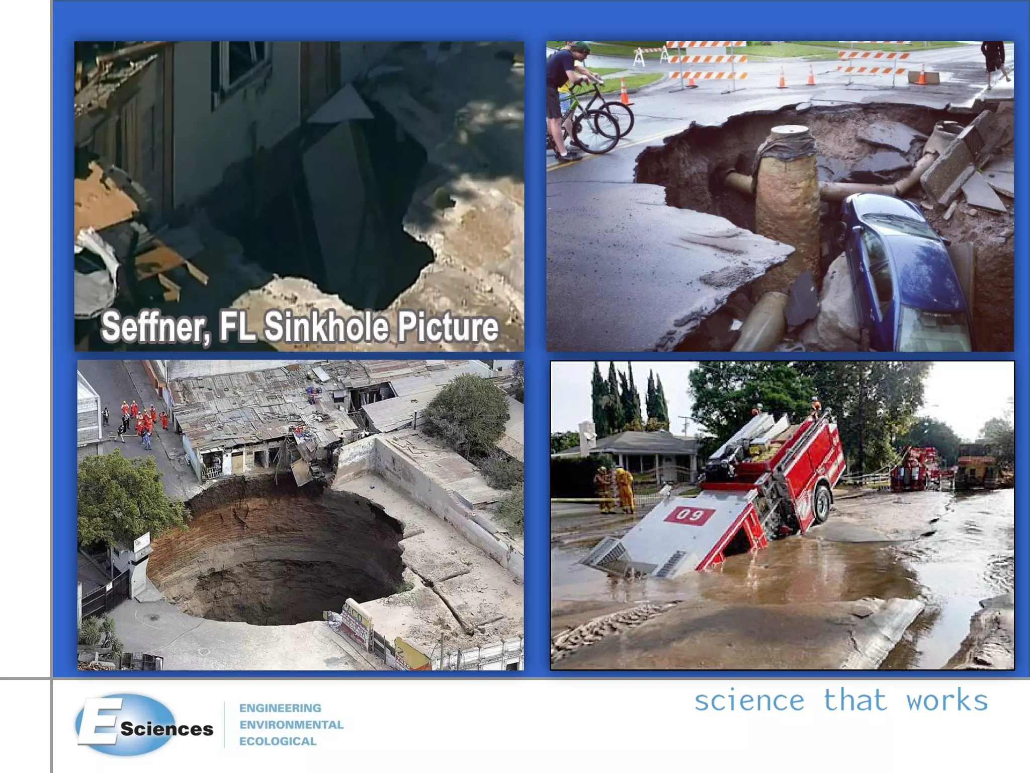
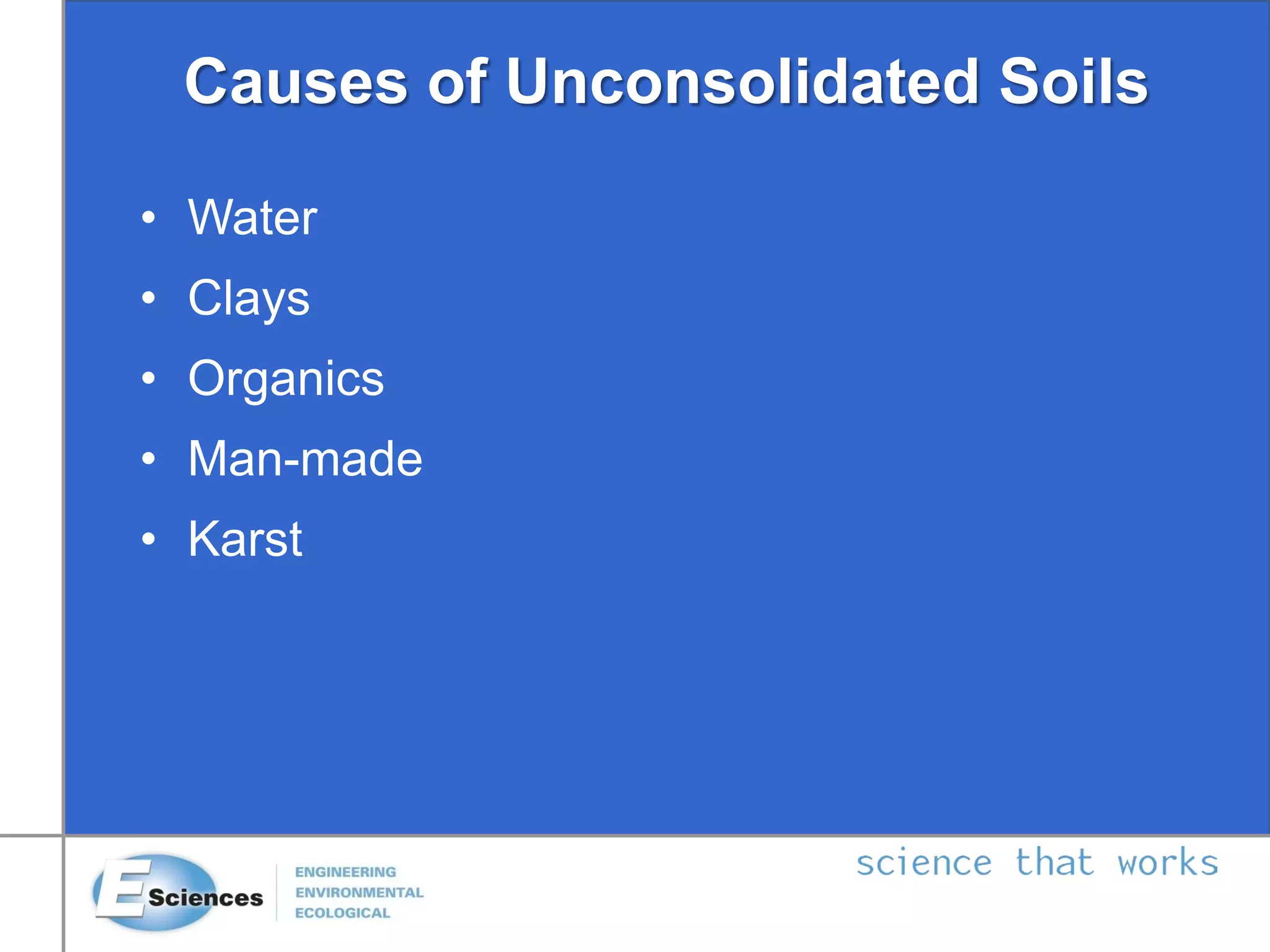
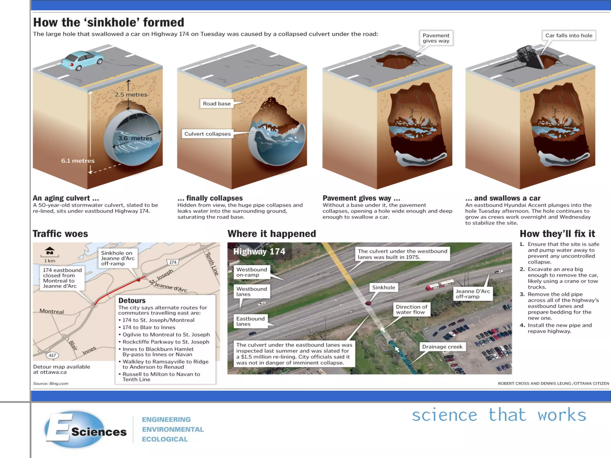
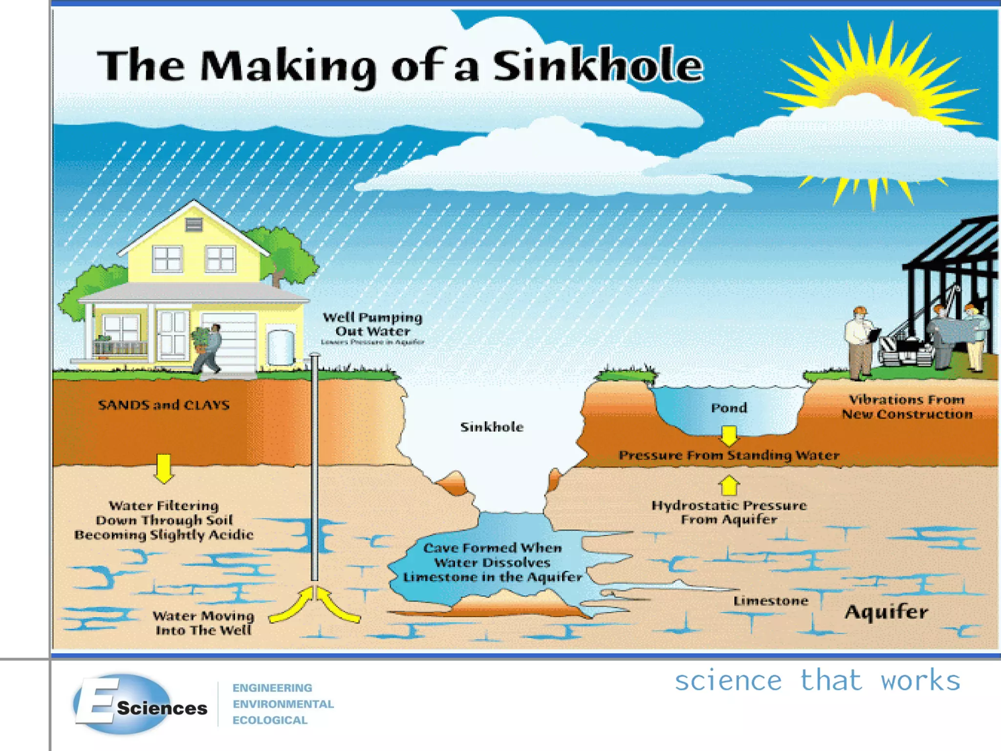
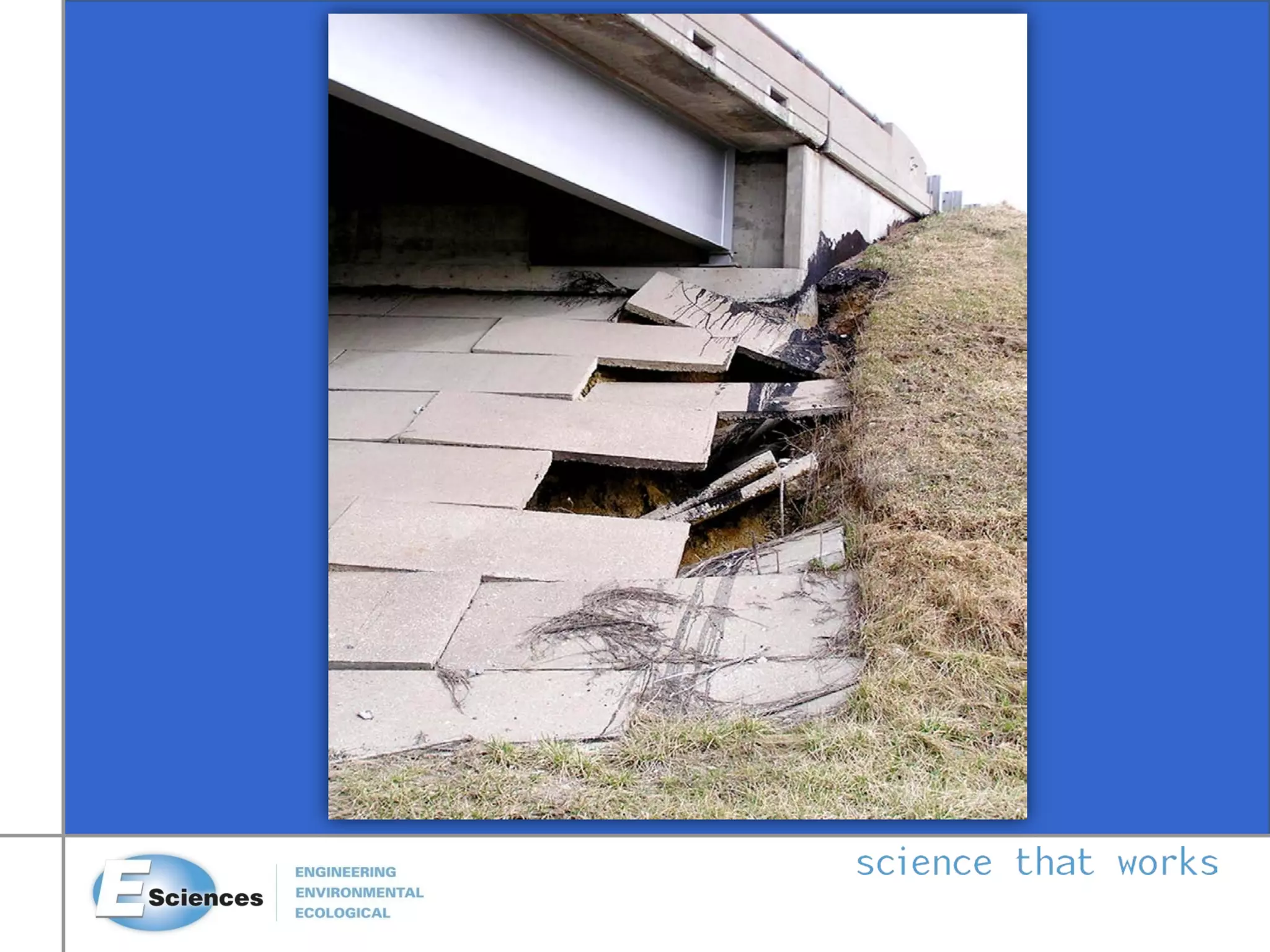
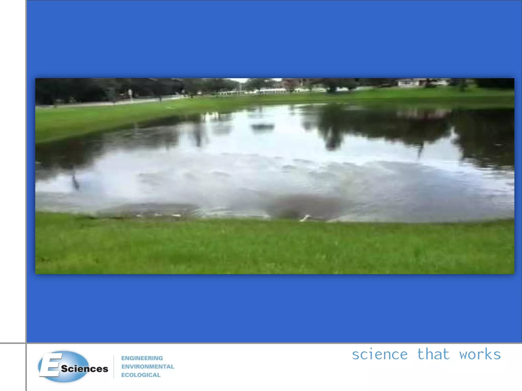
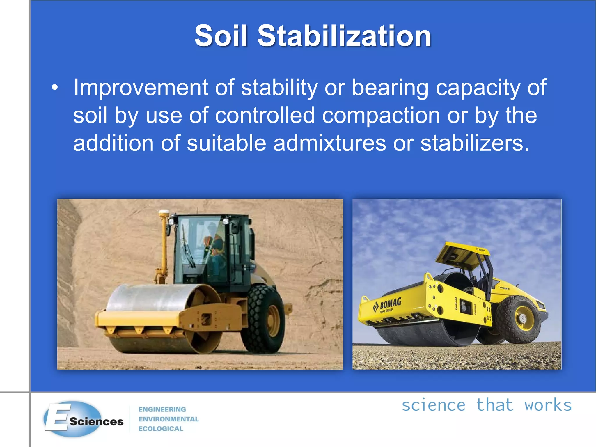
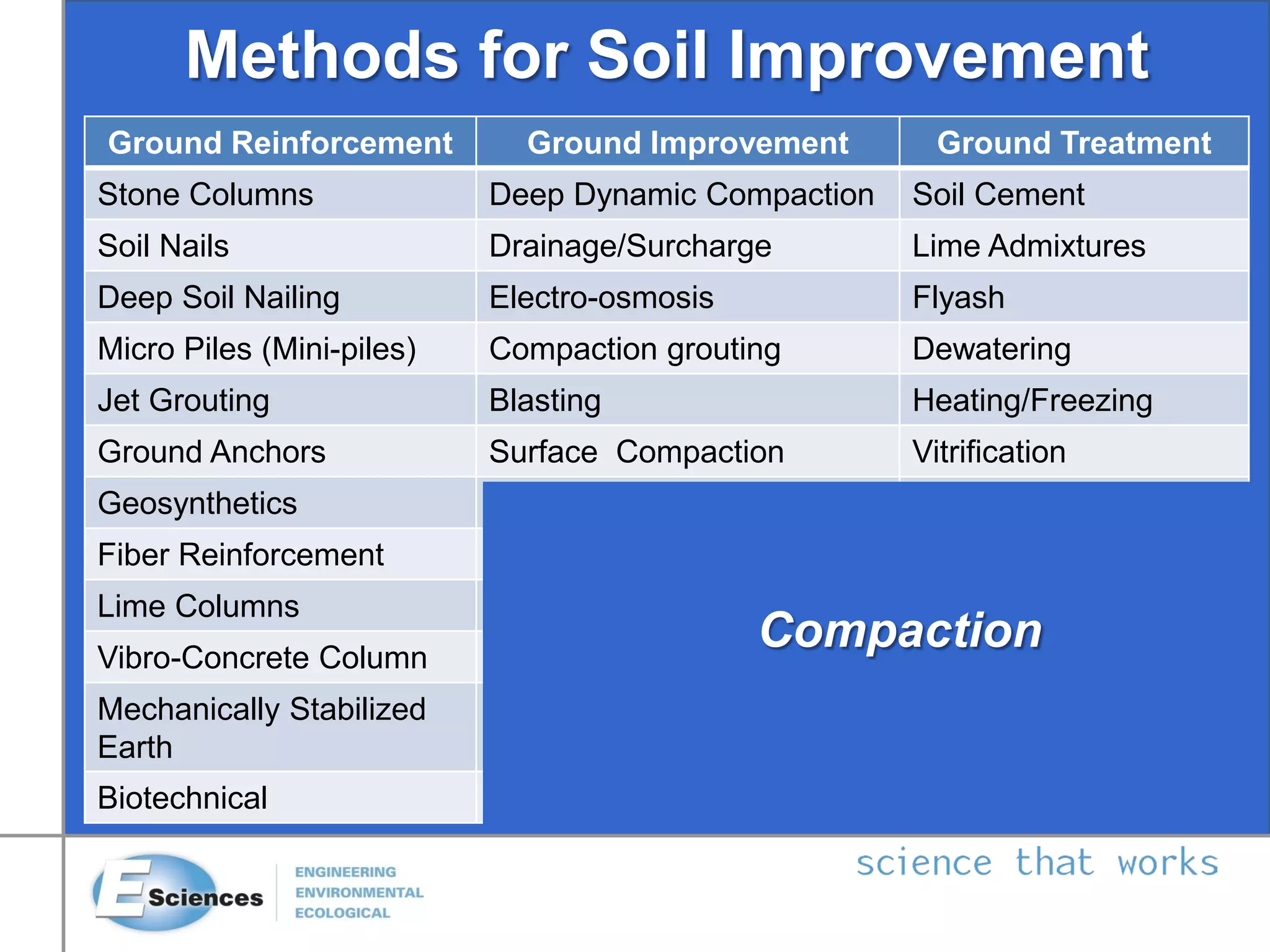
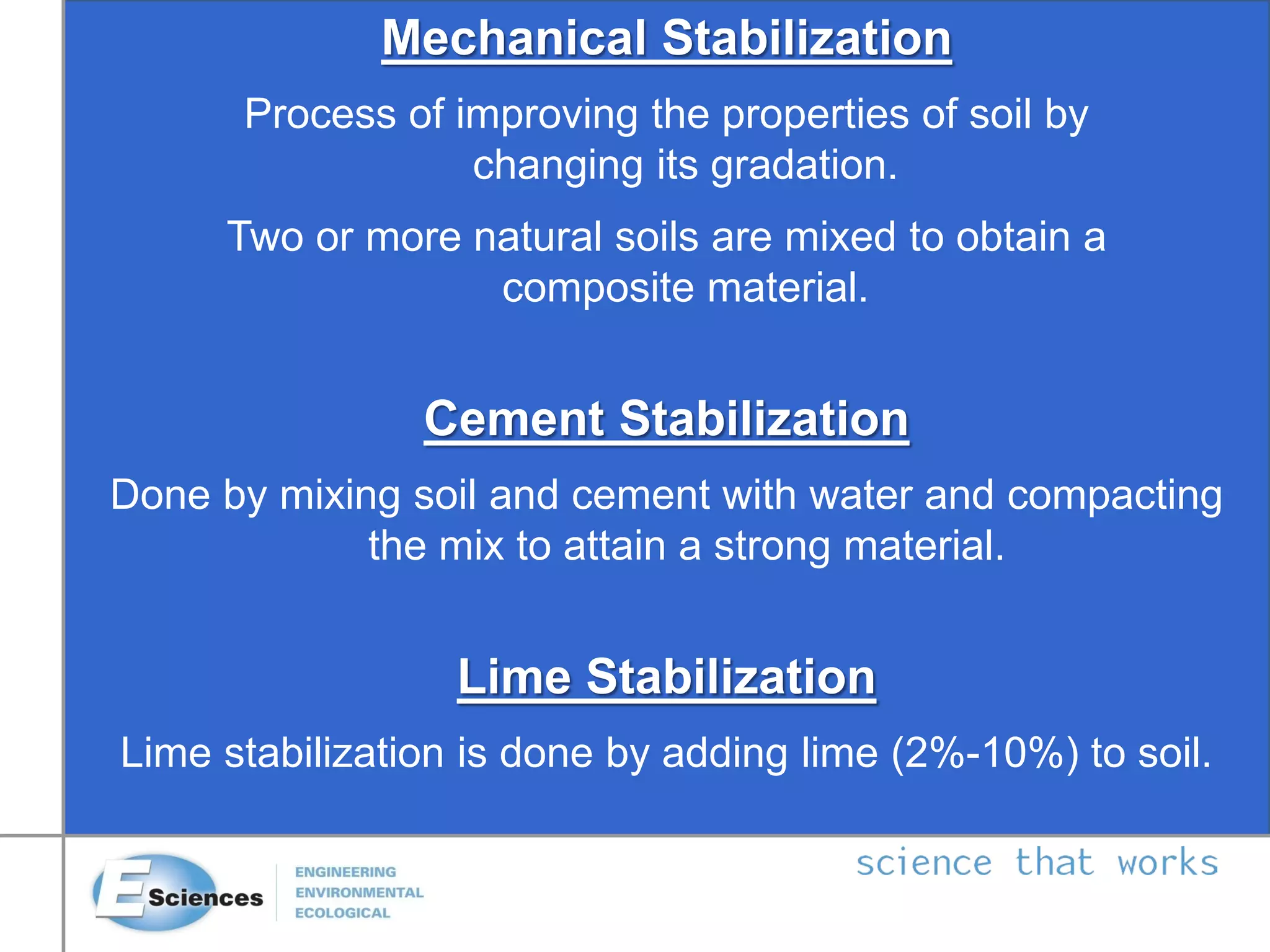
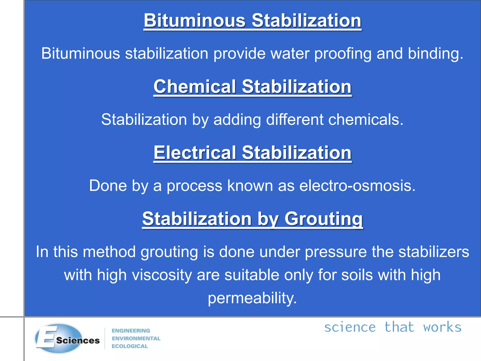
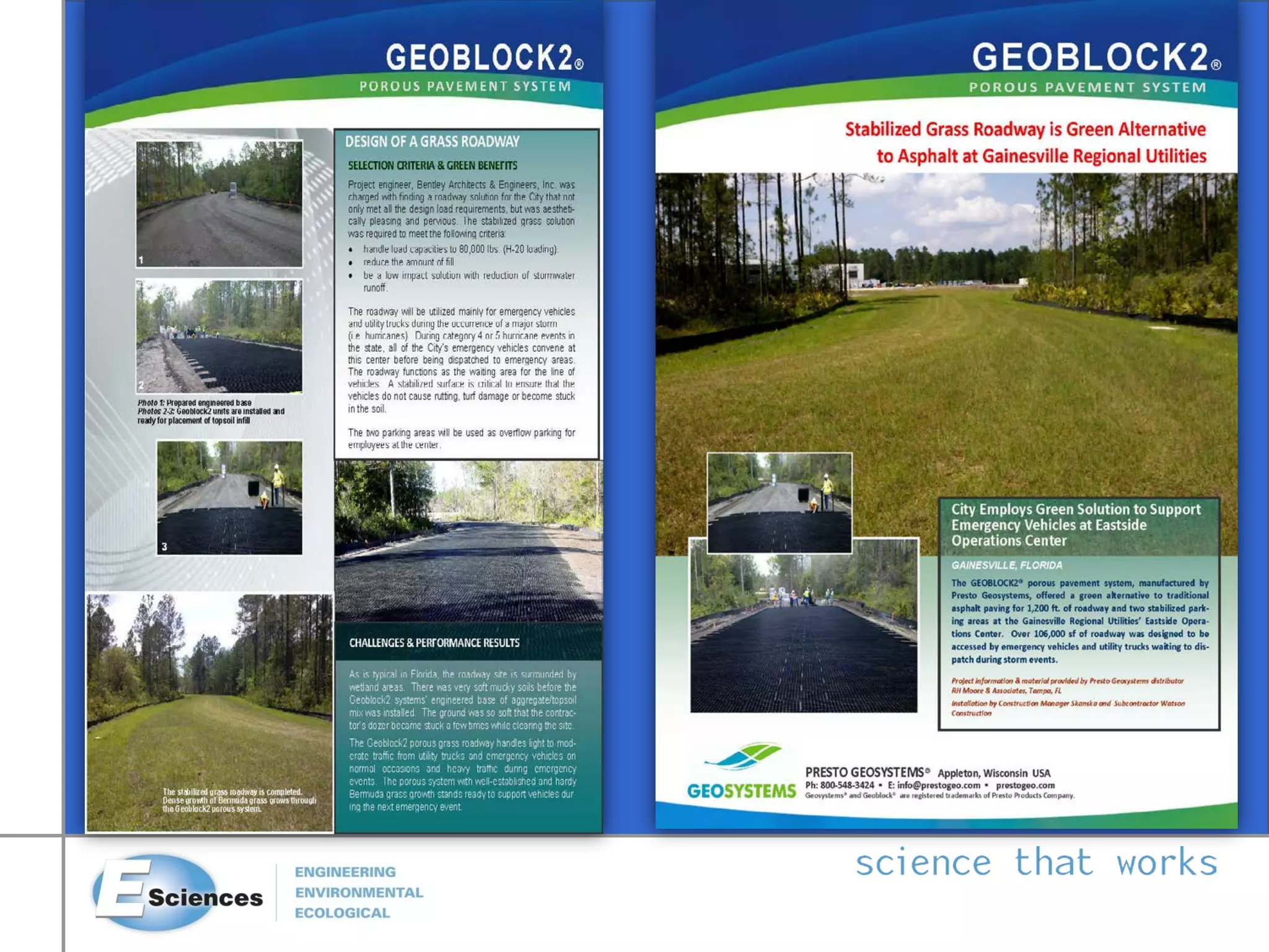
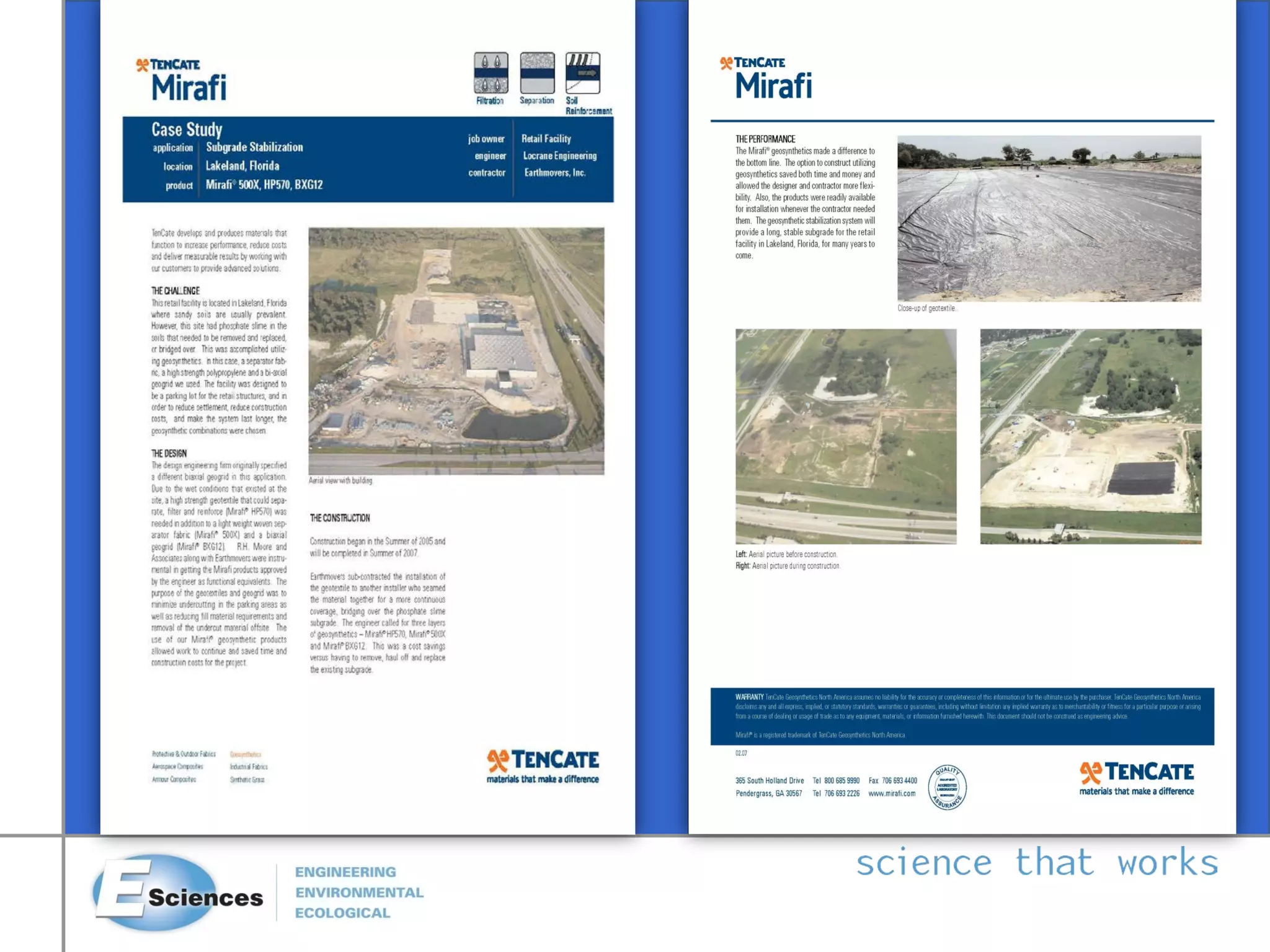
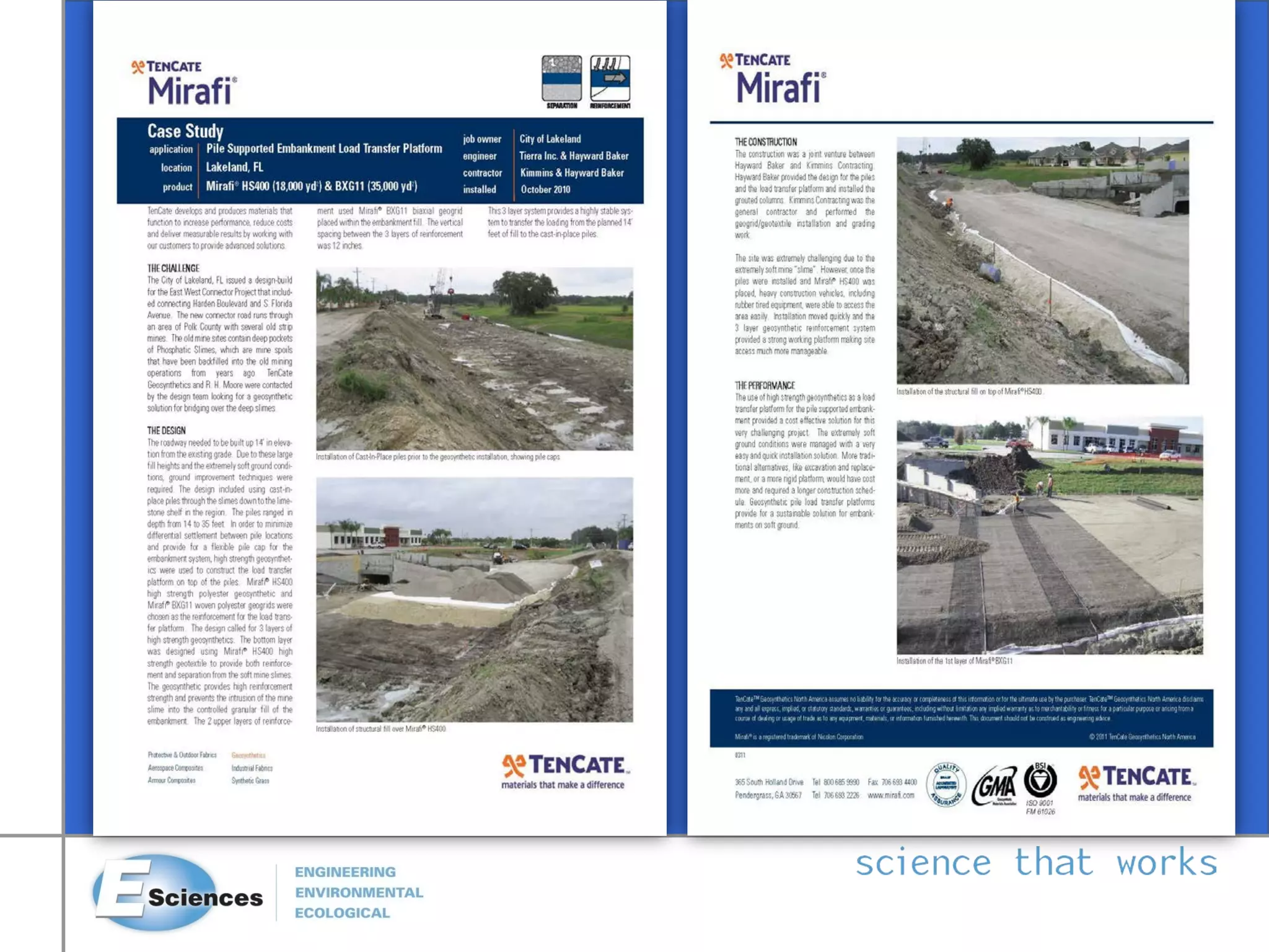
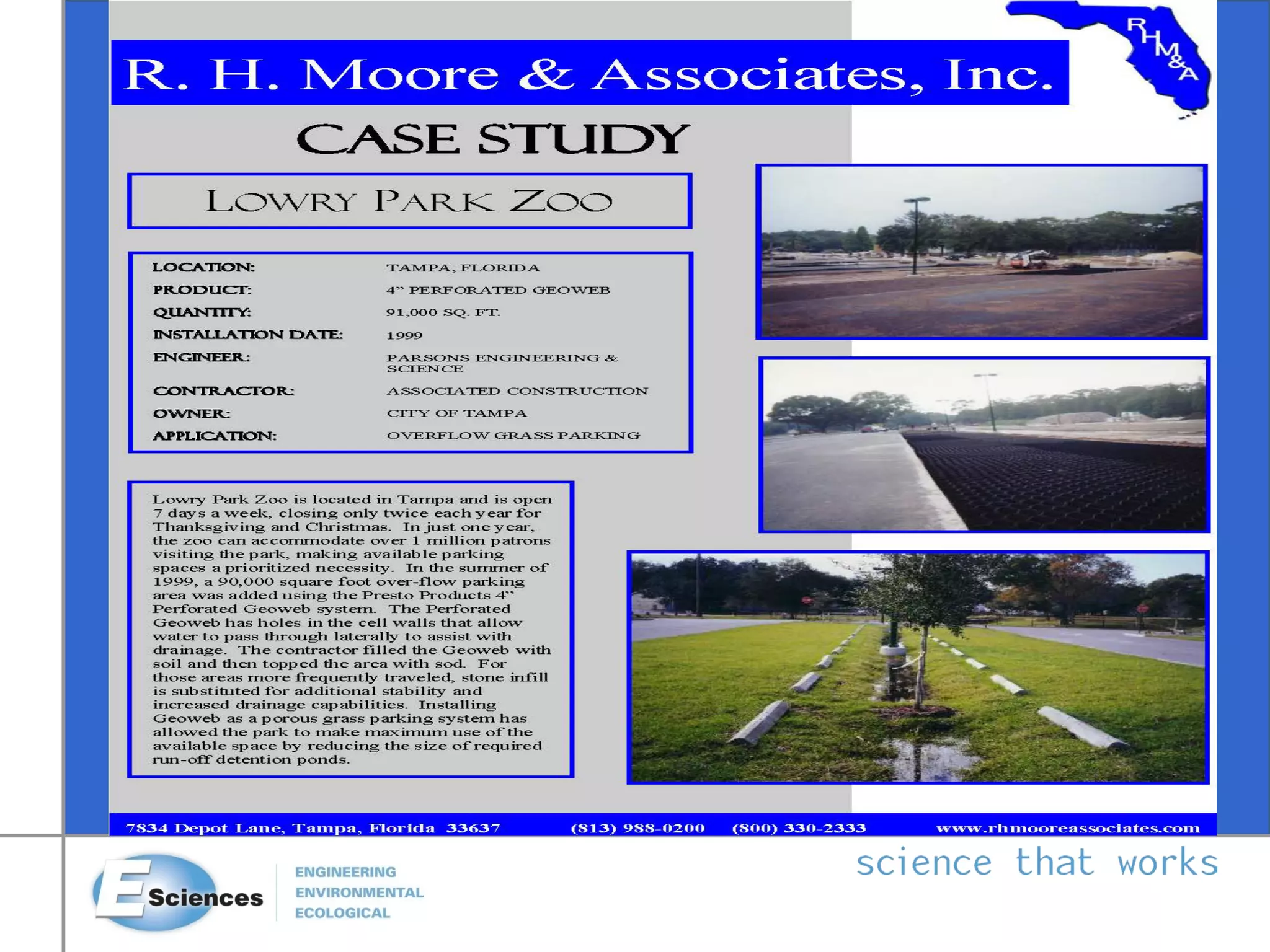
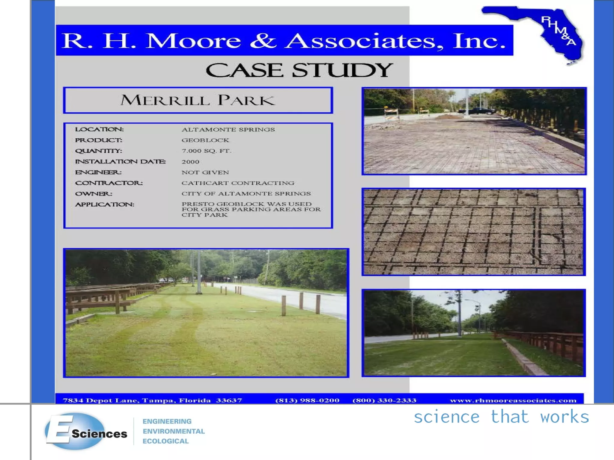
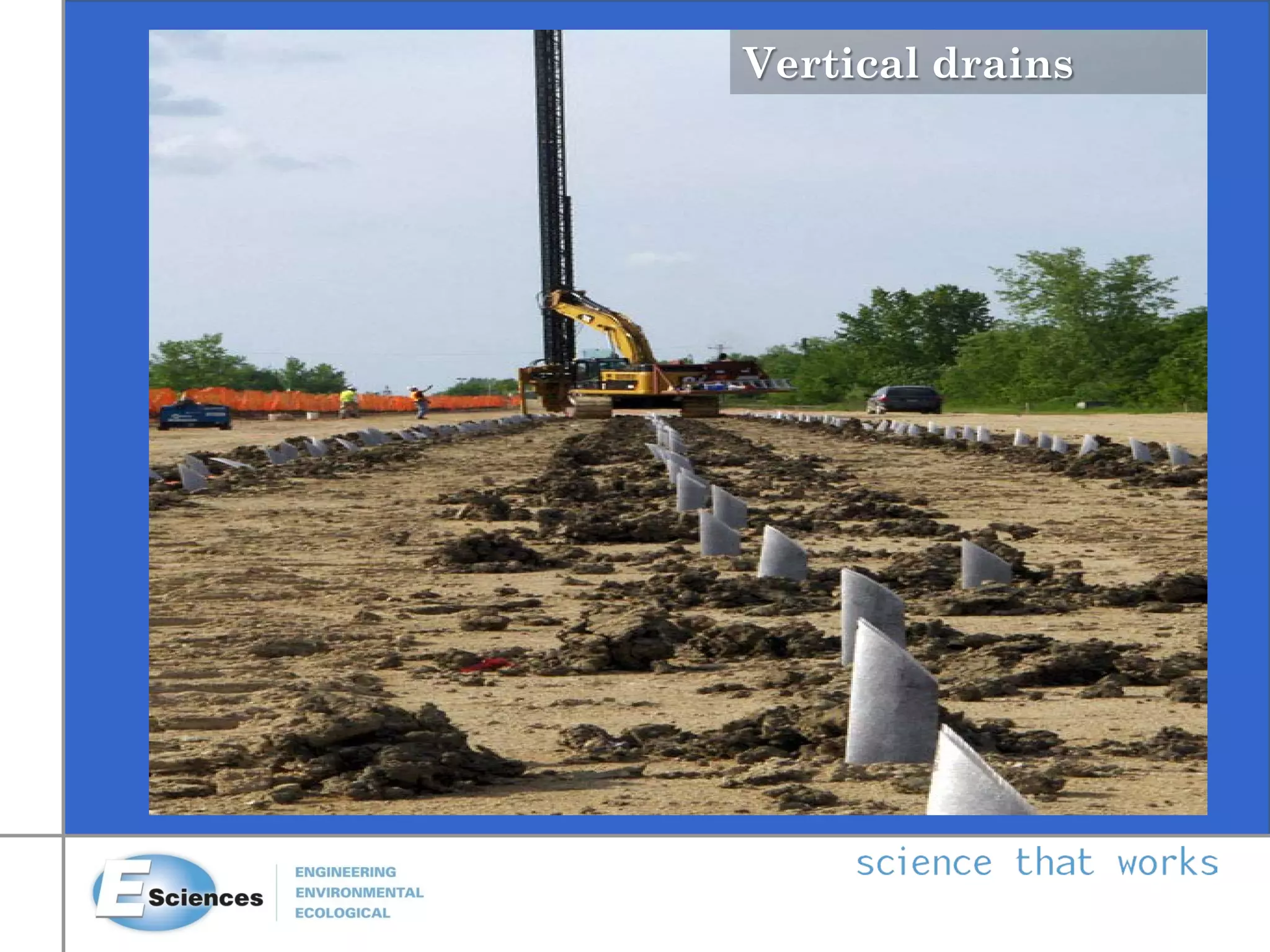
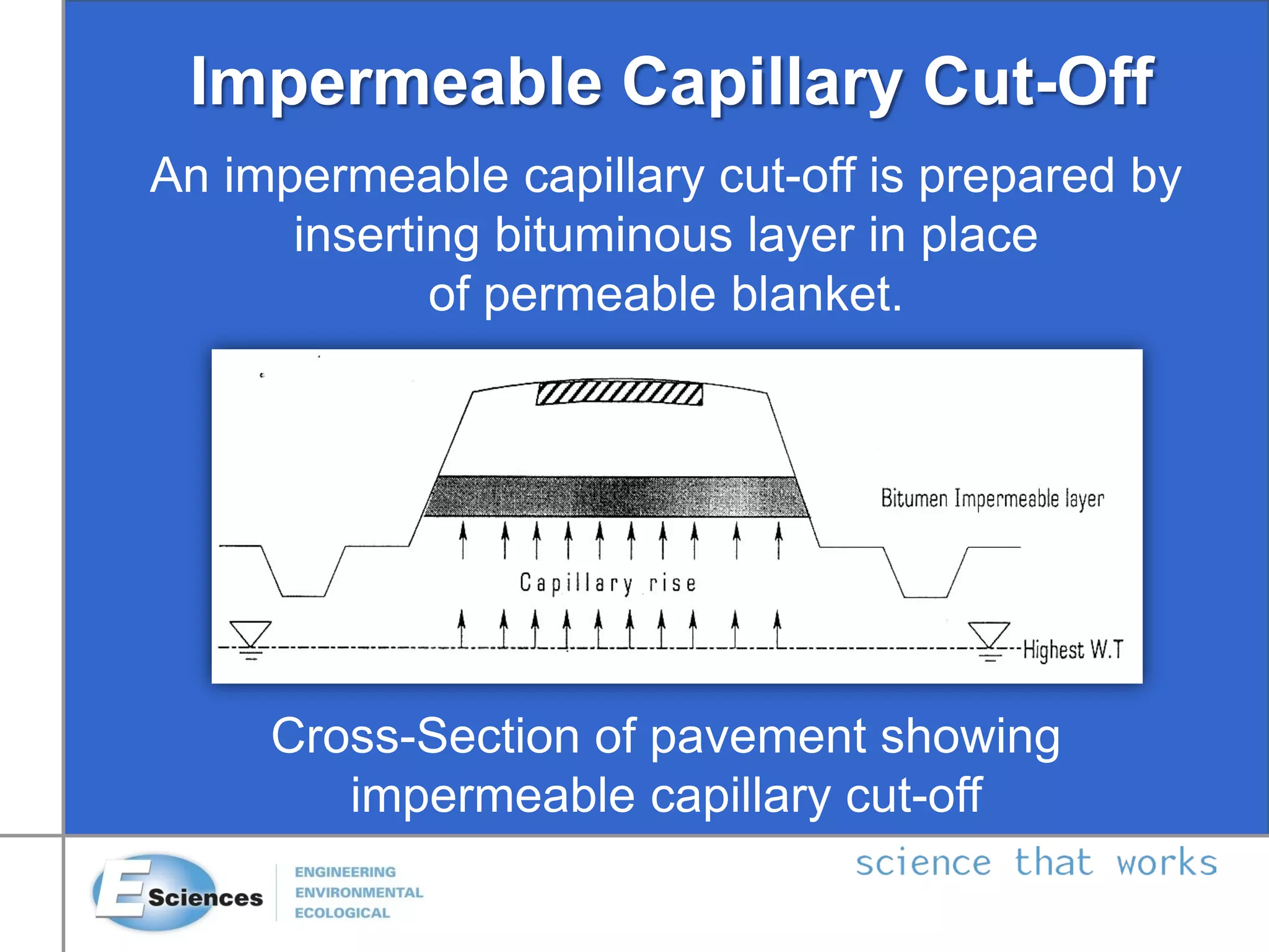
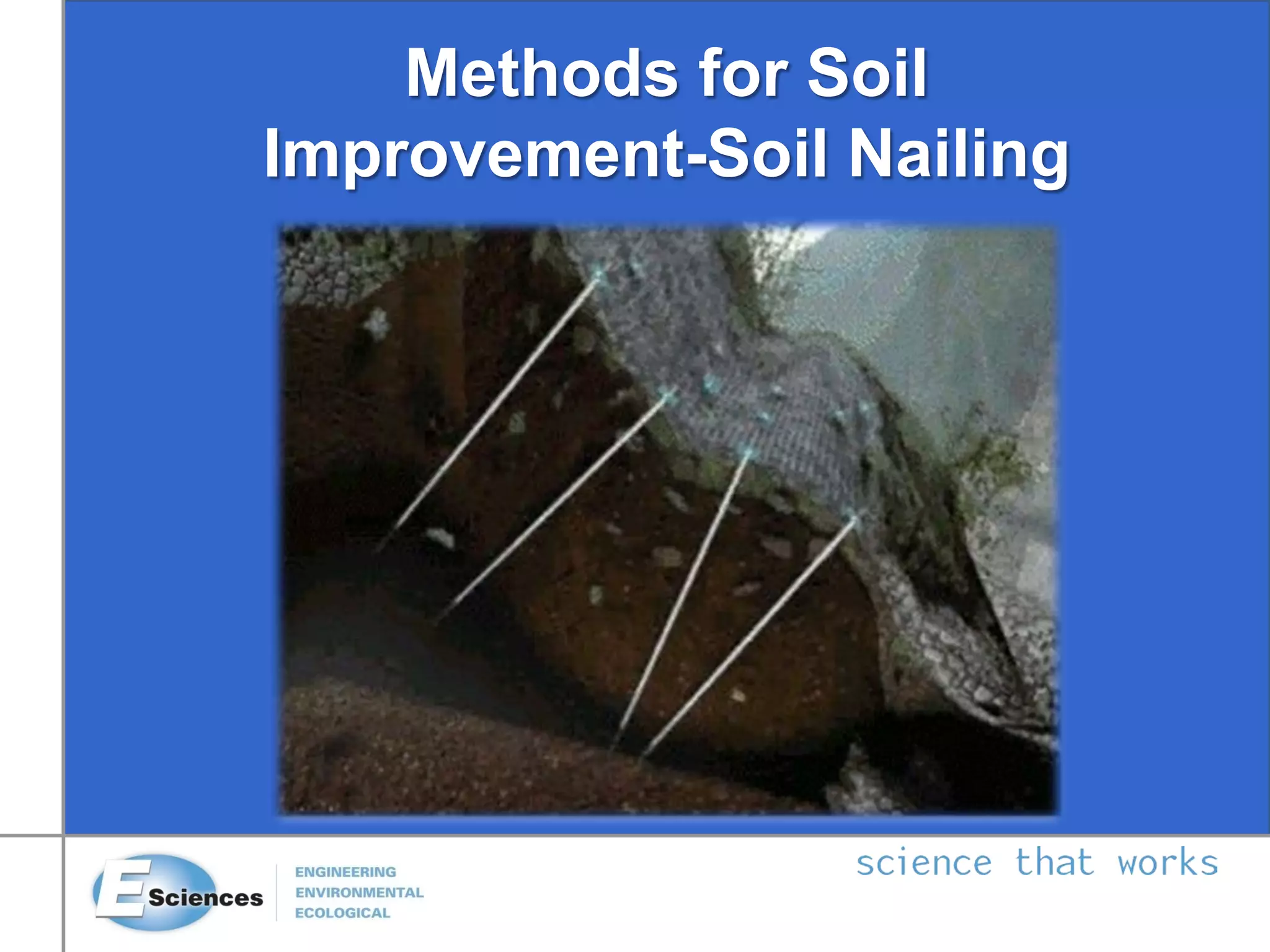
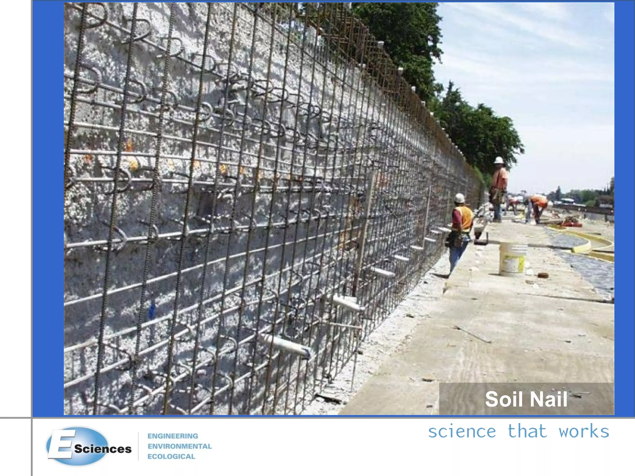

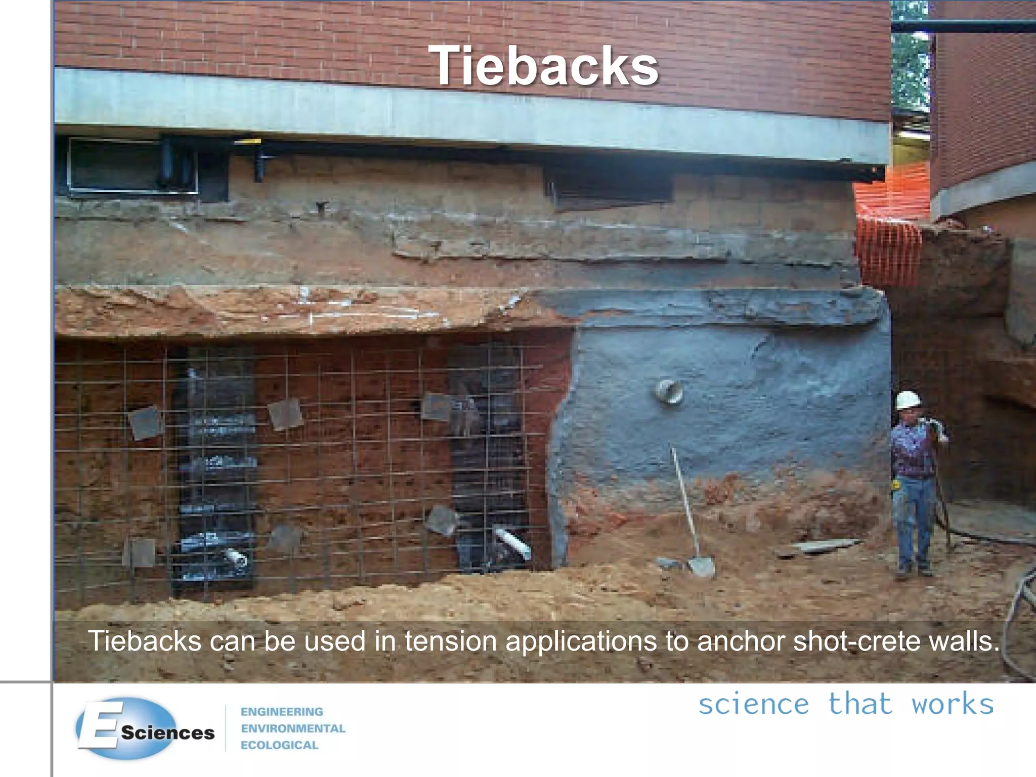
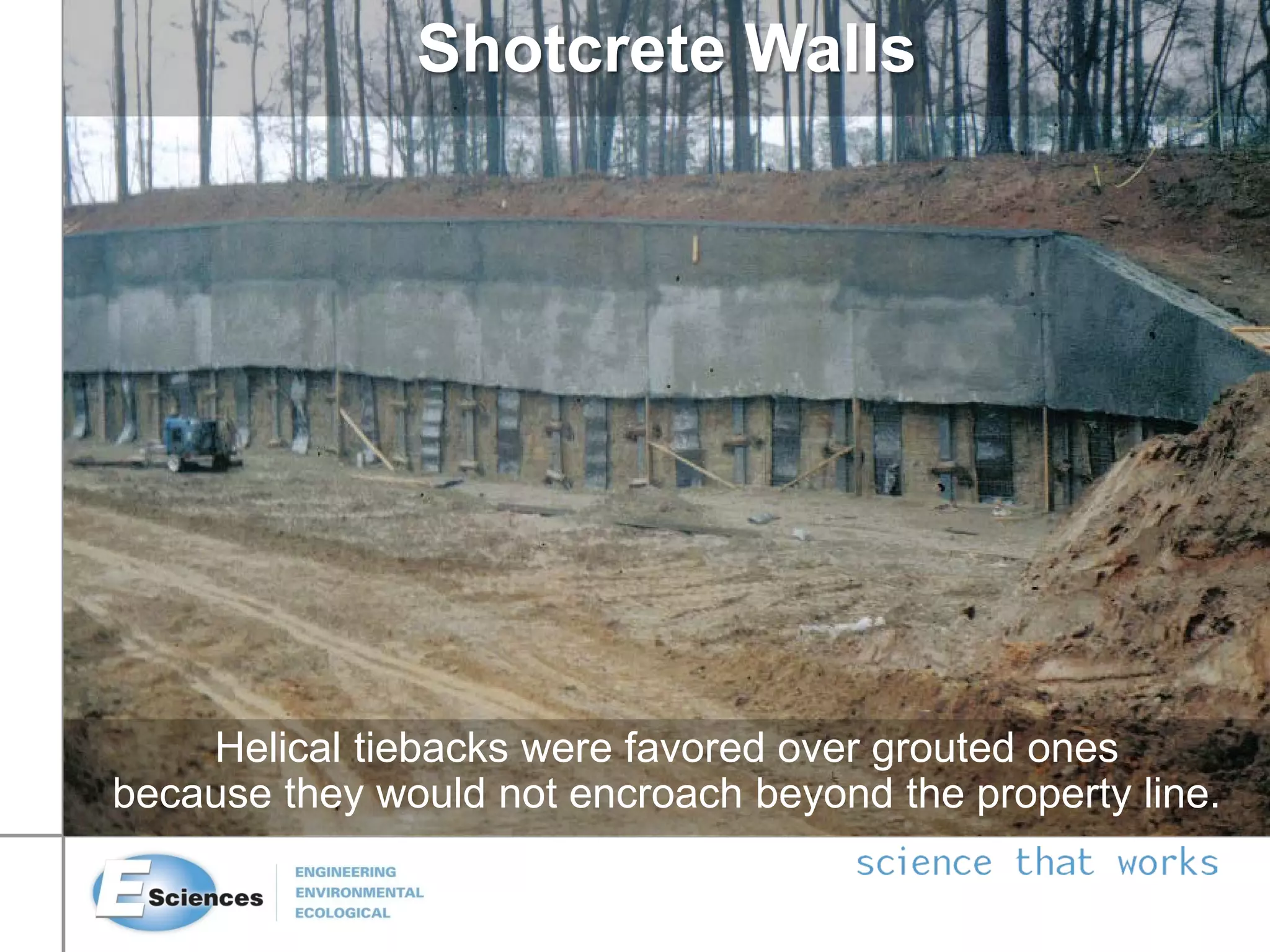

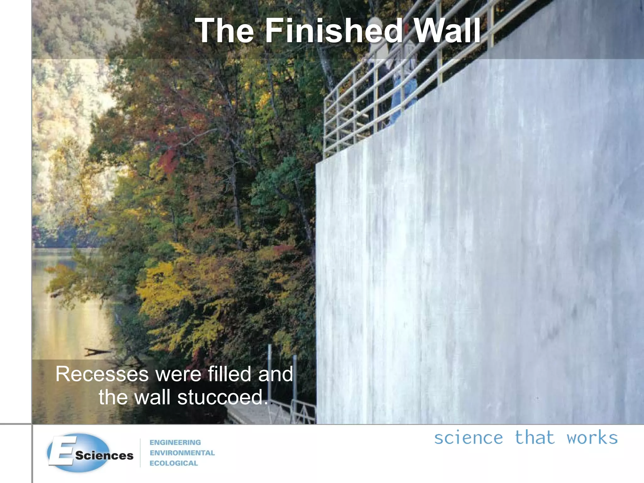
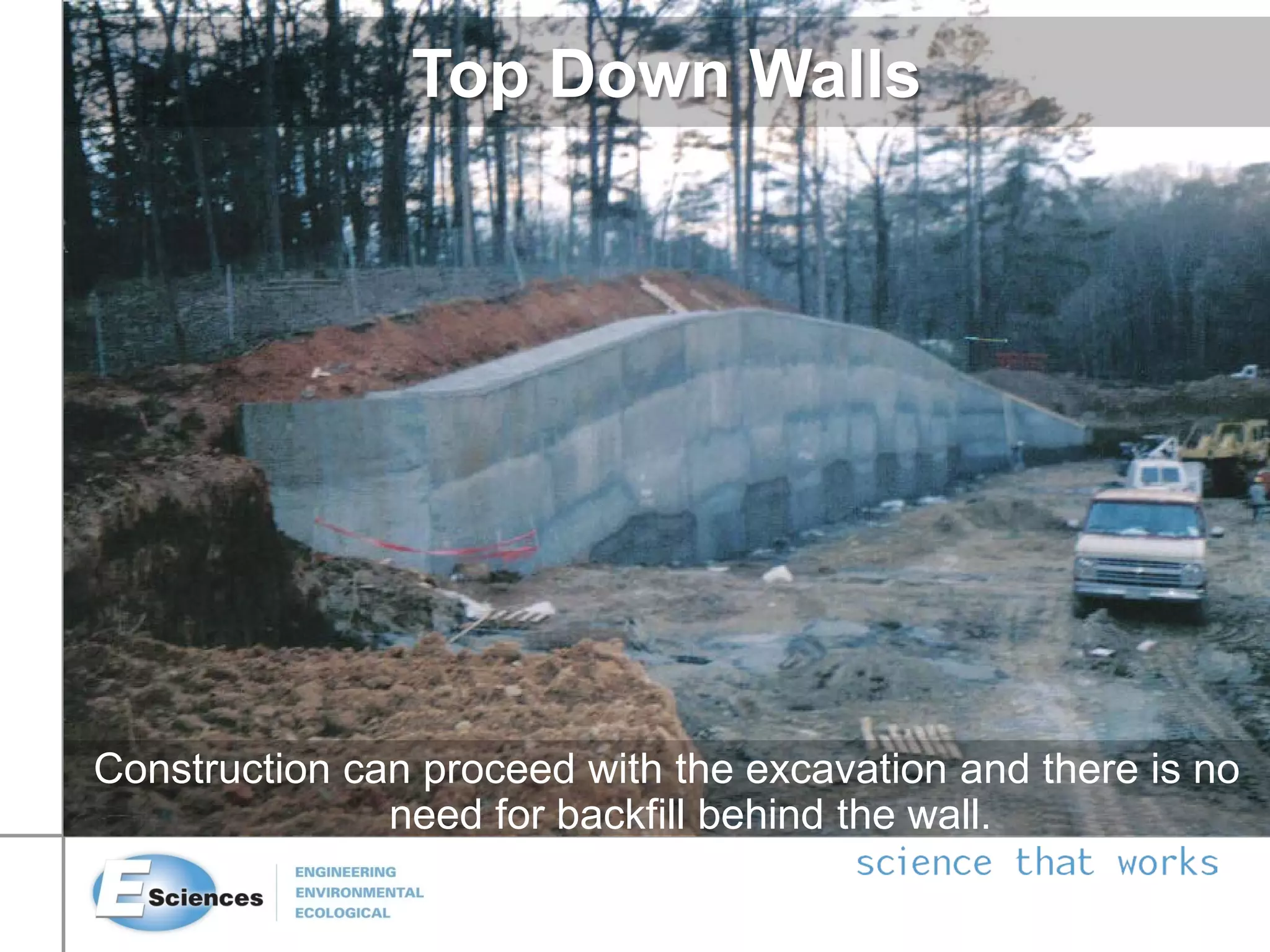
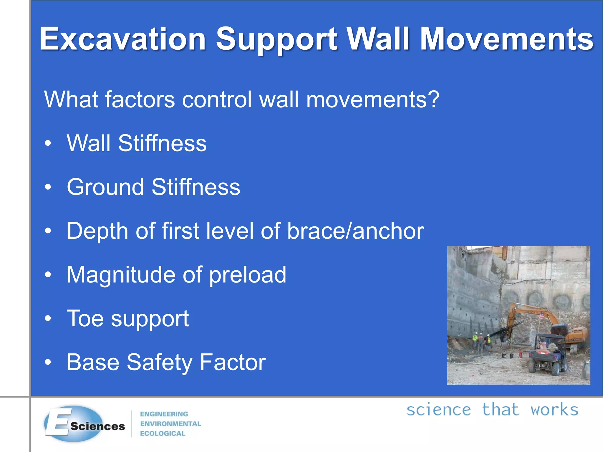
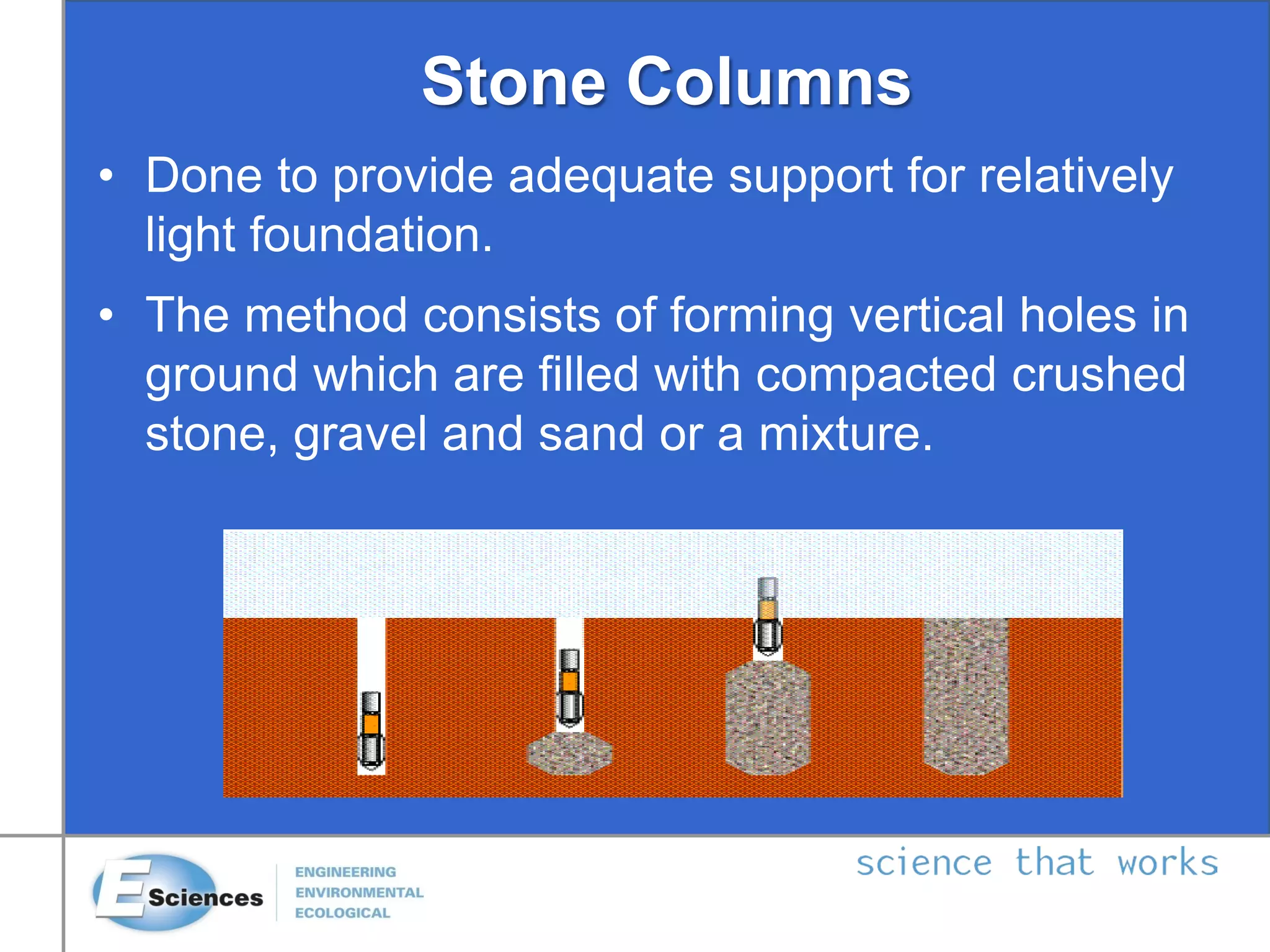

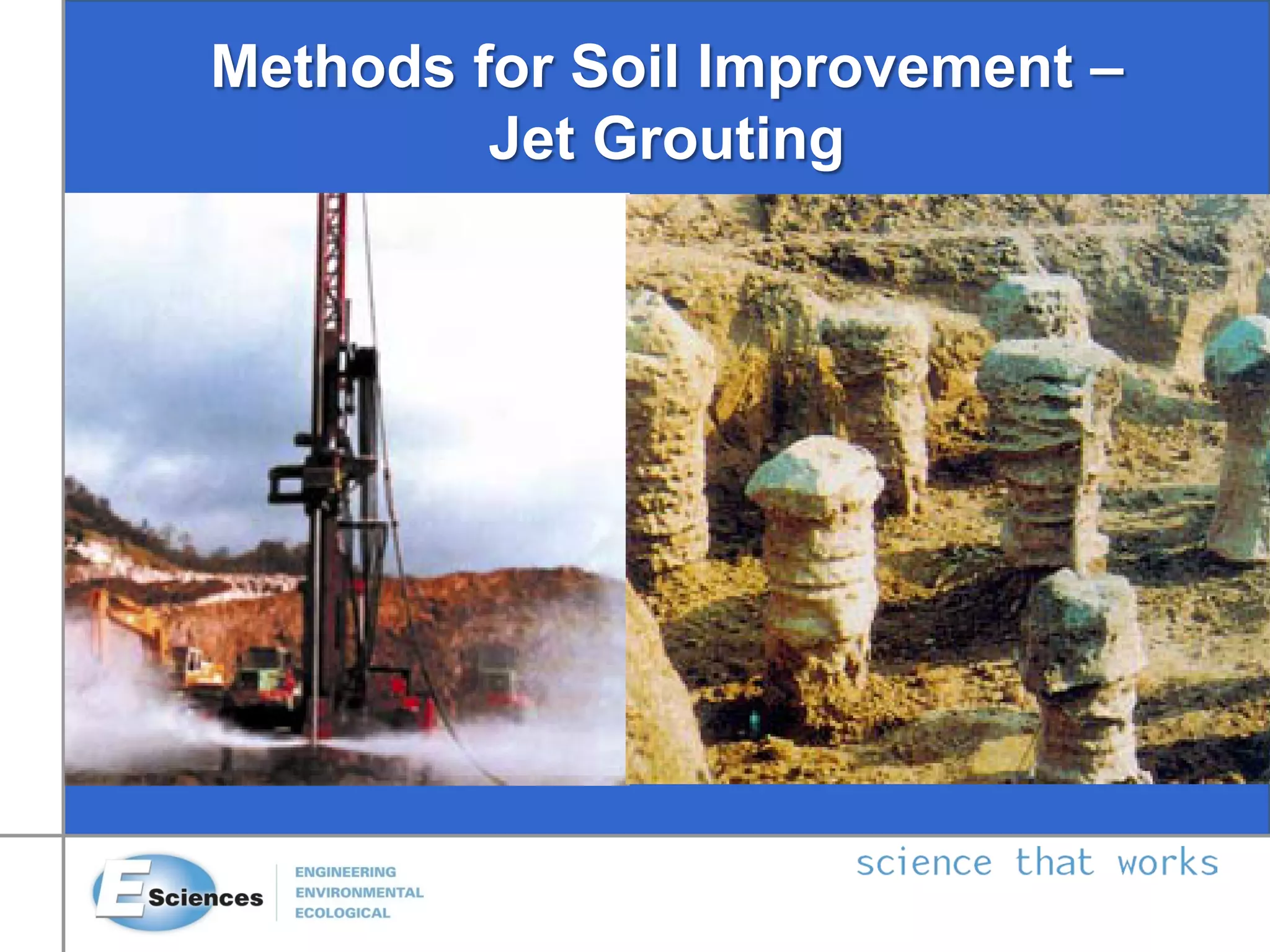
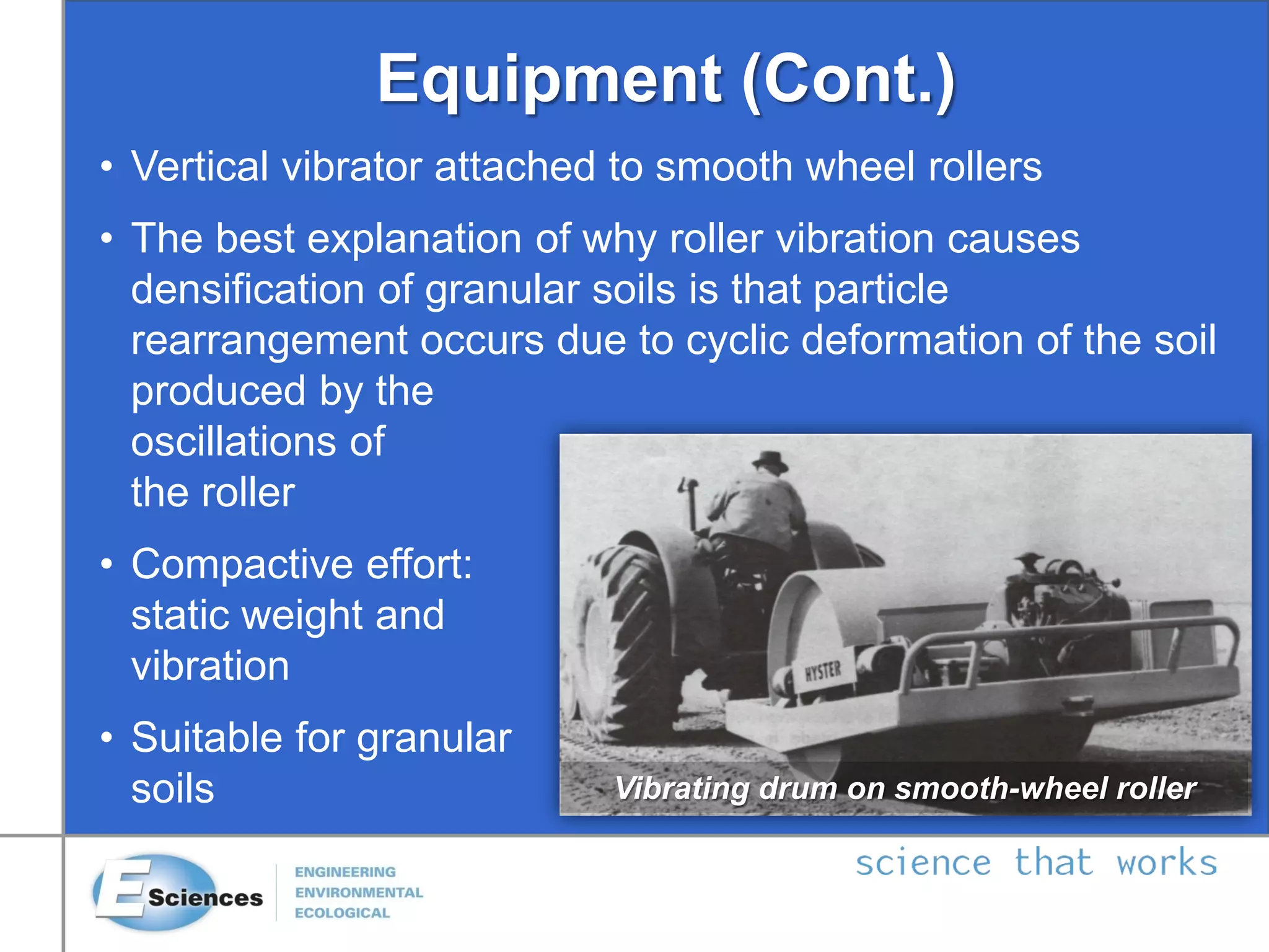
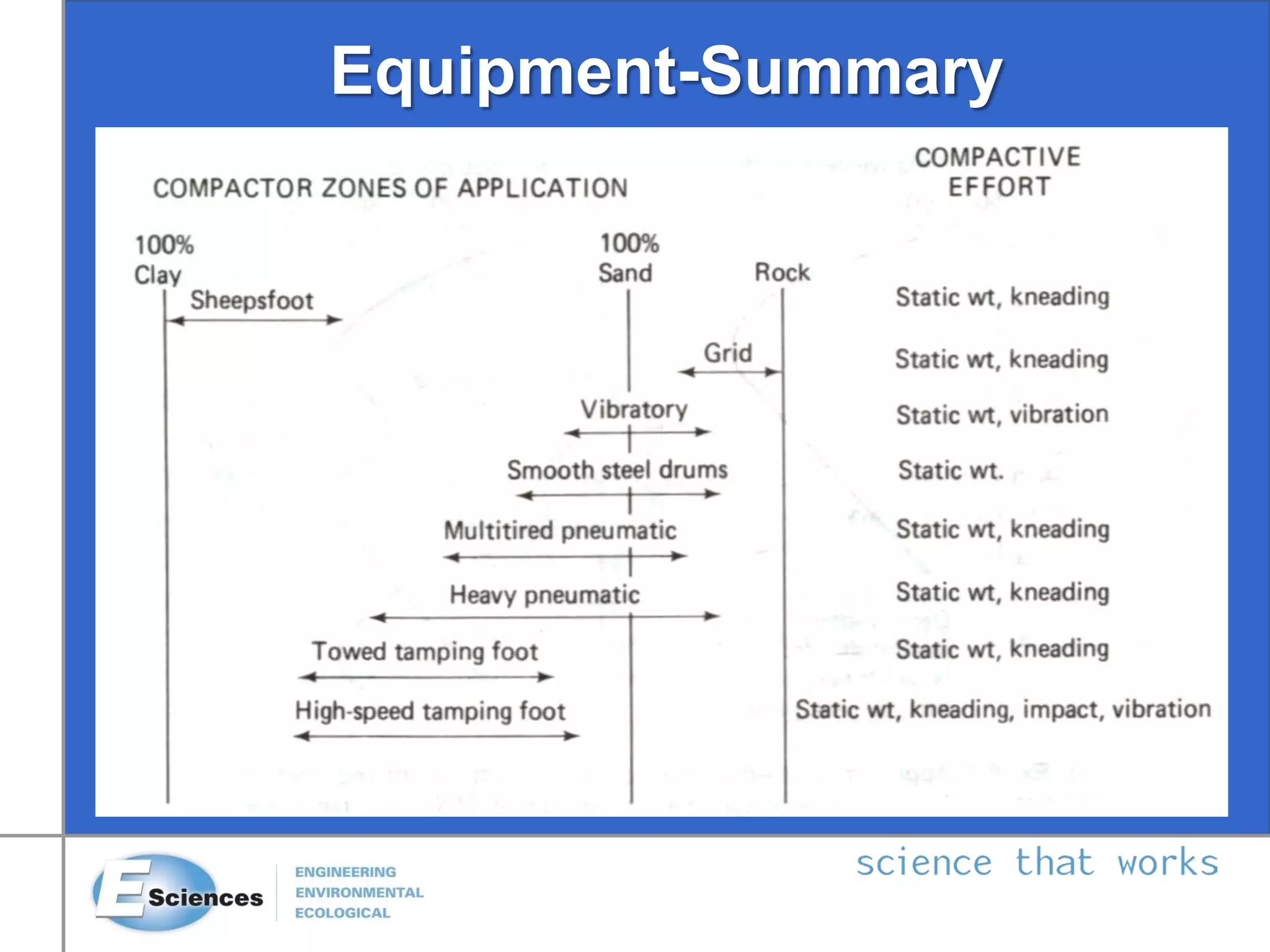
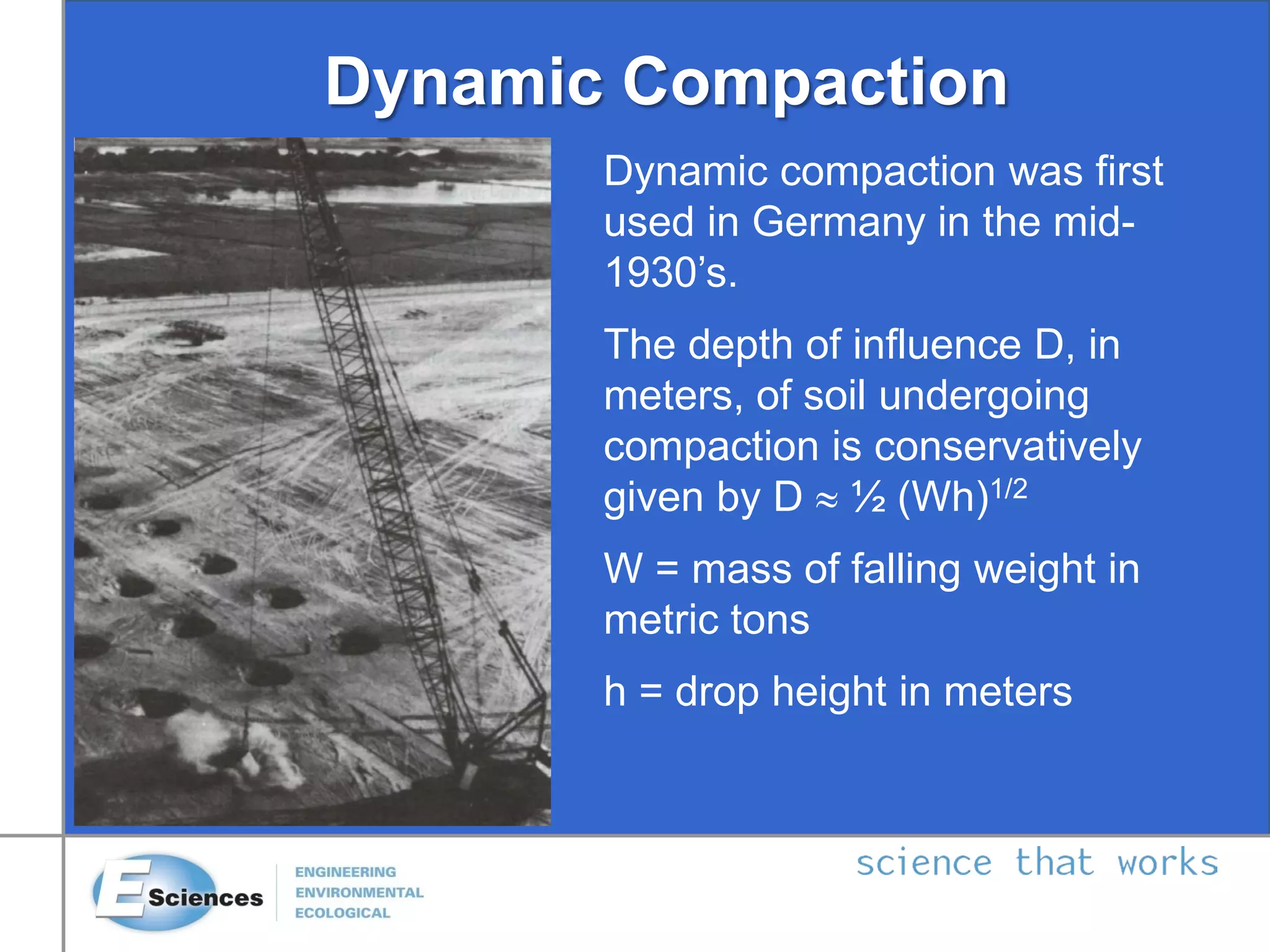
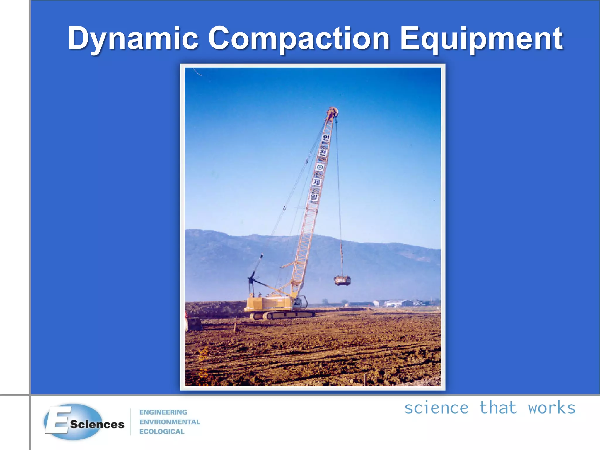
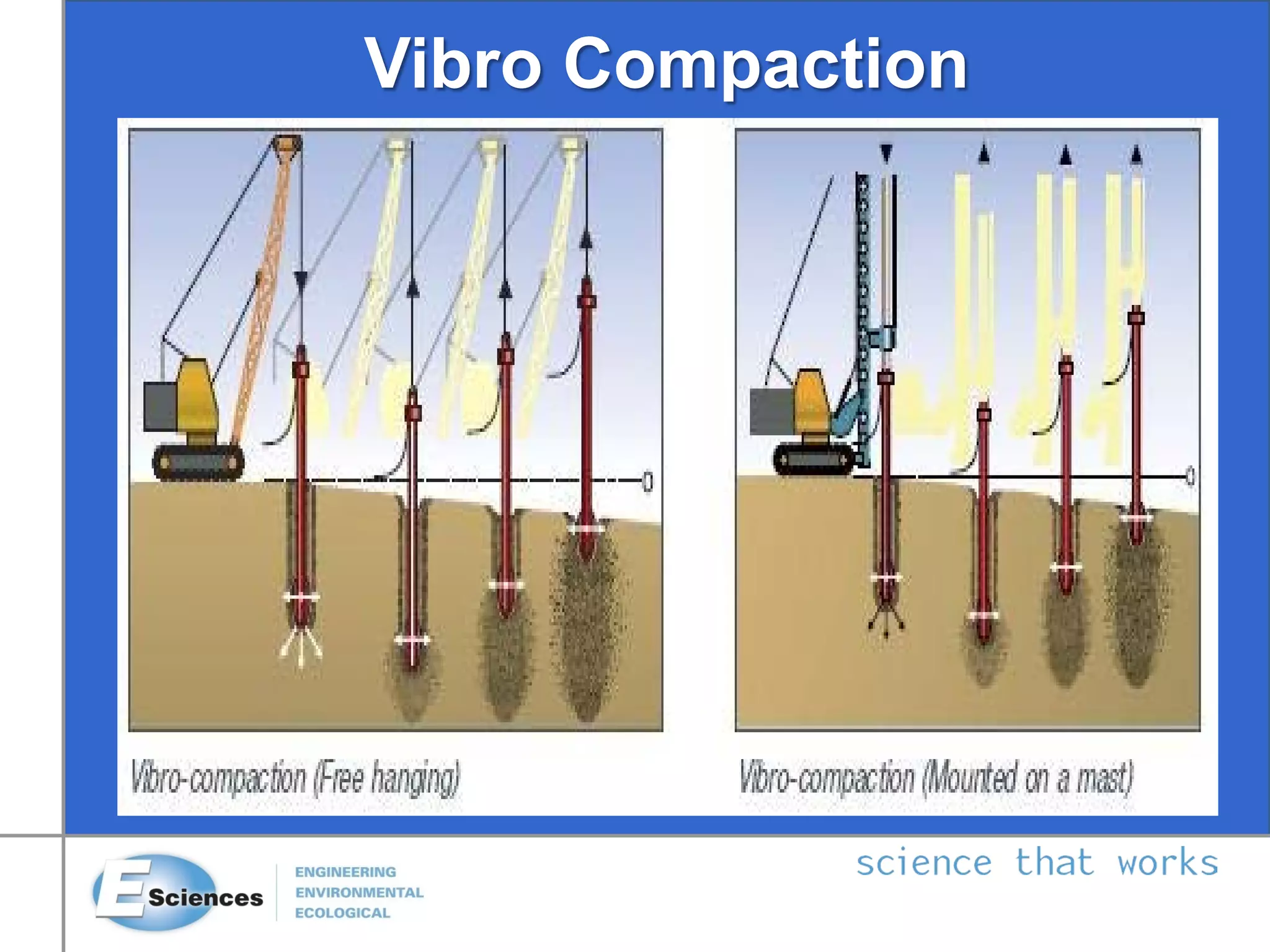

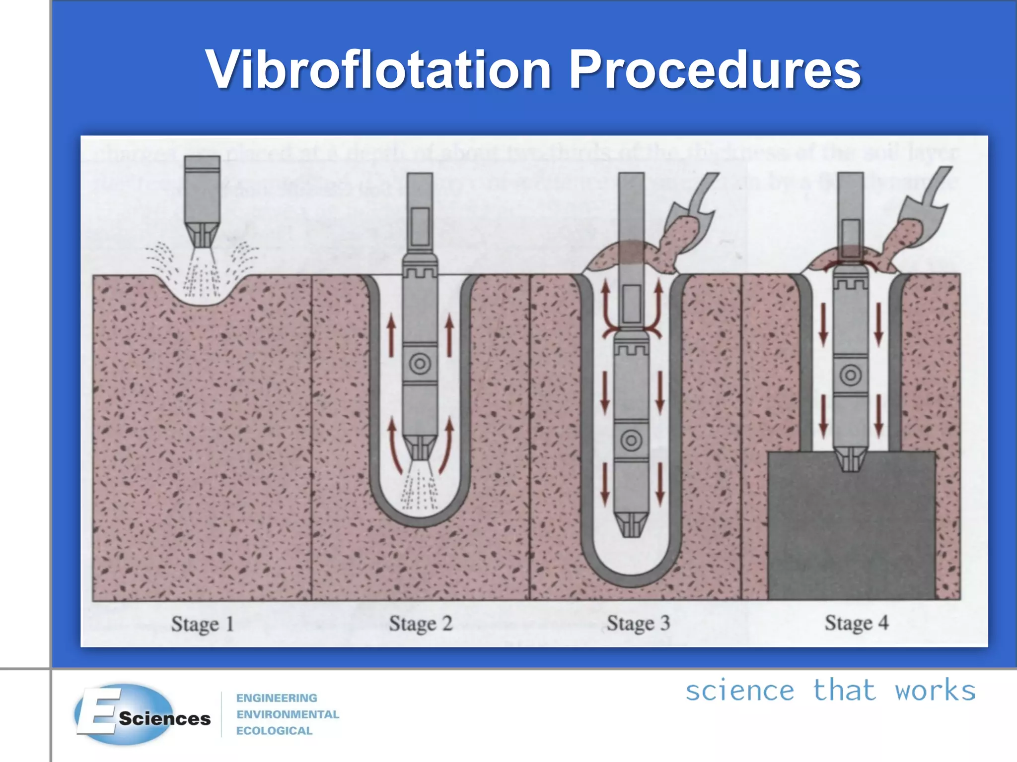
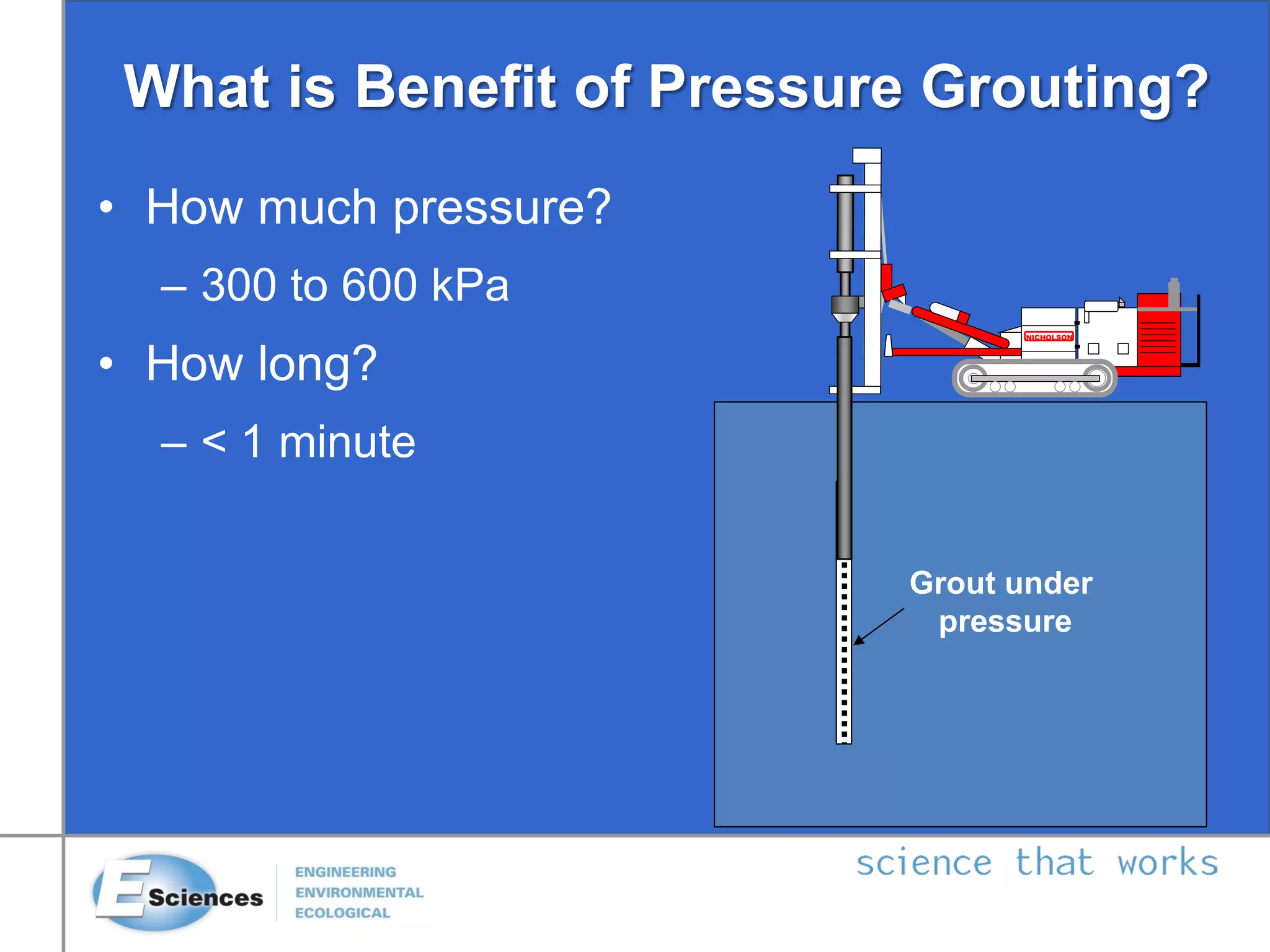
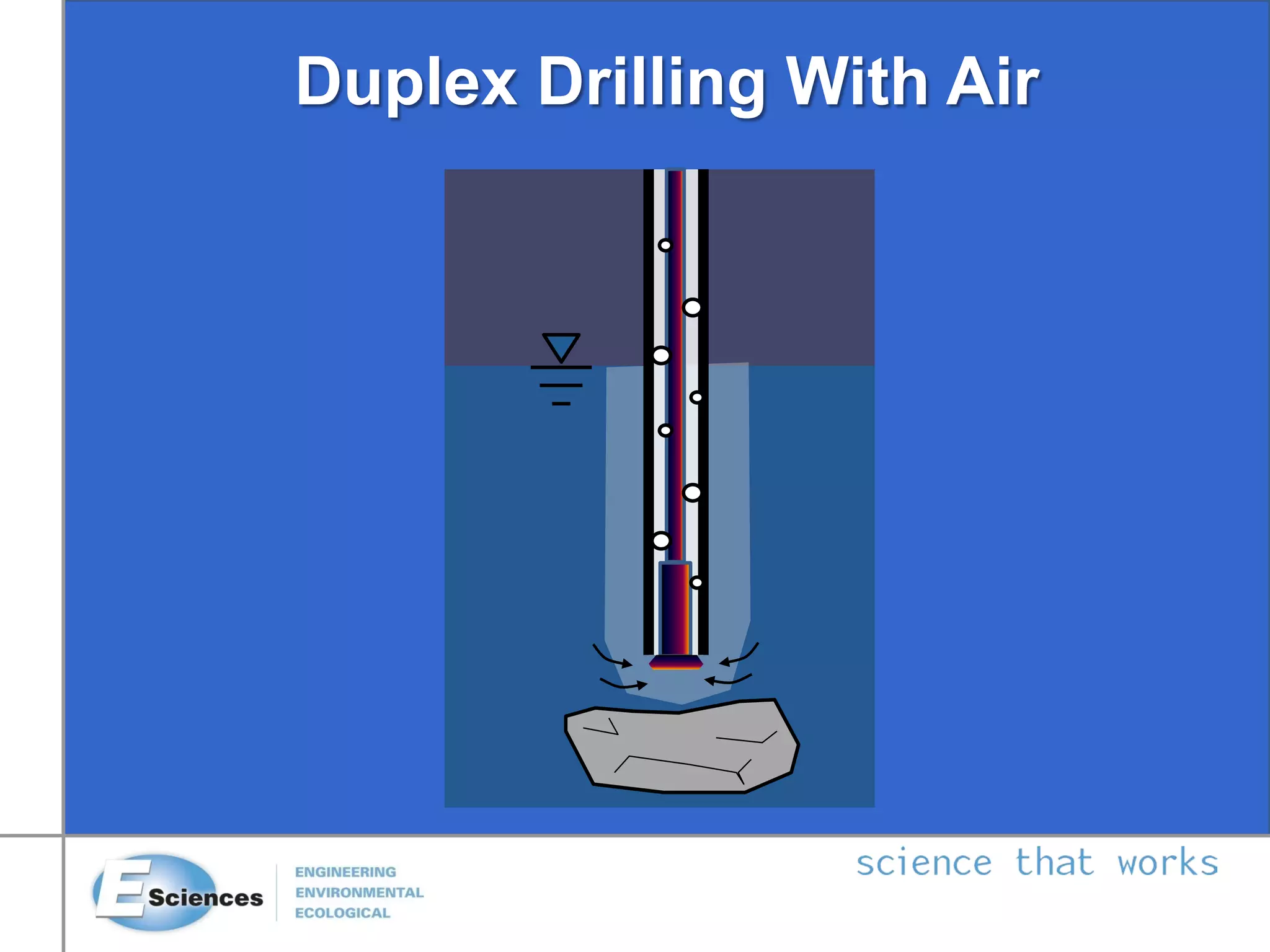
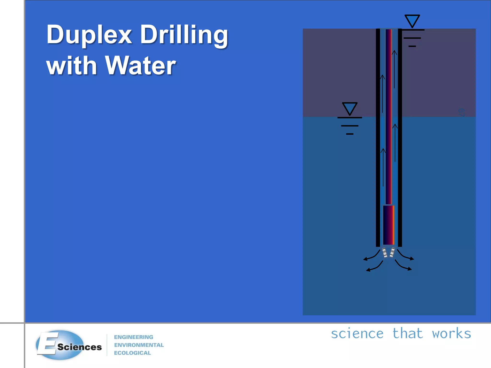

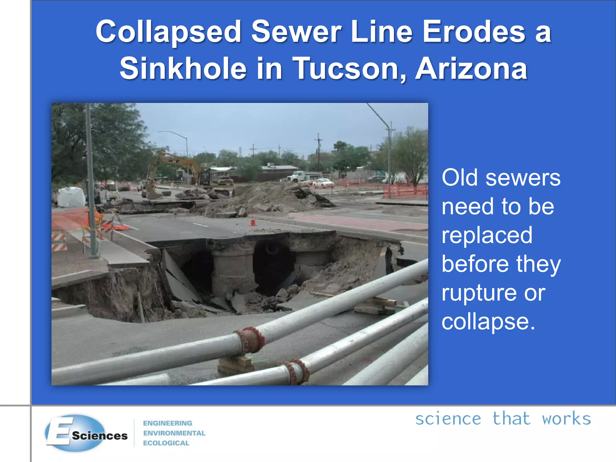
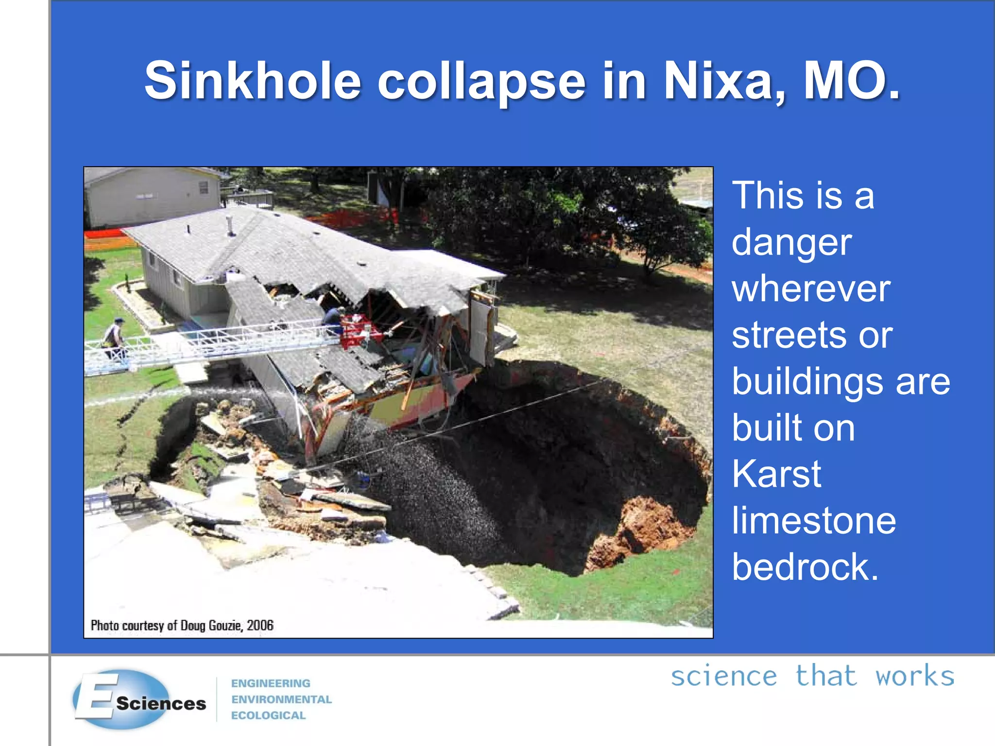
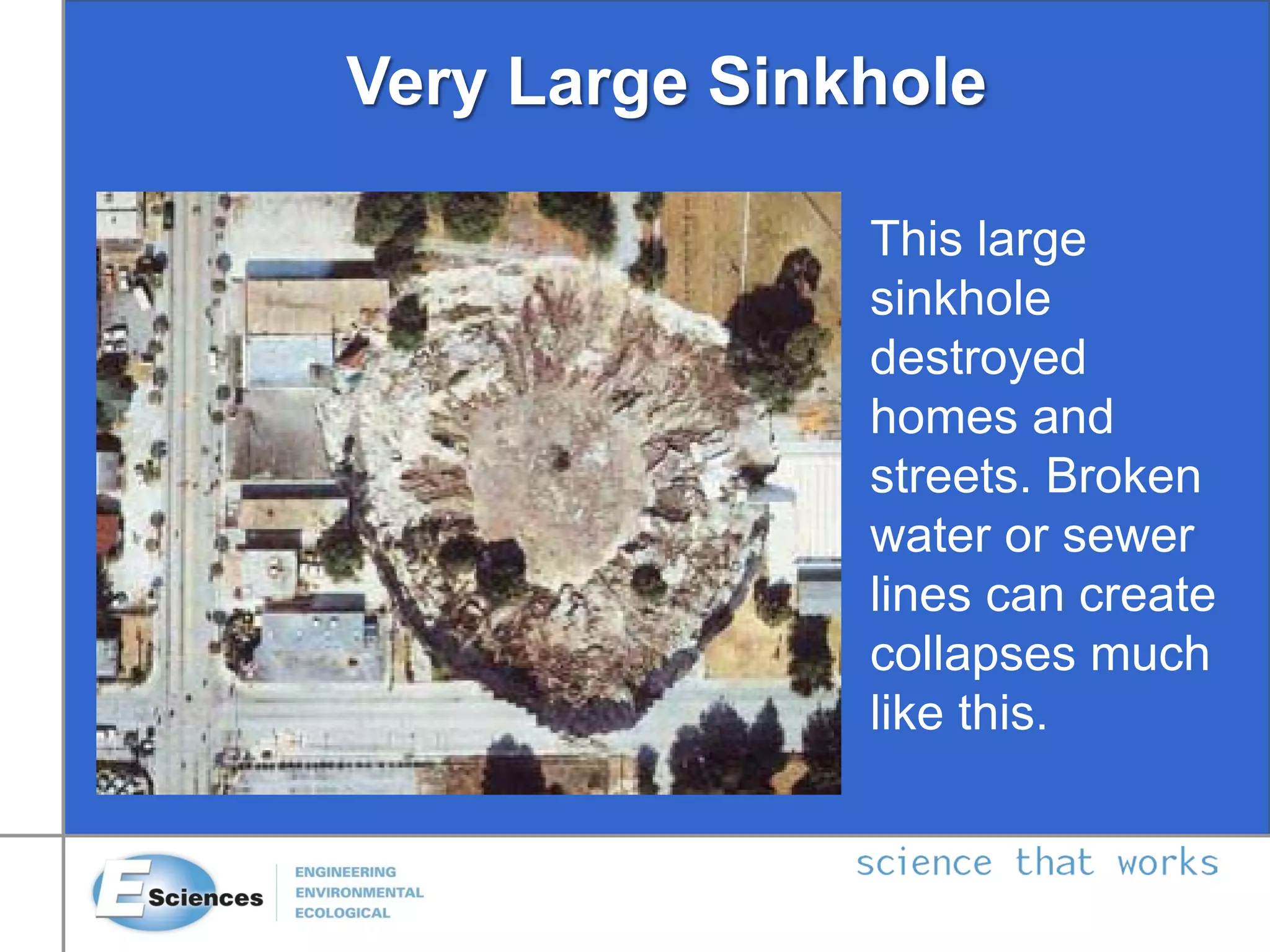
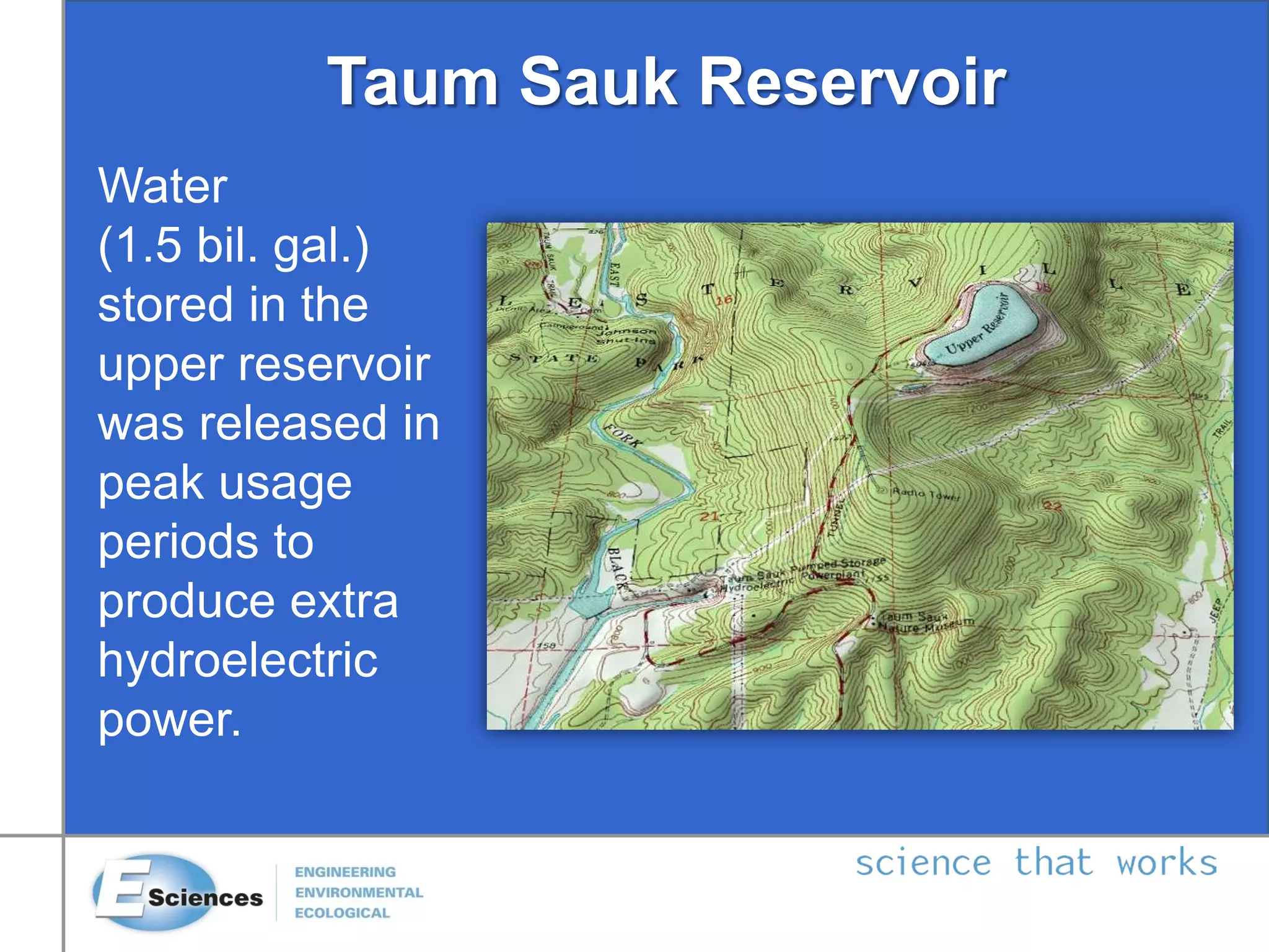

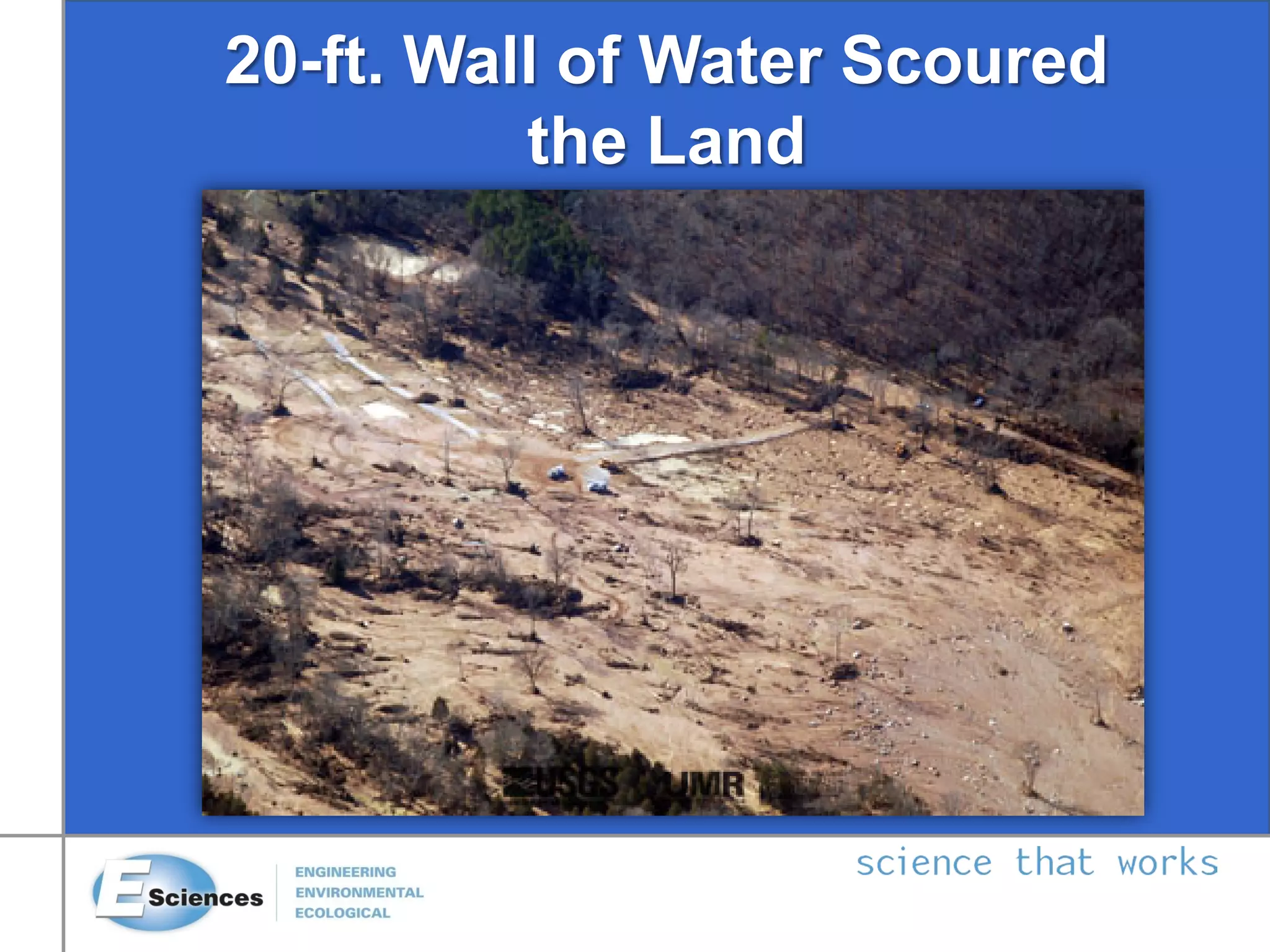


This document discusses various methods for stabilizing soils and improving ground conditions for public works projects. It describes causes of unconsolidated soils like water, clays, and organics. Key methods covered include soil cement, lime admixtures, flyash, dewatering, heating/freezing, vitrification, stone columns, deep dynamic compaction, drainage/surcharge, electro-osmosis, compaction grouting, blasting, surface compaction, vertical drains, jet grouting, soil nailing, tiebacks, shotcrete walls, underpinning, and dynamic compaction. The objectives, equipment used, and factors affecting different compaction and ground improvement techniques are also summarized.