1 | Pa g e
CHAPTER 1
SOIL IMPROVEMENT TECHNIQUES
For construction of foundations of buildings and other such structures, general practice is to use
shallow foundation if the soil close to the ground surface possesses sufficient bearing capacity.
However, where the top soil layer is either loose or soft, the load from the super structure has to be
transmitted to deeper strata. In such case, pier or pile foundations are used. There is also an alternate
method which may in case prove more economical than deep foundations. This alternate method is
called foundation soil improvement and ground modification. There are many methods by which
the soil at the site can be improved. Soil improvement is frequently termed as soil stabilization.
Sometimes the top layers of soil are undesirable and must be removed and replaced with better soil on
which the structural foundation can be built. The soil used as fill should be well compacted to sustain
the desired structural load. Compacted fills may also be required in low-lying areas to raise the ground
elevation for construction of the foundation. Soft saturated clay layers are often encountered at
shallow depths below foundations. Depending on the structural load and the depth of the layers,
unusually large consolidation settlement may occur. Special soil-improvement techniques are required
to minimize settlement.
Various techniques are used to:
ƒ Reduce the settlement of structures
ƒ Improve the shear strength of soil and thus increase the bearing capacity of shallow
foundations
ƒ Increase the factor of safety against possible slope failure of embankments and earth dams
ƒ Reduce the shrinkage and swelling of soils
Several soil improvement techniques are used such as:
ƒ Field Compaction
ƒ Vibroflotation
ƒ Vibro-rod
ƒ Blasting
ƒ Pre compression
ƒ Sand drains
ƒ Prefabricated Vertical Drains
ƒ Sand Compaction Piles
ƒ Dynamic Compaction
ƒ Stone Columns
ƒ Jet Grouting
ƒ Chemical Stabilization
ƒ Geotextile
ƒ Soil Nailing
ƒ Vacuum Consolidation of Soil
ƒ Soil Heating
ƒ Soil Freezing
2.
2 | Pa g e
FIELD COMPACTION
Any type of construction job which requires soil to be used as a foundation material or as a
construction material, compaction in-situ or in the field is necessary. The construction of a structural
fill usually consists of two distinct operations placing and spreading in layers and then compaction.
The first part assumes greater significance in major jobs such as embankments and earth dams where
the soil to be used as a construction material has to be excavated from a suitable borrow area and
transported to the work site. In this phase large earth moving equipment such as self-propelled
scrapers, bulldozers, grader sand trucks are widely employed. The phase of compaction may be
properly accomplished by the use of appropriate equipment for compaction. The thickness of layers
that can be properly compacted is known to berelated to the type of soil and method or equipment of
compaction. Generally speaking, granular soils can be adequately compacted in thicker layers than
fine-grained soils and clays; also, for a given soil type, heavy compaction equipment is capable of
compacting thicker layers than light equipment. Although the principle of compaction in the field is
relatively simple, it may turn out to be a complex process if the soil in the borrow area is not at the
desired optimum moisture content for compaction. The existing moisture content is to be determined
and water added, if necessary. Addition of water to the soil is normally done either during excavation
or transport tor rarely on the construction spot; however, water must be added before excavation in the
case of clayey soils. In case the soil has more moisture content than is required for proper compaction,
it has to be air-dried after excavation and compacted as soon as the desired moisture content is
attained.
Soil compaction or densification can be achieved by different means such as tamping action, kneading
action, vibration, and impact. Compactors operating on the tamping, kneading and impact principle
are effective in the case of cohesive soils, while those operating on the kneading, tamping and
vibratory principle are effective in the case of cohesionless soils.
The primary types of compaction equipment are: (i) rollers, (ii) rammers and (iii) vibrators.
Of these, by far the most common are rollers. Rollers are further classified as follows:
a) Smooth-wheeled rollers
b) Pneumatic- tyred rollers
c) Sheepsfoot rollers, and
d) Vibratory rollers
Vibrators are classified as:
a) Vibrating drum
b) Vibrating pneumatic tyre
c) Vibrating plate, and
d) Vibroflot
Rollers:
Smooth-wheel rollers (Figure 1.1) are suitable for proof rolling subgrades and for finishing operation
of fills with sandy and clayey soils. These rollers provide 100% coverage under the wheels, with
ground contact pressures as high as 310 to 380 kN/m2
(45 to 55lb/in2
). They are not suitable for
producing high unit weights of compaction when used on thicker layers.
Pneumatic rubber-tired rollers (Figure 1.2) are better in many respects than the smooth-wheel
rollers. The former are heavily loaded with several rows of tires. These tires are closely spaced—four
to six in a row. The contact pressure under the tires can range from 600 to 700 kN/m2
(85 to 100
lb/in2
), and they produce about 70 to 80% coverage. Pneumatic rollers can be used for sandy and
clayey soil compaction. Compaction is achieved by a combination of pressure and kneading action.
Sheepsfoot rollers (Figure 1.3) are drums with a large number of projections. The area of each
projection may range from 25 to 85 cm2 (4 to 13 in2
). These rollers are most effective in compacting
3.
3 | Pa g e
clayey soils. The contact pressure under the projections can range from 1400 to 7000 kN/m2
(200 to
1000 lb/in2). During compaction in the field, the initial passes compact the lower portion of a lift.
Compaction at the top and middle of a lift is done at a later stage.
Vibratory rollers (Figure 1.4) are extremely efficient in compacting granular soils. Vibrators can be
attached to smooth-wheel, pneumatic rubber-tired, or sheepsfoot rollers to provide vibratory effects to
the soil. The vibration is produced by rotating off-center weights.
Figure 1.1: Smooth-wheel roller
Figure 1.2: Pneumatic rubber-tired roller
Figure 1.3: Sheepsfoot roller
Figure 1.4: Vibratory rollers.
4.
4 | Pa g e
Rammers
This type includes the dropping type and pneumatic and internal commission type, which are also
called ‘FROG RAMMERS’ (Figure 1.5). They weigh up to about 1.5 kN (150 kg) and even as much
as 10kN (1t) occasionally. This type may be used for cohesionless soils, especially in small restricted
and confined areas such as beds of drainage trenches and back fills of bridge abutments.
Figure 1.5: From Rammer
Vibrators
These are vibrating units of the out-of-balance weight type or the pulsating hydraulic type. Such a
type is highly effective for cohesionless soils. Behind retaining walls where the soil is confined, the
backfill, much deeper in thickness, may be effectively compacted by vibration type of compactors.
A few of this type are dealt with below:
(a) Vibrating drum: A separate motor drives an arrangement of eccentric weights so as to cause a
high-frequency, low-amplitude, vertical oscillation to the drum. Smooth drums as well as sheepsfoot
type of drums may be used. Layers of the order of 1 meter deep could be compacted to high densities.
(b) Vibrating pneumatic tire: A separate vibrating unit is attached to the wheel axle. The ballast
box is suspended separately from the axle so that it does not vibrate. A 300 mm thick layer of granular
soil will be satisfactorily compacted after a few passes.
(c) Vibrating plate: This typically consists of a number of small plates, each of which is operated by
a separate vibrating unit. These have a limited depth of effectiveness and hence are used in
compacting granular base courses for highway and airfield pavements.
(d) Vibroflot: A method suited for compacting thick deposits of loose sandy soil is called the
‘vibroflotation’ process. The improvement of density is restricted to the surface zone in the case of
conventional compaction equipment. The vibroflotation method first compacts deep zone in the soil
and then works its way towards the surface. A cylindrical vibrator weighing about 20 kN (2 t) and
approximately 400 mm in diameter and 2 m long, called the ‘Vibroflot’, is suspended from a crane
and is jetted to the depth where compaction is to start.
The jetting consists of a water jet under pressure directed into the earth from the tip of the vibroflot; as
the sand gets displaced, the vibroflot sinks into the soil. Depths up to 12 m can be reached. After the
vibroflot is sunk to the desired depth, the vibrator is activated. The compaction of the soil occurs in
the horizontal direction up to as much as 1.5 m outward from the vibroflot. Vibration continues as the
vibroflot is slowly raised toward the surface. As this process goes on, additional sand is continually
dropped into the space around the vibroflot tofill the void created. To densify the soil in a given site,
locations at approximately 3-m spacingsare chosen and treated with vibroflotation.
The maximum dry density sought to be achieved in-situ is specified usually as a certain percentage of
the value obtainable in the laboratory compaction test. Thus control of compaction in the field
requires the determination of in-situ unit weight of the compacted fill and also the moisture content.
5.
5 | Pa g e
The methods available for the determination of in-situ unit weight are:
a) Sand-replacement method
b) Core-cutter method,
c) Volumenometer method,
d) Rubber balloon method,
e) Nuclear method,
f) Proctor plastic needle method.
Rapid methods of determination of moisture content such as the speedy moisture tester are adopted in
this connection. Some of the above aspects are dealt with in the following sub-sections.
VIBROFLOTATION
Vibroflotation is a technique developed in Germany in the 1930s for in situ densification of thick
layers of loose granular soil deposits. Vibroflotation was first used in the United States about 10 years
later. The process involves the use of a vibroflot (called the vibrating unit), as shown in figure 1.6 the
device is about 2 m in length. This vibrating unit has an eccentric weight inside it and can develop a
centrifugal force. The weight enables the unit to vibrate horizontally. Openings at the bottom and top
of the unit are for water jets. The vibrating unit is attached to a follow-up pipe. The figure shows the
vibroflotation equipment necessary for compaction in the field.
Figure 1.6: Vibrofloation unit
6.
6 | Pa g e
Advantages of Vibro Compaction Method:
¾ Reduction of foundation settlements.
¾ Reduction of risk of liquefaction due to seismic activity.
¾ Permit construction on granular fills.
The entire compaction process can be divided into four steps (see Figure 1.7):
Step 1. The jet at the bottom of the vibroflot is turned on, and the vibroflot is lowered into the ground.
Step 2. The water jet creates a quick condition in the soil, which allows the vibrating unit to sink.
Step 3. Granular material is poured into the top of the hole. The water from the lower jet is transferred
to the jet at the top of the vibrating unit. This water carries the granular material down the hole.
Step 4. The vibrating unit is gradually raised in about 0.3-m lifts and is held vibrating for about 30
seconds at a time. This process compact the soil to the desired unit weight.
Figure 1.7: Vibrofloation process
Table gives the details of various types of vibroflot unit used in the United States. The 23 kW electric
units have been used since the latter part of the 1940s. The 100-HP unitswere introduced in the early
1970s. The zone of compaction around a single probe will vary according to the type of vibroflot
used. The cylindrical zone of compaction will have a radius of about 2 m for a 23 kW unit and about 3
m for a 75 kW unit. Compaction by vibroflotation involves various probe spacings, depending on the
zone of compaction. In figure 1.7: Mitchell (1970) and Brown (1977) reported several successful
cases of foundation design that used vibroflotation.
Table: Types of Vibrating units
7.
7 | Pa g e
Figure 1.8: Number of probe spacing for vibrofloation.
The success of densification of in situ soil depends on several factors, the most important of which are
the grain-size distribution of the soil and the nature of the backfill used to fillthe holes during the
withdrawal period of the vibroflot. The range of the grain-size distribution of in situ soil marked Zone
1 in Figure 8 is most suitable for compaction by vibroflotation. Soils that contain excessive amounts
of fine sand and silt-size particles are difficult to compact; for such soils, considerable effort is needed
to reach the proper relative density of compaction. Zone 2 in Figure 1.9 is the approximate lower limit
of grain-size distribution for compaction by vibroflotation. Soil deposits whose grain-size distribution
falls into Zone 3 contain appreciable amounts of gravel. For these soils, the rate of probe penetration
may be rather slow, so compaction by vibroflotation might prove to be uneconomical in the long run.
Figure 1.9: Effective range of grain-size distribution of soil for vibroflotation
The grain-size distribution of the backfill material is one of the factors that control the rate of
densification. Brown (1977) defined a quantity called suitability number for rating a backfill material.
The SUITABILITY NUMBER is given by the formula
where and are the diameters (in mm) through which 50%, 20%, and 10%, respectively, of the material
is passing. The smaller the value of SN, more desirable is the backfill material. Following is a backfill
rating system proposed by Brown (1977):
8.
8 | Pa g e
VIBRO ROD SYSTEM
Figure 1.10: Vibro Wing system. Each pair of wing is oriented at a 1200
angle to those located
immediately above and below.
BLASTING
Blasting is a technique that has been used successfully in many projects (Mitchell,1970) for the
densification of granular soils. The general soil grain sizes suitable for compaction by blasting are the
same as those for compaction by vibroflotation. The process involves the detonation of explosive
charges such as 60% dynamite at ascertain depth below the ground surface in saturated soil. The
lateral spacing of the charges varies from about 3 to 9 m. Three to five successful detonations are
usually necessary to achieve the desired compaction. Compaction (up to a relative density of about
80%) up to a depth of about 18 m over a large area can easily be achieved by using this process.
9.
9 | Pa g e
Usually, the explosive charges are placed at a depth of about two thirds of the thickness of the soil
layer desired to be compacted. The sphere of influence of compaction by a 60% dynamite charge can
be given as follows(Mitchell, 1970):
Figure 10 shows the test results of soil densification by blasting in an area measuring 15 m by 9 m
(Mitchell, 1970). For these tests, twenty 2.09-kg charges of Gelamite No. 1 (Hercules Powder
Company, Wilmington, Delaware) were used.
Figure 1.11: Ground settlement as a function of number of explosive charges
Figure 1.12: Blasting using explosive.
10.
10 | Pa g e
PRELOADING OR PRECOMPRESSION
Preloading has been used for many years without change in the method or application to
improve soil properties. Preloading or pre-compression is the process of placing additional
vertical stress on a compressible soil to remove pore water over time. The pore water
dissipation reduces the total volume causing settlement. Surcharging is an economical
method for ground improvement. However, the consolidation of the soils is time dependent,
delaying construction projects making it a non-feasible alternative. The soils treated are
Organic silt, Varved silts and clays, soft clay, Dredged material The design considerations
which should be made are bearing capacity, Slope stability, Degree of consolidation.
Figure 1.13: Precompression using sand bag.
Applications of Preloading of Soil
¾ Reduce post-construction
¾ Settlement
¾ Reduce secondary compression.
¾ Densification
¾ Improve bearing capacity
The principles of precompression are best explained by reference to Figure 1.14. Here, the proposed
structural load per unit area is and the thickness of the clay layer undergoing consolidation is the
maximum primary consolidation settlement caused by the structural load is then
11.
11 | Pa g e
Figure 1.14: Principles of precompression
Figure 1.14 shows that, under a surcharge, the degree of consolidation U at time t2 after the
application of load is:
We get:
The degree of consolidation is used to determine t2, some construction problems might occur. The
reason is that, after the removal of the surcharge and placement of the structural load, the portion of
clay close to the drainage surface will continue to swell, and the soil close to the midplanewill
continue to settle. In some cases, net continuous settlement might result. A conservative approach
may solve the problem; that is, assume that U in Eq. is the mid plane degree of consolidation
(Johnson, 1970a). Now,
12.
12 | Pa g e
Figure 1.15: Plot of mid plane degree of consolidation against Tv
13.
13 | Pa g e
EXAMPLE 1
During the construction of a highway bridge, the average permanent load on the clay layer is expected
to increase by about 115 KN/m2
. The average effective overburden pressure at the middle of the clay
layer is 210 KN/m2
. Here Hc = 6 m, Cc = 0.28, Ղ= 0.9 and ܥ௩ = 0.36 m2
/mo. The clay is normally
consolidated. Determine
a. Total primary consolidation settlement of the bridge without pre compression.
b. The surcharge, ΔߪԢሺሻ, needed to eliminate entire primary consolidation settlement in
nine months by pre compression.
SOLUTION
The total primary consolidation settlement maybe calculated from:
ܵሺሻ =
ு
ଵାՂ
log [
௱ఙାఙᇱሺሻ
௱ఙ
] =
ሺǤଶ଼ሻሺሻ
ଵାǤଽ
Ž‘‰ ሾ
ଶଵାଵଵହ
ଶଵ
ሿ
= 0.1677 m = 167.7 mm
We have
ܶజ =
ഔ௧మ
ுమ
ܥజ = .36 m2
/mo.
H = 3 m (two way drainage)
ݐଶ ൌ ͻmo.
Hence,
ܶజ =
ሺǤଷሻሺଽሻ
ଷమ = 0.36
According to figure 14.19 for ܶజ = 0.36, the value of U is 47%. Now
ȟߪԢሺሻ= 115 KN/m2
And
ߪԢ= 210 KN /m2
So
ఙᇱሺሻ
௱ఙᇱ
=
ଵଵହ
ଶଵ
= 0.548
According to figure 14.17. For U is 47% ǡ ȟߪԢሺሻ/ ߂ߪԢ= 0.548,
ȟߪԢሺሻ/ ߂ߪԢሺሻ≈1.8;
ȟߪԢሺሻ= (1.8) (115) = 207 KN /m2
14.
14 | Pa g e
SAND DRAINS
The use of sand drains is another way to accelerate the consolidation settlement of soft, normally
consolidated clay layers and achieve precompression before the construction of a desired foundation.
Sand drains are constructed by drilling holes through the clay layer(s) in the field at regular intervals.
The holes are then backfilled with sand. This can be achieved by several means, such as (a) rotary
drilling and then backfilling with sand; (b) drilling by continuous-flight auger with a hollow stem and
backfilling with sand (through the hollow steam); and (c) driving hollow steel piles. The soil inside
the pile is then jetted out, after which backfilling with sand is done. Figure 1.16 shows a schematic
diagram of sand drains. After backfilling the drill holes with sand, a surcharge is applied at the ground
surface. The surcharge will increase the pore water pressure in the clay. The excess pore water
pressure in the clay will be dissipated by drainage both vertically and radially to the sand drains
thereby accelerating settlement of the clay layer. In Figure 1.16a, note that the radius of the sand
drains is rw Figure 1.16b shows the plan of the layout of the sand drains. The effective zone from
which the radial drainage will be directed toward a given sand drainis approximately cylindrical, with
a diameter of de.
Figure 1.16: Sand drains
Both radial and vertical drainage contribute to the average degree of consolidation. For a given
surcharge and duration, the average degree of consolidation due to drainage in the vertical and radial
directions is
15.
15 | Pa g e
Average Degree of Consolidation Due to Radial Drainage Only
Figure 1.17 shows a schematic diagram of a sand drain. In the figure, is the radius of the sand drain
and is the radius of the effective zone of drainage. It is also important to realize that, during the
installation of sand drains; a certain zone of clay surrounding them is smeared, thereby changing the
hydraulic conductivity of the clay. In the figure, the radial distance is from the center of the sand drain
to the farthest point of the smeared zone.
Figure 1.17: Schematic diagram of a sand drain
Now, for the average-degree-of-consolidation relationship, we will use the theory of equal strain. Two
cases may arise that relate to the nature of the application of surcharge, and they are shown in Figure
1.18. Either (a) the entire surcharge is applied instantaneously (see Figure 1.18a), or (b) the surcharge
is applied in the form of a ramp load (see Figure 1.18b).
Figure 1.18: Nature of application of surcharge
When the entire surcharge is applied instantaneously (Barron, 1948):
If the surcharge is applied in the form of a ramp and there is no smear, then (Olson, 1977)
16.
16 | Pa g e
and
Average Degree of Consolidation Due to Vertical Drainage Only:
Using Figure 1.18, for instantaneous application of a surcharge, we may obtain the average degree of
consolidation due to vertical drainage only. We have
And
Where, Uv = degree of consolidation due to vertical drainage only, and
Cv= Degree of consolidation for vertical drainage.
For the case of ramp loading, as shown in Figure 1.18, the variation of Uv with Tv can be expressed as
(Olson, 1977):
H = length of maximum vertical drainage path. Figure 1.19 shows the variation of with Uv(%) with
Tcand Tv.
Figure 1.19: Variation of Uv(%) with Tcand Tv.
17.
17 | Pa g e
Example 2
During the construction of a highway bridge, the average permanent load on the clay layer is expected
to increase by about 115 KN/m2
. The average effective overburden pressure at the middle of the clay
layer is 210 KN/m2
. Here Hc = 6 m, Cc = 0.28, Ղ= 0.9 and ܥ௩ = 0.36 m2
/mo. The clay is normally
consolidated. Determine If sand drain was used with ݎ௪= 0.1 m, ݀= 3m, ܥజ=ܥ௩௧, and the surcharge is
applied instantaneously. Determine the surcharge, Δ ߪԢሺሻ , needed to eliminate entire primary
consolidation settlement in nine months by pre compression. Assume that this is a no smear case.
Solution
From example 14.1, ܶజ= 0.36. Using equation (1.74), we obtain
ܶజ=
గ
ସ
[
ഔሺΨሻ
ଵ
ሿଶ
or,
ܷజ = ට
ሺସሻሺǤଷሻ
గ
*100 = 67.7%
Also,
n =
ௗ
ଶೢ
=
ଷ
ଶכǤଵ
= 15
Again,
ܶ =
ೡ௧మ
ௗమ
=
ሺǤଷሻሺଽሻ
ሺଷሻమ = .36
From table 14.5 for n= 15 and ܶ= 0.36, the value of ܷis about 77%, Hence,
ܷజǡ= 1 - (1- ܷజ ) (1 - ܷజ) = 1 - (1 - 0.67) ( 1 - 0.77 )
= 0.924 = 92.4 %
Now, from figure 14.17, for ȟߪԢሺሻ/ ߂ߪԢ= 0.548 and ܷజǡ = 92.4 %, the value of ȟߪԢሺሻ/ ߂ߪԢሺሻ=
0.12, Hence,
ȟߪԢሺሻ= (115) (0.12) = 13.8 KN/ʹ
Methods of Installation of Sand Drain:
1. High pressure water jetting
2. Displacement of the natural ground
3. Wash boring with auger
18.
18 | Pa g e
1. High pressure water jetting
2. Displacement of the natural ground
3. Wash boring with auger
19.
19 | Pa g e
WICK DRAINS (PREFABRICATED VERTICAL DRAINS)
Prefabricated vertical drains (PVDs), also referred to as wick or strip drains, were originally
developed as a substitute for the commonly used sand drain. With the advent of materials science,
these drains began to be manufactured from synthetic polymers such as polypropylene and high-
density polyethylene. PVDs are normally manufactured with a corrugated or channeled synthetic core
enclosed by a geotextile filter, as shown schematically in Figure 1.20.Installation rates reported in the
literature are on the order of 0.1 to 0.3 excluding equipment mobilization and setup time. PVDs have
been used extensively in the past for expedient consolidation of low-permeability soils under surface
surcharge. The main advantage of PVDs over sand drains is that they do not require drilling; thus,
installation is much faster. Figures 1.22 are photographs of the installation of PVDs in the field.
Figure 1.20: Prefabricated vertical drain Figure 1.21:
Figure 1.22: Installation of Prefabricated vertical drain
21 | Pa g e
EXAMPLE 4:
STONE COLUMNS
A method now being used to increase the load-bearing capacity of shallow foundations on soft clay
layers is the construction of stone columns. This generally consists of water-jettinga vibroflot into the
soft clay layer to make a circular hole that extends through the clay to firmer soil. The hole is then
filled with imported gravel. The gravelin the hole is gradually compacted as the vibrator is withdrawn.
The gravel used for the stone column has a size range of 6 to 40 mm. Stone columns usually have
diameters of 0.5to 0.75 m and are spaced at about 1.5 to 3 m center to center. Figure 1.23 shows the
construction of a stone column. After stone columns are constructed, a fill material should always be
placed over the ground surface and compacted before the foundation is constructed. The stone
columns tend to reduce the settlement of foundations at allowable loads.
22.
22 | Pa g e
Figure 1.23: Installation of Stone column
Stone columns work more effectively when they are used to stabilize a large area where the undrained
shear strength of the subsoil is in the range of 10 to than to improve the bearing capacity of structural
foundations (Bachus and Barksdale,1989). Sub soils weaker than that may not provide sufficient
lateral support for the columns. For large-site improvement, stone columns are most effective to a
depth of 6to 10 m. However, they have been constructed to a depth of 31 m.
SAND COMPACTION PILE
Sand compaction piles are similar to stone columns, and they can be used in marginal sitesto improve
stability, control liquefaction, and reduce the settlement of various structures. Built in soft clay, these
piles can significantly accelerate the pore water pressure-dissipation process and hence the time for
consolidation.
Sand compaction piles are constructed by driving a hollow mandrel with its bottom closed during
driving. On partial withdrawal of the mandrel, the bottom doors open. Sand is poured from the top of
the mandrel and is compacted in steps by applying air pressure as the mandrel is withdrawn. The piles
are usually 0.46 to 0.76 m in diameter and are placed at about 1.5 to 3 m center to center. The pattern
of layout of sand compaction piles is the same as for stone columns. Figure 1.24 shows the
construction of sand compaction piles.
23.
23 | Pa g e
Figure 1.24: Sand compaction pile installation
DYNAMIC COMPACTION
Dynamic compaction is a technique that is beginning to gain popularity in the United States for
densification of granular soil deposits. The process primarily involves dropping a heavy weight
repeatedly on the ground at regular intervals. The weight of the hammer used varies from 8 to 35
metric tons, and the height of the hammer drop varies between 7.5 and 30.5 m.
The stress waves generated by the hammer drops help in the densification. The degree of compaction
achieved depends on
ƒ The weight of the hammer
ƒ The height of the drop
ƒ The spacing of the locations at which the hammer is dropped
Leonards et al. (1980) suggested that the significant depth of influence for compaction is
approximately
24.
24 | Pa g e
Figure 1.25: Dynamic Compaction
JET GROUTING
Jet grouting proves its effectiveness across wide range of soils. It is an erosion-based system. Granular
soils are considered the most erodible and plastic clays the least. The technique hydraulically mixes
soil with grout to create in situ geometries of soilcrete. Hydraulic Rotary drill is used to reach the
design depth and at that point grout and sometimes water and air are pumped to the drill rig. This
create a cementitious soil matrix called soilcrete.
Figure 1.26: Jet Grouting
25.
25 | Pa g e
There are three traditional jet grout systems:
• The single-fluid system: A high-velocity cement slurry grout is used to erode and mix the soil. This
system is most effective in cohesion less soil
• The double-fluid system: The high-velocity cement slurry jet is surrounded with an air jet. The
shroud of air increases the erosion efficiency. The double-fluid system is more effective in cohesive
soils than the single-fluid system.
• The triple-fluid system: A high-velocity water jet surrounded by an air jet is used to erode the soil.
A lower jet injects the cement slurry at a reduced pressure. Separating the erosion process from the
grouting process results in higher quality soilcrete and is the most effective system in cohesive soils.
Figure 1.27: Different types of Jet Grouting System
CHEMICAL STABILIZATION
The physical properties of soils can often economically be improved by use of chemical admixtures.
Some of more widely used admixtures include lime, cement and fly ash. The process of soil
stabilization first involves mixing with the soil a suitable additive which changes its property and then
compacting the admixture suitably. The method is applicable only for the soils in shallow foundations
or the base course of roads.
LIME STABILIZATION
Lime stabilization improves the strength, stiffness and durability of fine grained materials. Lime has
been used as a stabilizer for soils in the base courses of pavement system, under concrete foundation,
on embankment slopes and canal linings. Adding lime to soil produces a maximum density under
higher optimum moisture content than in the untreated soil. Moreover, lime produces a decrease in
plasticity index. Lime stabilization has been extensively used to decrease swilling potential and
swilling pressure in clays.
The types of lime commonly used to stabilize fine-grained soils are hydrated high-calcium lime
[Ca(OH)2], calcitic quicklime (CaO), monohydrated dolomitic lime [Ca(OH)2.MgO] and dolomitic
quicklime. The quantity of lime used to stabilize most soils usually is in the range from 5 to 10%.
When lime is added to clayey soils, two pozzolanic chemical reactions occur: cation exchange and
flocculation–agglomeration. In the cation exchange and flocculation–agglomeration reactions, the
monovalent cations generally associated with clays are replaced by the divalent calcium ions. The
cations can be arranged in a series based on their affinity for exchange:
26.
26 | Pa g e
Any cation can replace the ions to its right. For example, calcium ions can replace potassium and
sodium ions from a clay. Flocculation–agglomeration produces a change in the texture of clay soils.
The clay particles tend to clump together to form larger particles, thereby (a) decreasing the liquid
limit, (b) increasing the plastic limit, (c) decreasing the plasticity index, (d) increasing the shrinkage
limit, (e) increasing the workability, and(f) improving the strength and deformation properties of a
soil.
Pozzolanic reaction between soil and lime involves a reaction between lime and the silica and alumina
of the soil to form cementing material. One such reaction is
Lime stabilization in the field can be done in three ways. They are
1. The in situ material or the borrowed material can be mixed with the proper amount of lime at
the site and then compacted after the addition of moisture.
2. The soil can be mixed with the proper amount of lime and water at a plant and then hauled
back to the site for compaction.
3. Lime slurry can be pressure injected into the soil to a depth of 4 to 5 m.
Figure 1.28: Lime stabilization in the field
CEMENT STABILIZATION
Cement is being increasingly used as a stabilizing material for soil, particularly in the construction of
highways and earth dams. The first controlled soil–cement construction in the United States was
carried out near Johnsonville, South Carolina, in 1935. Cement can be used to stabilize sandy and
clayey soils. As in the case of lime, cement helps decrease the liquid limit and increase the plasticity
index and workability of clayey soils. Cement stabilization is effective for clayey soils when the
liquid limit is less than 45 to 50 and the plasticity index is less than about 25.
Like lime, cement helps increase the strength of soils, and strength increases with curing time.
Granular soils and clayey soils with low plasticity obviously are most suitable for cement
stabilization. Calcium clays are more easily stabilized by the addition of cement, whereas sodium and
hydrogen clays, which are expansive in nature, respond better to lime stabilization. For these reasons,
proper care should be given in the selection of the stabilizing material.
Similar to lime injection, cement slurry made of portland cement and water (in a water–cement ratio
of 0.5:5) can be used for pressure grouting of poor soils under foundations of buildings and other
structures. Grouting decreases the hydraulic conductivity of soils and increases their strength and
load-bearing capacity. For the design of low-frequency machine foundations subjected to vibrating
27.
27 | Pa g e
forces, stiffening the foundation soil by grouting and thereby increasing the resonant frequency is
sometimes necessary.
Figure 1.29: Cement stabilization in the field
FLY-ASH STABILIZATION
Fly ash is a by-product of the pulverized coal combustion process usually associated with electric
power-generating plants. It is a fine-grained dust and is composed primarily of silica, alumina, and
various oxides and alkalies. Fly ash is pozzolanic in nature and can react with hydrated lime to
produce cementitious products. For that reason, lime–fly-ash mixtures can be used to stabilize
highway bases and sub bases. Effective mixes can be prepared with 10 to 35% fly ash and 2 to 10%
lime. Soil–lime–fly-ash mixes are compacted under controlled conditions, with proper amounts of
moisture to obtain stabilized soil layers.
A certain type of fly ash, referred to as “Type C” fly ash, is obtained from the burning of coal
primarily from the western United States. This type of fly ash contains a fairly large proportion (up to
about 25%) of free lime that, with the addition of water, will react with other fly-ash compounds to
form cementitious products. Its use may eliminate the need to add manufactured lime.
Figure 1.30: Fly Ash stabilization in the field
28.
28 | Pa g e
GEOTEXTILE:
Soil alone is strong enough in compression but comparatively weak in tension. Reinforcing soil is the
technique where tensile elements are placed in the soil to improve stability and control deformation.
The geotextiles are used as reinforcement, their prime role is to provide tensile strength to soil at strain
level which is compatible with the performance of the soil structure. Textiles are used as reinforcement
in the form of fibers, fabric form like woven, knitted, non wovens. Geosynthetics are used as
reinforcement in paved roads, in railway tracks, embankment of shallow weak soils, earth retaining
walls, mining subsidence protection etc. This papers deals with the different types of geosynthetics
which are majorly used in reinforecement of soil, so that the soil gets stabilized and the problems like
erosion can be controlled.
Different Categories of Geosynthetics
1. Geotextiles- These are flexible textile fabrics of controlled permeability used to provide
filtration, separation or reinforcement in soil, rock and waste material.
2. Geomembranes- These are impermeable polymeric sheets used as carrier for liquid or solid
waste containment.
3. Geogrids- Stiff or flexible polymer grid like sheets with large aperture used primarily as
reinforcement of unusable soil and waste masses.
4. Geonets- stiff polymer net like sheets with in plane opening used primarily as a drainage
materials within landfills or soil and rock masses.
5. Geosynthetic clay liners- prefabricated bentonite clay layers incorporated between geotextile
and geomembrane and used as a barrier for liquid or solid waste containment.
6. Geopipes- Perforated or solid wall polymeric pipes used for the drainage of various liquids.
7. Geocomposites- Hybrid systems of anyor all the above geosynthetics types which can function
as specifically designed for use in soil, rock, waste and liquid related problems.
8. Geofoam- A newer category of product is geofoam. Which is the generic name for any foam
material utilized for geotechnical application. Geofoam is manufactured into large blocks which
are stacked to form a light weight thermally insulating mass buried within a soil or pavement
structure.
Figure 1.31: Geocells
29.
29 | Pa g e
Different Types of Geotextiles
1. WOVEN GEOTEXTILES: Woven geotextiles are manufactured from by adopting technique
similar to clothing textiles. This type has characteristic appearance of two stes of parallel threads
or yarns.They have a surprisingly wide range of applications and they are used in lighter weight
form as soil separators, filters and erosion control textiles. In heavy weights, they are used for soil
reinforcement in steep embankments and vertical soil walls; the heavier weight products also tend
to be used for the support of embankments built over soft soils. The beneficial property of the
woven structure in terms of reinforcement, is that stress can be absorbed by the warp and weft
yarns and hence by fibres, without much mechanical elongation. This gives them a relatively high
modulus or stiffness.
2. NON-WOVEN GEOTEXTILES – Non-woven geotextiles can be manufactured from either
short staple fibres or continuos filaments. The fibers can be bonded together by adopting thermal,
chemical or mechanical techniques or a combination of techniques. The type of fibre (staple or
continuous) used has very little effect on the properties of the non – woven geo synthetics. Non-
woven geotextiles are manufactured through a process of mechanical interlocking or chemical or
thermal bonding of fibres/filaments.
3. KNITTED GEOTEXTILES – knitted geosynthetics are manufactured using another process
which is adopted from clothing textiles industry. In this process, interlocking a series of loops of
yarn together is made. The majority of knitted geosynthetics made from polypropylene
polyester fibres. Knitted fabrics, as used in the field of geotextiles, are restricted to warp-knitted
textiles, generally specially produced for the purpose.Warp-knitting machines can produce fine
filter fabrics,medium meshes and large diameter soil reinforcing grids. However, it is generally
found that only the high strength end of the product range is cost effective, usually for soil
reinforcement and embankment support functions.
Figure 1.32: a. Woven geotextilesb. Non-woven geotextiles c. Knitted geotextiles
How geotextile functions as reinforcement in soil
Load on the soil produces expansion. Thus, under load at the interface between the soil and
reinforcement (assuming no slippage occurs, i.e. there is sufficient shear strength at the soil/fabric
interface). These two materials must experience the same extension, producing a tensile load in each
of the reinforcing elements that in turn is redistributed in the soil as an internal confining stress. Thus
the reinforcement acts to prevent lateral movement because of the lateral shear stress developed.
Hence, there is an inbuilt additional lateral confining stress that prevents displacement. This method
of reinforcing the soil can be extended to slopes and embankment stabilisation.
30.
30 | Pa g e
Strength created by the introduction of geotextile into the soil developed primarily through the
following three mechanisms-
1. Lateral restraint through interfacial friction between geotextile and soil/aggregate.
2. Forcing the potential bearing surface failure plane to develop at alternate higher shear
strength surface.
3. Membrane type of support of the wheel load
The structural stability of the soil is greatly improved by the tensile strength of the geosynthetic
material. This concept is similar to that of reinforcing steel to the concrete. Since concrete is weak in
strength tension, reinforcing steel is used to strengthen it. Geotextile materials function in a similar
manner as the reinforcing steel by providing strength that helps to hold the soil in place.
Reinforcement provided by the geotextiles and geogrids allow embankment roads to be built over
very weak soils allows for steeper embankments to be built.
Steep faced embankment reinforcement using geosynthetics
To construct a very steep slope at an angle at an inclination of 75 0 or more to the horizontal, then the
structure would be more akin to an inclined retaining wall. The stress concentration beneath the steep
faced embankment usually precludes their use over soft deposite. With reinforced embankment slope
above or near to the natural angle of repose of the fill careful thought must be given to the surface
finish. If the geotextile grid with an aperture size greater than the diameter of the fill particles is used,
then the geptextile filer sheet should also be palced behind the reinforcemment grid at slope face.
Usually the face will be covered with top soil seeded. The wrap-around method envolve folding the
geotextile over the exposed slope edge upto the underside of the next reinforcement layer as per the
required angle then anchoring the free end by burial within the fill.
Figure 1.33: Reinforced slope during construction and finished project
Geotextile are also used for better compaction of the fill. This application is particularly well
established for railway embankment in japan. As railway embankments are relatively narrow
incomparison with highway embankment, it follows that greater proportion of the embankment will
suffer from impaired compaction in the case of railway embankment. The climatic seismic
conditions in the japan make poorly compacted embankments faces susceptible to surface movement
erosion. On the uestu railway in japan, it was found that the presence of geogrid within the
embankment enhanced both the degree of compaction stiffness of the soil.
31.
31 | Pa g e
Figure 1.34: Collapsed railway embankment after loading and Geogrid-reinforcement railway
embankment
Subgrade stabilization base reinforcement using geotextiles in roads:
A large variety of detrimental factors affect the service life of roads and pavements including
environmental factors, subgrade conditions, traffic loading, utility cuts, road widenings, and aging.
The four main applications for geosynthetics in roads are subgrade separation and stabilization, base
reinforcement, overlay stress absorption and overlay reinforcement. Subgrade stabilization and base
reinforcement involve improving the road structure as it is constructed by inserting an appropriate
geosynthetic layer. Subgrade separation and stabilization applies geosynthetics to both unpaved and
paved roads. Base reinforcement is the use of geosynthetics to improve the structure of a paved road.
Permanent roads carry larger traffic volumes and typically have asphalt or portland cement concrete
surfacing over a base layer of aggregate. The combined surface and base layers act together to support
and distribute traffic loading to the subgrade. Problems are usually encountered when the subgrade
consists of soft clays, silts and organic soils. This type of subgrade is often water sensitive and, when
wet, unable to adequately support traffic loads. If unimproved, the subgrade will mix with the road
base aggregate – degrading the road structure - whenever the subgrade gets wet. The geotextiles used
for reinforcement of road can be natural or synthetic. The natural geotextile e.g. jute geotxtiles,
whereas the synthetic includes synthetic geotextiles geogrids, geonet, Geosynthetic clay liners etc.
In paved roads, lateral restraint called confinement is considered to be the primary function of the
geosynthetic. With the addition of an appropriate geosynthetic, the Soil-Geosynthetic- Aggregate
(SGA) system gains stiffness. The stiffened SGA system is better able to provide the following
structural benefits:
1. Preventing lateral spreading of the base.
2. Increasing confinement and thus stiffness of the base.
3. Improving vertical stress distribution on the subgrade.
4. Reducing shear stress in the subgrade.
Figure 1.35: Load Spreading phenomenon of sub-base on sub-grade
32.
32 | Pa g e
Application of geosynthetics in rail track stabilization:
Geosynthetics have been used in various ways in new rail tracks and track rehabilitation for almost
three decades. When appropriately designed and installed, geosynthetics provide a cost-effective
alternative to more traditional techniques. There are several problems required to be corrected in
railway tracks, increasing the bearing capacity of the subgrade soil, preventing contamination of the
ballast by subgrade fines, and dissipating the high pore water pressures built up by cyclic train
loading. The woven fabrics or non-wovens are used to separate the soil from the sub-soil without
impeding the ground water circulation where ground is unstable. Enveloping individual layers with
fabric prevents the material wandering off sideways due to shocks and vibrations from running trains.
Maintaining track bed geometry is critical for efficient railroad operation. Subgrade pumping into the
overlying ballast can create an uneven track bed, resulting in delayed arrivals and even derailments.
Geotextiles perform multiple functions in railroad applications. Nonwoven fabrics are used to
stabilize both new and rehabilitated tracks. They prevent contamination of new ballast with
underlying fine-grained soils and provide a mechanism for lateral water drainage. Using nonwoven
geotextiles beneath track beds ensures that the ballast can sustain the loads for which it was designed.
These geotextiles are used in all track applications, including switches, turnouts and grade crossings.
High-strength woven geotextiles can also be used to reinforce weak subgrade soils and reduce
required embankment fill materials.
Figure 1.36: Placement of geotextile under railway track
Discussed the physical and mechanical properties of ballast that affect the performance of railtracks.
The results of cyclic tests on ballast, based on large-scale cylindrical triaxial testing, indicate that the
ballast particle size distribution has a significant influence on ballast degradation, with the uniformly
graded distribution being the most prone to breakage. The findings of this study suggest that the
deformations of fresh and recycled ballast vary non-linearly with the number of load cycles.
Irrespective of the type of ballast, reinforcement and saturation, the settlement of ballast stabilizes
within about100000 loadcycles. The experimental results of this study clearly showed that with the
insertion of any type of selected geosynthetics the extent of degradation and settlement in fresh and
recycled ballast were reduced. It is also recommended that a bonded geosynthetics be employed
because of the need to prevent the ingress of liquefied mud into ballast voids under cyclic loads, and
to maintain an efficient pore pressure dissipation layer. The effectiveness of geosynthetics in
improving fresh ballast behavior (deformation and degradation) was marginal, whereas it was more
evident when used with recycled ballast in wet or dry conditions. According to the results, the
inclusion of geocomposites in recycled ballast reduces the breakage index almost to that of fresh
ballast (without geosynthetics). Hence the use of recycled ballast stabilized with geosynthetics would
be a cost-effective and environmentally attractive option. The ballast and its engineering behavior
have a key role in governing the stability and performance of railway tracks.
33.
33 | Pa g e
Soil reinforcement for Rainfall erosion control:
On steep ground with little or no covering of vegetation, rainfall erosion can be a major problem.
Erosion-susceptible slopes may occur naturally, for instance where vegetation is unable to become
established because of poor or very thin topsoil, or where vegetation is suddenly removed by a forest
fire.
Figure 1.37: Soil reinforcement for Rainfall erosion control
A. Surface cover geotextiles: The surface cover geotextiles are providing temporary cover over the
soil surface which dissipates the raindrop impact energy in a similar manner to foliage. Erosion
control geotextiles currently available are in two different forms:
1. Paper strips held together by a knitted polymer yarn .They are placed over the ground surface after
seeding and should ideally decompose sufficiently for the seedlings to push through shortly after
germination. The paper strip geotextile sheet is normally anchored at the top of the slope by burial in a
trench.
2. Woodwool sandwiched between two layers of polymer net.The woodwool geotextile are consists of
shredded pine wood and have a weight of about 0.5 kg/m2. The outer netting is often made from
0.2mm diameter polypropylene yarn with a typical aperture size of about 35*25 mm. The greater
selfweight of the woodwool geotextile and the interlocking action of plant shoots growing into the
tangled woodwool also make it less vulnerable to being pushed up by seedlings. As well as protection
against raindrop impact, woodwool geotextiles act as a thick blanket with many of the attributes of a
conventional mulch, namely:
ƒ Limiting the speed of any rainfall run-off.
ƒ Reducing the evaporation from the soil.
ƒ Protecting germinating seeds from extremes in temperature. There geotextiles also provide
protection against wind erosion, making then suitable for coastal same dunes.
B. Surface reinforcement geotextiles: Surface reinforcement geotextilesfunctions in a similar
manner to plant roots by reinforcing the soil surface holding the soil particles together. Unlike
surface cover geotextiles, geotextile mats are seeded after the geotextile has been laid. Another
difference is that the sheet of geotextile mats are usually unrolled shallow slow, rather than laid
parallel to the ground contours. After the geotextile mat has been secured on the ground surface,
seed(usually grass) is sown through the mat mixture of topsoil seed then brushed over the mat to
completely feel it. The celluler geotextiles are used for reinforcing the topsoil layer. The cellular
34.
34 | Pa g e
geotextile is formed from a mechanically bonded nonwoven products which has been partially
impregnated with resin in order to give it slight rigidity.
The four main sub-divisions of surface reinforcement geotextiles are:
1. Thick three dimensional mats
2. Cellular geotextiles
3. Geotextileswoven from thick, widely spaced yarns
4. High profile geotextiles nets.
Geo textiles for reinforcement of retaining walls:
Retaining walls help to maximize their land use. However, building a concrete gravity or crib wall is
often impractical because of their high construction cost. Geotextiles are used for a wide assortment
of reinforcement applications, including embankments over soft soils, levees and retaining walls.
Geotextiles are well-suited to construction of walls with timber, precast panel and segmental block
facing. In fact a geotextile retaining wall can be built for less than half the cost of a conventional wall.
Woven geotextiles offer other significant advantages over conventional methods, such as simplified
installation and construction, and the ability to use on-site backfill material. Polypropylene geotextiles
cost approximately half the amount of polyester and polyethylene geogrids, and they require
considerably less labor to install.
Figure 1.38: Geo textiles for reinforcement of retaining walls
35.
35 | Pa g e
SOIL NAILING
The fundamental concept of soil nailing consists of reinforcing the ground by passive
inclusions, closely spaced, to create in-situ soil and restrain its displacements. The basic
design consists of transferring the resisting tensile forces generated in the inclusions into the
ground through the friction mobilized at the interfaces.
Applications of Soil Nailing Technique:
¾ Stabilization of railroad and highway cut slopes
¾ Excavation retaining structures in urban areas for high-rise building and underground
facilities
¾ Tunnel portals in steep and unstable stratified slopes
¾ Construction and retrofitting of bridge abutments with complex boundaries involving wall
support under piled foundations
Figure 1.39: Soil Nailing
36.
36 | Pa g e
VACUUM CONSOLIDATION OF SOIL
Vacuum Consolidation is an effective means for improvement of saturated soft soils. The
soil site is covered with an airtight membrane and vacuum is created underneath it by using
dual venture and vacuum pump. The technology can provide an equivalent pre-loading of
about 4.5m high conventional surcharge fill. Vacuum-assisted consolidation preloads the
soil by reducing the pore pressure while maintaining a constant total stress.
Figure 1.40: Vacuum consolidation of soil
Applications of Vacuum Consolidation of Soil:
¾ Replace standard preloading techniques eliminating the risk of failure.
¾ Combine with a water preloading in scare fill area. The method is used to build
large developments on thick compressible soil.
¾ Combine with embankment pre-load using the increased stability
SOIL REPLACEMENT
Soil replacement is one of the oldest and simplest methods which improve the bearing soil conditions.
The foundation condition can be improved by replacing poor soil (eg. organic soils and medium or
soft clay) with more competent materials such as sand, gravel or crushed stone as well, nearly any soil
can be used in fills. However, some soils are more difficult to compact than others when used as a
replacement layer. The use of replacement soil under shallow foundation can reduce consolidation
settlement and increase soil bearing capacity. It has some advantages over other techniques and deep
foundation as it is more economical and requires less delay to construction. Despite of soil
replacement's advantages, the determination of the replacement soil thickness is based on experience
which in many cases is questionable. P.C.Varghese stated that the region of high stress in a shallow
foundation is only 1 to 1.5 its breadth and this part can be replaced by selected good soil. Abdel Salam
and Abdel Fatah investigated the effect of using different types and thickness of replacement layer on
increasing bearing capacity and reducing consolidation settlement of soft clayey soil experimentally
and concluded that, with increasing replacement layer thickness the vertical settlement decreased.
37.
37 | Pa g e
Figure 1.41: Soil replacement
SOIL HEATING
Raj Stated that the higher the heat input per mass of soil being treated, the greater the effect. Even
small increase in temperature may cause strength increase in fine grained soils by reducing the electric
repulsion between the particles, a flow of pore water due to thermal gradient and a reduction in
moisture content because of increasing evaporation rate. Table shows the effect of increasing the
temperature on changing soil properties.
Heating is applied to the soil by burning liquid or gas fuels in boreholes or injection of hot air into
0.15 to 0.2 m diameter boreholes that can preduce 1.3 to 2.5 m diameter stabilized zone after
continous treatment for about 10 days. This techniques can be effectively used when a large and
inexpensive heat source is located near the site.
Figure 1.42: Soil Heating
38.
38 | Pa g e
SOIL FREEZING
Soil freezing involves lowering the temperature of the soil until the moisture in the pore spaces
freezes. Freezing of pore water acts as a cementing agent between the soil particles causing significant
increase in shear strength and permeability. Unlike soil heating, soil freezing may be applicable to a
wide range of soil types, grain sizes and ground conditions. Fundamentally, the only requirement is
that the ground has sufficient soil moisture (pore water). The process typically involves installing
double walled pipes in the soil. A coolant is circulated through a closed circuit. A refrigeration plant is
used to maintain the coolant’s temperature.
Applications of Ground Freezing Technique
¾ Temporary underpinning
¾ Temporary support for an excavation
¾ Prevention of groundwater flow into excavated area
¾ Temporary slope stabilization
¾ Temporary containment of toxic/hazardous waste contamination
¾
Figure 1.43: Ground Freezing
39.
39 | Pa g e
C
CHAPTER 2
DRILLED PIER, CAISSON AND COFFERDAM
DRILLED PIERS
A drilled pier is a large diameter concrete cylinder built in the ground. The construction of a drilled
pier, a large diameter hole is drilled in the ground and subsequently filled with concrete. The
difference between drilled pier and bored pile is basically of size. Generally, bored piles are of
diameter less than or equal to 0.6m. The shafts of size large than 0.6m are generally designated as
drilled pier. A drilled pier is a type of deep foundation constructed to transfer heavy axial or lateral
loads to a deep stratum bellow ground surface.
Advantages:
The use of drilled-shaft foundations has several advantages:
1. A single drilled shaft may be used instead of a group of piles and the pile cap.
2. Constructing drilled shafts in deposits of dense sand and gravel is easier than driving piles.
3. Drilled shafts may be constructed before grading operations are completed.
4. When piles are driven by a hammer, the ground vibration may cause damage to nearby
structures. The use of drilled shafts avoids this problem.
5. Piles driven into clay soils may produce ground heaving and cause previously driven piles to
move laterally. This does not occur during the construction of drilled shafts.
6. There is no hammer noise during the construction of drilled shafts; there is during pile
driving.
7. Because the base of a drilled shaft can be enlarged, it provides great resistance to the uplifting
load.
8. The surface over which the base of the drilled shaft is constructed can be visually inspected.
9. The construction of drilled shafts generally utilizes mobile equipment, which, under proper
soil conditions, may prove to be more economical than methods of constructing pile
foundations.
10. Drilled shafts have high resistance to lateral loads.
Disadvantages:
There are some disadvantages too:
1. Installation of drilled piers needs a careful supervision and quality control of all materials
used in the construction.
2. The concreting operation may be delayed by bad weather.
3. It needs sufficient storage space for all the materials used in the construction.
4. Construction of drilled piers at places where there is a heavy current of flow of ground water
flow due to artesian pressure is very difficult.
5. In the case of braced cuts, deep excavations for drilled shafts may induce substantial ground
loss and damage to nearby structures.
0.6m. shafts
tratum b
grading operations
ground heaving
uplifting
oad.
artesian pressure
braced cuts, substantial ground
loss
40.
40 | Pa g e
TYPES OF DRILLED SHAFTS
Drilled piers may be described under four types. All four types are similar in construction technique,
but differ in their design assumptions and in the mechanism of load transfer to the surrounding earth
mass. These types are illustrated in figure 2.1:
1. Straight-shaft end-bearing piers: developed their support from end-bearing on strong soil,
“hardpan” or rock. The overlying soil is assumed to contribute nothing to the support of the
load imposed on the pier.
2. Straight-shaft side wall friction piers pass through overburden soils that are assumed to carry
none of the load, and penetrate far enough into an assigned bearing stratum to develop design
load capacity by side wall friction between the piers and bearing stratum.
3. Combined straight shaft side wall friction and end bearing piers are of the same construction
as the two mentioned above, but with both side wall friction and end bearing assigned a role
in carrying the design load.
4. Belled or under reamed piers with a bottom bell or under ream. A greater percentage of the
imposed load on the pier top is assumed to be carried by the base.
Figure 2.1: Types of drilled pier and underream shapes: a) Straight-shaft end-bearing piers
b) Straight-shaft side wall friction piers c) Straight-shaft pier with both sidewall shear and end
bearing. d) underreamed pier e) shape of 450
bell f) Shape of domed bell
Straight-shaft end-bearing piers
Straight-shaft side wall friction piers
Combined straight shaft side wall friction and end bearing piers
Belled or under reamed piers
41.
41 | Pa g e
CONSTRUCTION PROCEDURES OF DRILLED PIERS
There are three major types of construction methods:
1. The dry method,
2. The casing method, and
3. The wet method
Dry Method of Construction
This method is employed in soils and rocks that are above the water table and that will not cave in
when the hole is drilled to its full depth. The sequence of construction, shown in Figure 2.2, is as
follows:
ƒ The excavation is completed (and belled if desired), using proper drilling tools, and the spoils
from the hole are deposited nearby. (Figure 2.2a.)
ƒ Concrete is then poured into the cylindrical hole. (Figure 2.2b.)
ƒ If desired, a rebar cage is placed in the upper portion of the shaft. (Figure 2.2c.)
ƒ Concreting is then completed, and the drilled shaft will be as shown in Figure 2.2d
Figure 2.2: Dry method of construction: (a) initiating drilling; (b) starting concrete pour;
(c) Placing rebar cage; (d) completed shaft (After O’Neill and Reese, 1999)
will not cave in
rebar cage
42.
42 | Pa g e
Casing Method of Construction
This method is used in soils or rocks in which caving or excessive deformation is likely to occur when
the borehole is excavated. The sequence of construction is shown in Figure 2.3 and may be explained
as follows:
ƒ The excavation procedure is initiated as in the case of the dry method of construction. (Figure
2.3a.)
ƒ When the caving soil is encountered, bentonite slurry is introduced into the borehole. (Figure
2.3b.) Drilling is continued until the excavation goes past the caving soil and a layer of
impermeable soil or rock is encountered.
ƒ A casing is then introduced into the hole. (Figure 2.3c.)
ƒ The slurry is bailed out of the casing with a submersible pump. (Figure 2.3d.)
ƒ A smaller drill that can pass through the casing is introduced into the hole, and excavation
continues. (Figure 2.3e.)
ƒ If needed, the base of the excavated hole can then be enlarged, using an under reamer. (Figure
2.3f.)
ƒ If reinforcing steel is needed, the rebar cage needs to extend the full length of the excavation.
Concrete is then poured into the excavation and the casing is gradually pulled out. (Figure
2.3g.)
ƒ Figure 2.3h shows the completed drilled shaft.
Figure 2.3: Casing method of construction: (a) initiating drilling; (b) drilling with slurry; (c)
introducing casing; (d) casing is sealed and slurry is being removed from interior of casing; (e)
drilling below casing; (f) under reaming; (g) removing casing; (h) completed shaft (After O’Neill and
Reese, 1999
Casing Method of Construction
caving or excessive deformation
43.
43 | Pa g e
Wet Method of Construction
This method is sometimes referred to as the slurry displacement method. Slurry is used to keep the
borehole open during the entire depth of excavation. (Figure 2.4) Following are the steps involved in
the wet method of construction:
ƒ Excavation continues to full depth with slurry. (Figure 2.4a.)
ƒ If reinforcement is required, the rebar cage is placed in the slurry. (Figure 2.4b.)
ƒ Concrete that will displace the volume of slurry is then placed in the drill hole. (Figure 2.4c.)
ƒ Figure 4d shows the completed drilled shaft.
Figure 2.4: Slurry method of construction: (a) drilling to full depth with slurry; (b) placing rebarcage;
(c) placing concrete; (d) completed shaft (After O’Neill and Reese, 1999)
44.
44 | Pa g e
Drilling hole into the groung
Preparing the steel reinforcement casing
Placing the steel casing into the hole.
Concreting the hole
Figure 2.5: Drilled pier construction, site images
45.
45 | Pa g e
The transfer of load to the soil from drilled pier can take place through end bearing, skin friction or a
combination of both. Drilled pier in cohesive soil are generally belled or under remed to increase the
load bearing capacity. Figure 5 shows a straight shaft pier b) belled pier. Belled piers are generally
used when the stratum does not have adequate bearing capacity.
Figure 2.6: drilled pier
The load carrying capacity of drilled pier can be estimated using a method similar to that for piles, as
described below:
Drilled pier on sand:
The construction of drilled pier in sand is similar to that for bored piles in sand. As the excavation for
drilled pier is likely to lead to some loosening of sand deposit, the strength of the sand is considerably
reduced. The ultimate load of a drilled pier can be obtained from the following equations:
Qu = qpAp + fsAs
Here,
Qu = ultimate bearing capacity
Qp = unit tip resistance
Ap= Area of base
fs= Side frictional force
As = Area of pile surface
Now,
qp = (qNq)
fs = (KV
VtanG
Here,
q = effective vertical pressure at base
Nq = Bearing capacity coefficient
K = lateral earth pressure coefficient = Kp = 1- sinI
.varies between 0.3 and 0.75
V effective vertical pressure at any base
tanG frictional coefficient (generally =tanI)
We get,
Qu = (qNq)Ap + (KVtanG As
Allowable Bearing capacity,
Qall=
ࡽ࢛
ࡲࡿ
(Generally a Factor of safety of 2.5 to 3 is applied.)
Drilled pier on sand:
46.
46 | Pa g e
Drilled pier on Clay:
The analysis of drilled pier on clay is similar to that of bored pile on clay. The ultimate load is given
by the following equations:
Qu = qpAp + fsAs
Qu = CNcAp + D
DcAs
Here,
C = Undrained cohesion
c = average undrained cohesion on the shaft
D = adehion factor
Nc= Bearing capacity factor
The value of Nc depends upon D/B1. B1 is the diameter of the bottom.
Values of Nc (After Teng 1962)
D/B1 0 0.5 1.0 1.5 2.0 2.5 3.0 4.30 and above
Nc 6.2 7.1 7.7 8.1 8.4 8.6 8.8 9.0
The value of D generally varies between 0.15 and 0.50 depending upon the drilling method and type
of pier. An average value of 4 is usually taken.
If the shaft is provided with bell, only the straight portion is considered for friction (adhesion). For
belled shaft drilled dry, the upper limit of unit adhesion is 40 kN/ m2
nad that for the belled shafts
drilled with slurry is 25 KN/ m2
. For straight shafts excavation dry, the upper limit is 100KN/ m2
.
Allowable Bearing capacity,
Qall=
ࡽ࢛
ࡲࡿ
(Generally a Factor of safety of 3 is applied.)
EXAMPLE 1:
A straight shaft drilled pier, 1 m in diameter is constructed in a deposit consisting of loose
sand overlying dense sand. Determine the allowable load. (FS = 3)
Solution:
Let us take critical depth Dc = 10 B = 10 m
Qu = (qNq) Ap + (KVtanG As
q = effective vertical pressure at the base = (8X17) + (2 X 21) = 178 KN/m2
From graph, Nq = 140 for I = 40o
Qu = [178 x 140 x π/4 X (1)2
] + [{0.5 x (π x 1.0) x 0.58 (0.5 x 136 x 8.0)]} + {0.4 x π 1.0 x 0.84 ( 0.5
x (136 + 178) x 2.0 x 178 x 2.0}]
= 220740 KN
Qall=
ொೠ
ிௌ
ଶସ
ଷ
= 6913 KN
EXAMPLE 1:
C = Undrained cohesion
0.15 and 0.50 ype
of pier 4
47.
47 | Pa g e
EXAMPLE 2: Determine the allowable load for the frilled pier construction in a clayey
deposit, shown in figure. Take FS = 3.0.
Solution:
D/B1 = 12/2 =6
From table, Nc = 9.0
Qu = CNcAp + D
DcAs
= {100 x 9.0 x (π/4) x (2.0)2
} + [{(0.3 x 35) (π x 1.0 x 8.0)} + {(0.3 x 100) (π 1.0 x 3.0)
= 3374 KN
Qall=
ொೠ
ிௌ
ଷଷସ
ଷ
= 1125 KN
CAISSONS
CAISSONS FOUNDATION
ƒ It is a prefabricated hollow box or cylinder.
ƒ It is sunk into the ground to some desired depth and then filled with concrete thus forming a
foundation.
ƒ Most often used in the construction of bridge piers other structures that required foundation
beneath rivers other bodies of water.
ƒ Basically it is similar in form to pile foundation but installed using different way.
Types of Caissons:
i) Open Caissons
ii) Pneumatic Caissons
iii) Floating Caissons
Open caissons are hollow chambers, open both at the top and bottom. The bottom of caisson has a
cutting edge. The caisson is sunk into places by removing the soil from the inside of the shaft
(Chamber) unit the bearing stratum is reached.
Pneumatic Caissons are closed at the top, but open at the bottom. A pneumatic caisson has a working
chamber at its bottom in which compressed air is maintained at the required pressure to prevent entry
of water into the chamber. Thus the excavation is done in dry.
Floating Caissons are open at the top but closed at the bottom. These caissons are constructed on
land and then transported to the site, and floated to the place where these are to be finally installed.
These are sunk at that place by filling them with sand, ballast, water or concrete to a leveled bearing
surface.
Advantages:
ƒ Economic
ƒ Minimize pile cap needs
ƒ Slightly less noise and reduced vibrations
cutting edge
48.
48 | Pa g e
ƒ Easily adapted to varying site condition
ƒ High axial and lateral loading capacity
Disadvantages:
ƒ Extremely sensitive to construction procedures
ƒ Not good for contaminated sites
ƒ Lack of construction expertise
ƒ Lack of Qualified Inspectors
DESIGN OF OPEN CAISSON
Caissons are carried to a hard stratum, such as compact sand, gravel, hard clay or rock. The allowable
bearing soil pressure (qna) for an open caisson in cohesionless soil can be obtained from the following
equation (FS = 3.0):
qna= 0.22N2
BWJ
J + 0.67 (100 + N2
) DfWq
Where,
N = corrected standard penetration number
B = Smaller dimension of the caisson
Df = Depth of foundation
WJWq= Water table correction factor
Teng (1962) has suggested that the allowable bearing pressure on bed rock should not exceed that of
concrete seal, which normally taken as 3500 KN/m2 because the concrete seal is usually placed under
water and the quality of concrete is poor.
In case of cohesive soil, undisturbed sample should be tested to determine the unit cohesion (c). The
ultimate bearing capacity is determined as:
qu = cNc
Here, Nc = Bearing capacity factor
The vertical loads acting on the caissons are the vertical loads from the super structures and self
weight. The buoyant forces should be determine for the lowest water level and deducted from the
downward loads. The lateral loads acting on the caissons are due to earth pressure, wind pressure,
water pressure and earthquakes. The lateral forces may also act due to forces from traffic, ice forces
and current of flow.
The skin friction should be estimated for the most critical condition when the soil has been removed
to the maximum depth of scour. The total load is assumed to be carried by the base of the caisson if it
penetrates a relatively shallow depth of soil. Beside the above mentioned loads a caisson may also be
subjected to large stresses during sinking operation.
SINKING EFFORT
The caissons are designed to have sufficient self weight in each lift to overcome the skin friction. If
the self weight is not sufficient, additional ballast is required during the sinking. Occasionally, water
jetting is used to reduce the friction.
It is desired to proportion a circular caisson such that is required, an expression for the unit skin
friction can be obtained by equating the weight of concrete to the frictional force. Therefore,
(π/4) (Do
2
- Di
2
) D Jc = (πDo) D f
Where,
Do= External diameter of caisson
Di= Internal diameter of caisson
Jc = Unit weight of concrete
(= 24KN/m3
above water level and 14 KN/m3
below water level)
D = Depth of penetration
f = Unit skin friction
hard stratum
49.
49 | Pa g e
Therefore,
f =
࢟ࢉ
ࡰ
((Do
2
- Di
2
)
Terzaghi and Peck (1948) gave the following values of the unit friction:
Soil Type Value of f (KN/m3
)
Silt and soft clay 7.3 – 29.3
Very stiff clay 49 -195
Loose sand 12.2 – 34.2
Dense sand 34.2 – 68.4
Dense gravel 49.0 – 98
THICKNESS OF CONCRETE SEAL
Before dewatering the caisson, a concrete seal is placed at the bottom of the concreted shaft to plug it.
The concrete seal is also known as bottom plug. It forms the permanent base of the caisson. The
thickness of the seal should be sufficient to withstand the upward hydrostatic pressure after
dewatering is complete and before the concreting of the shaft has been done.
The seal may be designed as a thick plate subjected to a unit bearing pressure due to the maximum
vertical loads. The thickness of concrete seal may be obtained from the following equations:
For circular caisson: t = 0.59 Diට
ఙ
For rectangular caisson: t = 0.866 Biට
ఙሺଵାଵǤଵఈሻ
+
Where,
t = Thickness of concrete seal,
Di= Internal diameter,
Li, Bi = internal length, with
q = unit bearing pressure at the base
α = Bi/ Li
σc = allowable concrete flexural stress (3500KN/m3)
If H is the depth of water above the base, the value of q can be found from the following equation:
q = γwH–γct
Where,
q = unit bearing pressure
H and t are in meters
Taking, γc= 24 KN/m3
and γw = 10Kn/m3
q = 10H – 24 t
The thickness of the seal should be safe against perimeter shear
v =
ࡴࢽ࢝ି࢚ࢽࢉ
࢚
Where,
Ai = Inside area
Pi = inside perimeter
The perimeter shear v should be less than the allowable shear.
There should be overall stability of the caisson against buoyancy. For example, for circular caissons,
Total upward force: Fu = (π/4 Do
2
) H γw
Total downward force: Fd = Wc + Ws + Qs
Where,
Wc = Wight of empty caisson
Ws = Weight of seal
Qs = Skin friction
50.
50 | Pa g e
EXAMPLE 3: Determine the outside diameter of an open caisson to be sunk through 40m of sand
and water to bed rock if the allowable bearing capacity is 2000KN/m2. The caisson receives a load of
50 MN from the superstructure. The mantle friction is 30KN/m2.
Test the feasibility of sinking. Also calculate the thickness of the seal.
Solution:
Solution:
From equilibrium in the vertical direction
Load from superstructure + self weight – frictional resistance – uplift force – base reaction = 0
or,
[(5000) + {(π/4) x Do
2
x (40) x (24)} – {(π Do) x (40) x (30)}- {(π/4) x Do
2
x (40) x (10)} – {(π/4) x
Do
2
x 2000}] = 0
or, Do
2
+ 3.33 Do – 44.23 = 0
or, Do = 5.19m
Let us adopt outside diameter as 6.0m
Feasibility of sinking:
We know:
(π/4) (Do
2
- Di
2
) D Jc = (πDo) D f
or, (π/4) (62
- Di
2
) x 40 x 24 = (π 6) x 40 x 30
or, 36 - Di
2
= 30
Di= 2.4m
Thickness of wall:
ǤିଶǤସ
ଶ
= 1.8m
Thickness of seal:
We know,
t = 0.59 Diට
ఙ
= 0.59 x 2.4 ට
ଶ
ଷହ
= 1.07m
Say 1.10m
CUTTING EDGE
The cutting edge is provided at the base of the open caisson to facilitate penetration. It also protects
the walls of the caisson against impact and obstacles encountered in its path during penetration. The
bevel is generally made 2 vertical to one horizontal. The cutting edges are usually made of angles and
plates of structural plates of structural steel or reinforced concrete and steel. As the sharp edges are
easily damaged, the blunt edges are commonly used. However, the angle of the edge should not be
greater than 35o
.
Figure: 2.6: cutting edge of open caisson
51.
51 | Pa g e
CONSTRUCTION OF OPEN CAISSON
The sinking of an open caisson is generally done by penetrating it in the dry or from a dewatered
construction area or from an artificial island. An artificial island of sand is made for the purpose of
raising the ground surface above the water level. Thus a dry area is obtained for sinking the caisson.
The size of Sand Island should be sufficient to provide working area around the caisson.
For construction of Sand Island, a woven willow mattress is first sunk to the river bottom to provide
protection against scour. A timber staging is then constructed around the periphery of the intended
island. Sheet piles are driven to enclose the island area. The mattress is cut along the inside face of the
shell formed by sheet piles and the inside mattress is removed. The shell is then filled with sand upto
the required level.
Figure: 2.7: Open caisson construction
In case it is not possible to sink the caisson in dry, it is constructed in slipways or barges and towed to
its final position by floating. False bottoms are provided for this purpose. Guide piles are generally
required for sinking the first few lifts of caisson. Sinking is done through open water and then
penetrating it into the soil.
The caisson is sunk by its own weight when the soil is excavated from the dredging well. As sinking
progress, additional lifts of caisson steining are installed. When a hard material is encountered, under-
water blasting may be necessary. The excavation is done by dredging with grab buckets. The soil near
the cutting edge is removed by hand if it does not flow into excavation. The sinking operation is, of
course, stopped during the period of concrete for the lift is cast and cured. To facilitate sinking, the
exterior surface is applied with a film of grease. Alternatively water jets are used.
Figure 2.8: sinking of 8m deep caisson.
52.
52 | Pa g e
When the caisson reaches the final depth, its bottom is plugged by a concrete seal. The concrete for
the seal is done. After the concrete is matured, the water in the caisson is pumped out. The top of the
concrete seal is cleaned and more concrete is placed over the seal.
PNEUMATIC CAISSONS
If the soil enclosed in an open caisson cannot be excavated satisfactorily its shaft during sinking
operation, a pneumatic caisson is required. The condition occurs when the soil flows into the open
caisson faster than it can be removed. A pneumatic caisson is also used where there is a greater influx
of water or where difficult obstructions are anticipated during sinking. Pneumatic caissons are suitable
in soft, running soils which cannot be excavated in dry or where there is a greater danger of scour and
erosion.
A pneumatic caisson is rigid, inverted box with its bottom open. A working chamber is provided at its
bottom to keep the caisson free of water and mud by use of compressed air. The design of a
pneumatic caisson is similar to that of an open caisson in many respects. The ultimate carrying
capacity, the design of walls, concrete seal and cutting edge are similar to that of open caissons.
Figure 2.9: Pneumatic caisson
(1) Working Chamber:
The working chamber is made of mild steel. It is about 3m height. It consists of a strong roof at its
top. The chamber is absolutely air tight. The air in the chamber is kept at specified pressure to
prevent entry of water and soil into it. The walls of the chamber should be thick and leak proof. To
keep the frictional resistance low, the outside surface of the walls is made smooth. A cutting edge is
provided at the bottom to facilitate the penetration of the caisson. The air pressure must be sufficient
to balance the full hydrostatic pressure due to water outside. However, there is a maximum limit to air
pressure. Working under a pressure of greater than 400 KN/m2
is beyond the endurance limit of
human beings. Therefore, the maximum depth of water through which a pneumatic caisson can be
sunk successfully is about 40m. Working under a pressure greater than 400 Kn/m2 may cause a
special type of sickness, called caisson sickness.
(2) Air Shafts:
An air shafts is a vertical passage which connects the working chamber with an air lock at the top. It
provides an access to the working chamber for workmen. It is also used for the transport of the
excavated materials to the ground surface. The shafts are made of steel.
(3) Air Lock:
An air lock is a steel chamber provided at the upper end of the air shaft above water level. The
purpose of providing an air lock is to permit the workmen and materials to go in or to come out of the
caisson without releasing the air pressure in the caisson.
53.
53 | Pa g e
(4) Miscellaneous equipment:
Miscellaneous equipment such as motors, compressors, and pressure pumps are usually located on the
shore. Pressure to the working chamber is applied through the compressed air pipe. In order to cope
with an emergency, at least one stand-by unit consisting of all equipment must be provided.
CONSTRUCTION OF PNEUMATIC CAISSON
Like open caissons, pneumatic caissons may be constructed at the site or floated and lowered from
barges. Artificial sand island may also used. The cutting edge of the caisson is carefully positioned.
Compressed air is introduced into the working chamber to expel water. After the working chamber
has been dewatered, workmen descend through the air lock into the working chamber. The material is
excavated by hand tools in dry. As the excavation progress, the caisson gradually sinks. Concreting of
the caisson is then done. The air pressure in the caisson is increased to equalize the increase in the
head of water as the caisson goes down. The excavated material is removed by buckets through the air
shaft.
After the caisson has attained its design depth, the working chamber is filled with concrete.
Precautions must be taken to ensure full contact between the concrete fill and the underside of the roof
of the working chamber. The fresh concrete is first lowered through the air shaft and a slab of 0.6m
thick is formed on the bottom and well packed under the cutting edge. The air pressure in the chamber
is kept constant till the concrete is hardened. A stiff mix of concrete is then packed into the working
chamber up to the roof level. Any space left between the roof and the concrete surface is filled with
cement grout. There should not be any empty space in the chamber, as it would lead to settlement
when the caisson is subjected to superimposed load. After concreting of the working chamber is
completed, the shaft tubes are dismantled. The shaft itself is filled with a lean concrete.
FLOATING CAISSON
Floating caissons are large, hollow boxes with top open but bottom closed. These are floated to the
place where these are to be installed. The caissons are then sunk by filling them with ballast, such as
sand, dry concrete, gravel. Unlike the open and pneumatic caisson, a floating caisson does not
penetrate the soil. It simply rests on a leveled surface. The load carrying capacity depends solely on
the base resistance, as there is no side friction.
Figure 2.10: Floating caisson
After the caisson has been sunk to its final position, it is completely filled with sand or gravel. A
concrete cap is cast on its top to receive structural loads. To prevent scour underneath, rip rap is
placed around its base.
Floating caissons are usually constructed of reinforced cement concrete or steel. The plan of the
caisson may be circular, rectangular, square or elliptical.
54.
54 | Pa g e
Figure 2.11: South Park bridge construction
STABILITY OF FLOATING CAISSONS
The caisson must be stable during floatation. According to Archimedes’ principle, when a body is
immersed in water, it is buoyed up by a force equal to weight of the water displaced.
For equilibrium,
W –U = 0
Where,
W = weight of caisson
U = buoyed force.
The weight W acts through the centre of gravity (G) of the body. The buoyed force U acts through the
centre of gravity of the displaced water, known as the centre of buoyancy (E). If the caisson is tilted
through a small angle θ, the centre of gravity remains at the same location with respect to the caisson
itself, but the centre of buoyancy B changes its position as the position of displaced volume is
changed. Some portion of the caisson which was not submerged during the vertical position becomes
submerged in the inclined position. The point of intersection of the vertical line passing through B and
the centre line of the caisson is known as meta centre.
The caisson would be stable if the meta centre M is above G, i.e, the meta centre height MG is
positive.
The mta centric height can be determined analytically as given below.
The distance BM between points B and M is given by,
BM = I/V
Where,
I = second moment of area of the plan of the caisson at water surface
V = volume of water displaced.
The meta centric height is computed as
MG = BM ±BG
The plus sign used when G is below B. If the caisson is unstable, it should be used to make it stable.
The free board when floating should be at least 1m.
55.
55 | Pa g e
COFFERDAMS
A cofferdam is a temporary structure designed to keep water and/or soil out of the excavation in which a
bridge pier or other structure is built. The word cofferdam comes from coffer meaning box, in other
words a dam in the shape of a box. When construction must take place below the water level, a cofferdam
is built to give workers a dry work environment. Sheet piling is driven around the work site, seal concrete
is placed into the bottom to prevent water from seeping in from underneath the sheet piling, and the water
is pumped out.
Figure 2.12: Hatirjhil Foot over bridge construction on lake.
TYPES OF COFFERDAM
1. Braced:
ƒ Formed from a single wall of sheet piling
ƒ Drive into the ground to form a box around the excavation site
ƒ The “box” is then braced on the inside
ƒ Interior is dewatering
ƒ Primarily used for bridge piers in shallow water.
2. Earth-Type:
ƒ Simplest Type of Cofferdam
ƒ Consists of an earth bank w/a clay core or vertical sheet piling enclosing the excavation.
ƒ Used for low-level waters with low velocity
ƒ Easily scoured by water rising over the top
3. Timber Crib:
ƒ Cellular-Type Cofferdam
ƒ Constructed on land and floated into place
ƒ Lower portion of each cell matched with contour of river bed
ƒ Uses rock ballast and soil to decrease seepage and sink into place
ƒ Also known as “Gravity Dam”
ƒ Usually consists of 12’ x 12’ cells
ƒ Used in rapid currents or on rocky river beds
ƒ Must be properly designed to resist lateral forces such as:
x Tipping / Overturning
x Sliding
4. Double-Walled Sheet Pile:
ƒ Two-parallel rows of steel sheet piles driven into the ground
ƒ Tied together with anchors and wales then filled with soil
ƒ Three principle types:
x Box: Consists of straight flush walls
x Semicircular cells connected by diaphragms
x Circular cells connected with tie-rods or diaphragms
5. Cellular:
ƒ Two main types are circular and segmental.
ƒ Can be used on a temporary or permanent basic.
ƒ Forces are resisted by the mass of the cofferdam.
Cellular-Type Cofferdam
56.
56 | Pa g e
Figure 2.13: Different Types of cofferdams
Advantages of Cofferdam
Performing work over water has always been more difficult and costly than performing the same work
on land. And when the work is performed below water, the difficulties and cost difference can
increase geometrically with the depth at which the work is performed. The key to performing marine
construction work efficiently is to minimize work over water, and perform as much of the work as
possible on land. Below some of the advantages of cofferdams are listed:
ƒ Allow excavation and construction of structures in otherwise poor environment
ƒ Provides safe environment to work
ƒ Contractors typically have design responsibility
ƒ Steel sheet piles are easily installed and removed
ƒ Materials can typically be reused on other projects
57.
57 | Pa g e
Disadvantages of Cofferdam
There are also some disadvantages of cofferdams:
ƒ Special equipment required
ƒ Relatively expensive
ƒ Typically very time consuming tedious
ƒ If rushed, sheets can be driven out of locks or out of plumb
ƒ When in flowing water “log jams” may occur creating added stress on structure
COFFERDAM DESIGN CONSIDERATIONS
ƒ Scouring or undermining by rapidly flowing water
ƒ Stability against overturning or tilting
ƒ Upward forces on outside edge due to tilting
ƒ Stability against vertical shear
ƒ Effects of forces resulting from:
x Ice, Wave, Water, Active Earth and Passive Earth Pressures
Items needed for installation
ƒ Pile driving hammer
x Vibratory or Impact
ƒ Crane of sufficient size
ƒ Steel sheet piles are typically used
ƒ H-piles and/or wide-flange beams for wales and stringers
ƒ Barges may be required
INSTALLATION
The success of any piling scheme requires satisfactory completion of the following stages.
1. Competent site investigation, sampling and relevant testing to build up an informed picture
of the task.
2. Adequate design of all the stages of the construction.
3. Setting out and installation of the piles.
As with all site operations the relevant legislation and guidance on matters pertaining to safety must
be strictly adhered to. Items needed for installation are pile driving hammer (vibratory or impact),
crane of sufficient size, steel sheet piles are typically used, H-piles and/or wide-flange beams for
wales and stringers. In many cases barges may be required for efficient installation of cofferdams.
TYPES OF IMPOSED LOADS
A typical cofferdam will experience several loading conditions as it is being build and during the
various construction stages. The significant forces are hydrostatic pressure, forces due to soil loads,
water current forces, wave forces, ice forces, seismic loads and accidental loads. In order to
overcome the displaced water buoyancy, the tremie seal thickness is about equal to the dewatered
depth. Figure 3 below shows a typical cofferdam schematic.
58.
58 | Pa g e
Figure 2.14: Typical cofferdam schematic
Hydrostatic pressure
The maximum probable height outside the cofferdam during construction and the water height inside
the cofferdam during various stages of construction need to be considered. These result in the net
design pressure shown in Figure 2.15 below:
Figure 2.15 - Hydrostatic forces on partially dewatered cofferdam
Forces due to Soil Loads
The soils impose forces, both locally on the wall of the cofferdam and globally upon the structure as a
whole. These forces are additive to the hydrostatic forces. Local forces are a major component of the
lateral force on sheet-pile walls, causing bending in the sheets, bending in the wales, and axial
compression in the struts (see Figure 2.16).
Figure 2.16 - Soil force in typical weak muds or clays
59.
59 | Pa g e
Current Forces on Structure
With a typical cofferdam, the current force consist not only the force acting on the normal projection
of the cofferdam but also on the drag force acting along the sides. With flat sheet piles, the latter may
be relatively small, whereas with z-piles it may be substantial, since the current will be forming eddies
behind each indentation of profile, as shown in Figure 2.17.
Figure 2.17: Current flow along sheet piles
Wave forces
Waves acting on a cofferdam are usually the result of local winds acting over a restricted fetch and
hence are of short wavelength and limited to height. However, in some cases the cofferdam should
have at least three feet of freeboard or higher above the design high water elevation than the
maximum expected wave height. Wave forces will be significant factor in large bays and lakes where
the fetch is several miles. Passing boats and ships, especially in a restricted waterway, can also
produce waves. The force generated by waves is asymmetrical and must be carried to the ground
through the sheet piling in shear and bending. The waler system must be designed to transmit the
wave forces to the sheet piles.
Ice forces
These are of two types: the force exerted by the expansion of a closed-in solidly frozen-over area of
water surface (static ice force) and the forces exerted by the moving ice on breakup (dynamic ice
force). As an example, for static ice force, a value of 4000 lb/ft2 has been used on cofferdams and
structures on the great Lakes, whereas the value due to dynamic ice force on a cofferdam-type
structure are often taken at 12,000 to 14,000 lb/ft2 of contact area.
Seismic Loads
These have not been normally considered in design of temporary structures in the past. For very large,
important, and deep cofferdams in highly seismically active areas, seismic evaluation should be
performed.
Accidental loads
These are the loads usually caused by construction equipment working alongside the cofferdam and
impacting on it under the action of waves.
Scour
Scour of the river bottom or seafloor along the cofferdam may take place owing to river currents, tidal
currents, or wave-induced currents. Some of the most serious and disastrous cases have occurred
when these currents have acted concurrently. A very practical method of preventing scour is to
deposit a blanket of crushed rock or heavy gravel around the cofferdam, either before or immediately
after the cofferdam sheet piles are set. A more sophisticated method is to lay a mattress of filter
fabric, covering it with rock to hold it in place.
60.
60 | Pa g e
Figure 2.18: Protection of cofferdams from scouring
COFFERDAM COMPONENTS
Sheet piling
Sheet piling is a manufactured construction product with a mechanical connection “interlock” at both
ends of the section. These mechanical connections interlock with one another to form a continuous
wall of sheeting. Sheet pile applications are typically designed to create a rigid barrier for earth and
water, while resisting the lateral pressures of those bending forces. The shape or geometry of a
section lends to the structural strength. In addition, the soil in which the section is driven has
numerous mechanical properties that can affect the performance.
Figure 2.19: Sheet pile installed for cofferdams construction
61.
61 | Pa g e
Bracing frame
Bracings are installed with the sheet pile to support the sheet piles for lateral loads. Figure 9 shows the
bracing with sheet piles.
Figure 2.20: Bracing installed with sheet piles
Concrete seal
The typical cofferdam, such as a bridge pier, consists of sheet piles set around a bracing frame and
driven into the soil sufficiently far to develop vertical and lateral support and to cut off the flow of soil
and, in some cases the flow of water (Fig.2.21).
The structure inside may be founded directly on rock or firm soil or may require pile foundations. In
the latter case, these generally extend well below the cofferdam. Inside excavation is usually done
using clam shell buckets. In order to dewater the cofferdam, the bottom must be stable and able to
resist hydrostatic uplift. Placement of an underwater concrete seal course is the fastest and most
common method. An underwater concrete seal course may then be placed prior to dewatering in order
to seal off the water, resist its pressure, and also to act as a slab to brace against the inward movement
of the sheet piles in order to mobilize their resistance to uplift under the hydrostatic pressure (Fig.
2.22)
Figure 2.21: Typical cofferdam without seal or pile Figure 2.22: Typical cofferdam (with seal)
Figure 2.23: Concrete sealed at the bottom.
62.
62 | Pa g e
COFFERDAM CONSTRUCTION SEQUENCE
For a typical cofferdam, such as for a bridge pier, the construction procedure follows the listed
pattern.
1. Pre-dredge to remove soil or soft sediments and level the area of the cofferdam.
2. Drive temporary support piles.
3. Temporarily erect bracing frame on the support piles.
4. Set steel sheet piles, starting at all four corners and meeting at the center of each side.
5. Drive sheet piles to grade.
6. Block between bracing frame and sheets, and provide ties for sheet piles at the top as
necessary.
7. Excavate inside the grade or slightly below grade, while leaving the cofferdam full of water.
8. Drive bearing piles.
9. Place rock fill as a leveling and support course.
10. Place tremie concrete seal.
11. Check blocking between bracing and sheets.
12. Dewater.
13. Construct new structure.
14. Flood cofferdam.
15. Remove sheet piles.
16. Remove bracing.
17. Backfill.
Figure 2.24: Cofferdam construction sequence (I). (a) Pre-dredge. (b) Drive support piles; set prefabricated
bracing frame and hang from support piles. (c) Set sheet piles; drive sheet piles; block and tie sheet piles to top
wale.
63.
63 | Pa g e
Figure 2.25: Cofferdam construction sequence (II). (a) Excavate initial and final grade. (b) Drive bearing piles
in place. (c) Place tremie concrete.
Figure 2.26: Cofferdam construction sequence (III). (a) Check blocking; dewater; construct footing block;
block between footing and sheet piles. (b) Remove lower bracing; construct pier pedestal; construct pier shaft.
(c) Flood cofferdam; pull sheets; remove bracing; backfill.
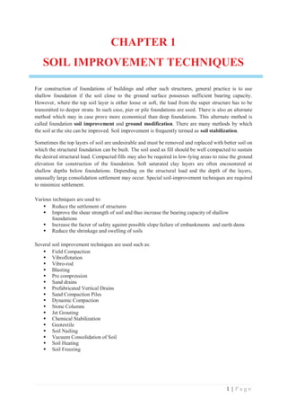


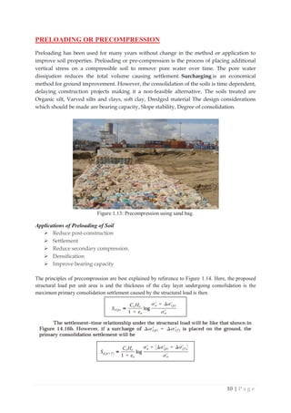


![13 | P a g e
EXAMPLE 1
During the construction of a highway bridge, the average permanent load on the clay layer is expected
to increase by about 115 KN/m2
. The average effective overburden pressure at the middle of the clay
layer is 210 KN/m2
. Here Hc = 6 m, Cc = 0.28, Ղ= 0.9 and ܥ௩ = 0.36 m2
/mo. The clay is normally
consolidated. Determine
a. Total primary consolidation settlement of the bridge without pre compression.
b. The surcharge, ΔߪԢሺሻ, needed to eliminate entire primary consolidation settlement in
nine months by pre compression.
SOLUTION
The total primary consolidation settlement maybe calculated from:
ܵሺሻ =
ு
ଵାՂ
log [
௱ఙାఙᇱሺሻ
௱ఙ
] =
ሺǤଶ଼ሻሺሻ
ଵାǤଽ
Ž‘‰ ሾ
ଶଵାଵଵହ
ଶଵ
ሿ
= 0.1677 m = 167.7 mm
We have
ܶజ =
ഔ௧మ
ுమ
ܥజ = .36 m2
/mo.
H = 3 m (two way drainage)
ݐଶ ൌ ͻmo.
Hence,
ܶజ =
ሺǤଷሻሺଽሻ
ଷమ = 0.36
According to figure 14.19 for ܶజ = 0.36, the value of U is 47%. Now
ȟߪԢሺሻ= 115 KN/m2
And
ߪԢ= 210 KN /m2
So
ఙᇱሺሻ
௱ఙᇱ
=
ଵଵହ
ଶଵ
= 0.548
According to figure 14.17. For U is 47% ǡ ȟߪԢሺሻ/ ߂ߪԢ= 0.548,
ȟߪԢሺሻ/ ߂ߪԢሺሻ≈1.8;
ȟߪԢሺሻ= (1.8) (115) = 207 KN /m2](https://image.slidesharecdn.com/ce441notes-250816192045-17023ddc/85/Soil-Improvement-Techniques-Note-Rabbi-13-320.jpg)


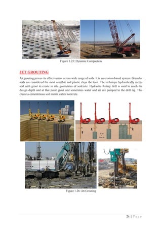
![25 | P a g e
There are three traditional jet grout systems:
• The single-fluid system: A high-velocity cement slurry grout is used to erode and mix the soil. This
system is most effective in cohesion less soil
• The double-fluid system: The high-velocity cement slurry jet is surrounded with an air jet. The
shroud of air increases the erosion efficiency. The double-fluid system is more effective in cohesive
soils than the single-fluid system.
• The triple-fluid system: A high-velocity water jet surrounded by an air jet is used to erode the soil.
A lower jet injects the cement slurry at a reduced pressure. Separating the erosion process from the
grouting process results in higher quality soilcrete and is the most effective system in cohesive soils.
Figure 1.27: Different types of Jet Grouting System
CHEMICAL STABILIZATION
The physical properties of soils can often economically be improved by use of chemical admixtures.
Some of more widely used admixtures include lime, cement and fly ash. The process of soil
stabilization first involves mixing with the soil a suitable additive which changes its property and then
compacting the admixture suitably. The method is applicable only for the soils in shallow foundations
or the base course of roads.
LIME STABILIZATION
Lime stabilization improves the strength, stiffness and durability of fine grained materials. Lime has
been used as a stabilizer for soils in the base courses of pavement system, under concrete foundation,
on embankment slopes and canal linings. Adding lime to soil produces a maximum density under
higher optimum moisture content than in the untreated soil. Moreover, lime produces a decrease in
plasticity index. Lime stabilization has been extensively used to decrease swilling potential and
swilling pressure in clays.
The types of lime commonly used to stabilize fine-grained soils are hydrated high-calcium lime
[Ca(OH)2], calcitic quicklime (CaO), monohydrated dolomitic lime [Ca(OH)2.MgO] and dolomitic
quicklime. The quantity of lime used to stabilize most soils usually is in the range from 5 to 10%.
When lime is added to clayey soils, two pozzolanic chemical reactions occur: cation exchange and
flocculation–agglomeration. In the cation exchange and flocculation–agglomeration reactions, the
monovalent cations generally associated with clays are replaced by the divalent calcium ions. The
cations can be arranged in a series based on their affinity for exchange:](https://image.slidesharecdn.com/ce441notes-250816192045-17023ddc/85/Soil-Improvement-Techniques-Note-Rabbi-25-320.jpg)


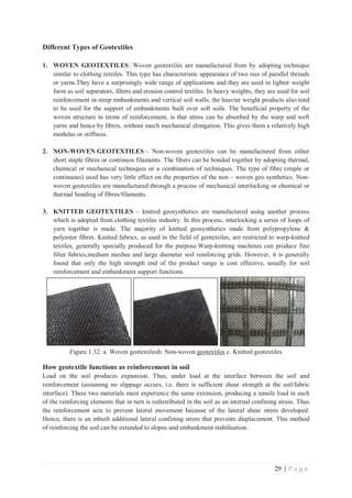


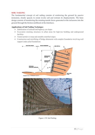


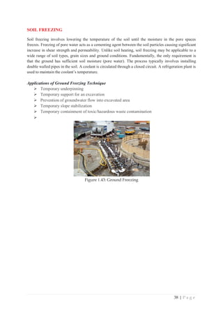


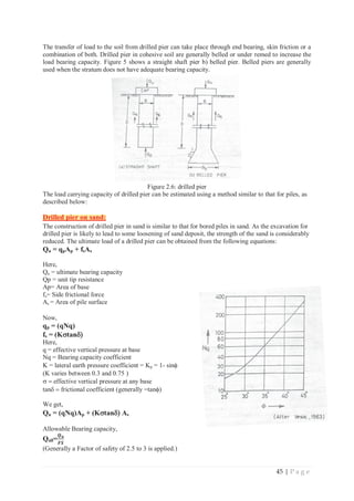
![46 | P a g e
Drilled pier on Clay:
The analysis of drilled pier on clay is similar to that of bored pile on clay. The ultimate load is given
by the following equations:
Qu = qpAp + fsAs
Qu = CNcAp + D
DcAs
Here,
C = Undrained cohesion
c = average undrained cohesion on the shaft
D = adehion factor
Nc= Bearing capacity factor
The value of Nc depends upon D/B1. B1 is the diameter of the bottom.
Values of Nc (After Teng 1962)
D/B1 0 0.5 1.0 1.5 2.0 2.5 3.0 4.30 and above
Nc 6.2 7.1 7.7 8.1 8.4 8.6 8.8 9.0
The value of D generally varies between 0.15 and 0.50 depending upon the drilling method and type
of pier. An average value of 4 is usually taken.
If the shaft is provided with bell, only the straight portion is considered for friction (adhesion). For
belled shaft drilled dry, the upper limit of unit adhesion is 40 kN/ m2
nad that for the belled shafts
drilled with slurry is 25 KN/ m2
. For straight shafts excavation dry, the upper limit is 100KN/ m2
.
Allowable Bearing capacity,
Qall=
ࡽ࢛
ࡲࡿ
(Generally a Factor of safety of 3 is applied.)
EXAMPLE 1:
A straight shaft drilled pier, 1 m in diameter is constructed in a deposit consisting of loose
sand overlying dense sand. Determine the allowable load. (FS = 3)
Solution:
Let us take critical depth Dc = 10 B = 10 m
Qu = (qNq) Ap + (KVtanG As
q = effective vertical pressure at the base = (8X17) + (2 X 21) = 178 KN/m2
From graph, Nq = 140 for I = 40o
Qu = [178 x 140 x π/4 X (1)2
] + [{0.5 x (π x 1.0) x 0.58 (0.5 x 136 x 8.0)]} + {0.4 x π 1.0 x 0.84 ( 0.5
x (136 + 178) x 2.0 x 178 x 2.0}]
= 220740 KN
Qall=
ொೠ
ிௌ
ଶସ
ଷ
= 6913 KN
EXAMPLE 1:
C = Undrained cohesion
0.15 and 0.50 ype
of pier 4](https://image.slidesharecdn.com/ce441notes-250816192045-17023ddc/85/Soil-Improvement-Techniques-Note-Rabbi-46-320.jpg)
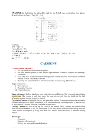
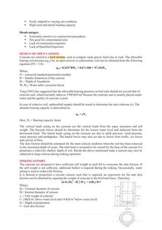

![50 | P a g e
EXAMPLE 3: Determine the outside diameter of an open caisson to be sunk through 40m of sand
and water to bed rock if the allowable bearing capacity is 2000KN/m2. The caisson receives a load of
50 MN from the superstructure. The mantle friction is 30KN/m2.
Test the feasibility of sinking. Also calculate the thickness of the seal.
Solution:
Solution:
From equilibrium in the vertical direction
Load from superstructure + self weight – frictional resistance – uplift force – base reaction = 0
or,
[(5000) + {(π/4) x Do
2
x (40) x (24)} – {(π Do) x (40) x (30)}- {(π/4) x Do
2
x (40) x (10)} – {(π/4) x
Do
2
x 2000}] = 0
or, Do
2
+ 3.33 Do – 44.23 = 0
or, Do = 5.19m
Let us adopt outside diameter as 6.0m
Feasibility of sinking:
We know:
(π/4) (Do
2
- Di
2
) D Jc = (πDo) D f
or, (π/4) (62
- Di
2
) x 40 x 24 = (π 6) x 40 x 30
or, 36 - Di
2
= 30
Di= 2.4m
Thickness of wall:
ǤିଶǤସ
ଶ
= 1.8m
Thickness of seal:
We know,
t = 0.59 Diට
ఙ
= 0.59 x 2.4 ට
ଶ
ଷହ
= 1.07m
Say 1.10m
CUTTING EDGE
The cutting edge is provided at the base of the open caisson to facilitate penetration. It also protects
the walls of the caisson against impact and obstacles encountered in its path during penetration. The
bevel is generally made 2 vertical to one horizontal. The cutting edges are usually made of angles and
plates of structural plates of structural steel or reinforced concrete and steel. As the sharp edges are
easily damaged, the blunt edges are commonly used. However, the angle of the edge should not be
greater than 35o
.
Figure: 2.6: cutting edge of open caisson](https://image.slidesharecdn.com/ce441notes-250816192045-17023ddc/85/Soil-Improvement-Techniques-Note-Rabbi-50-320.jpg)


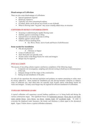

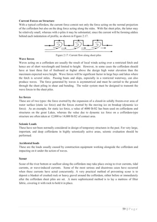

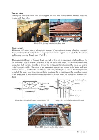
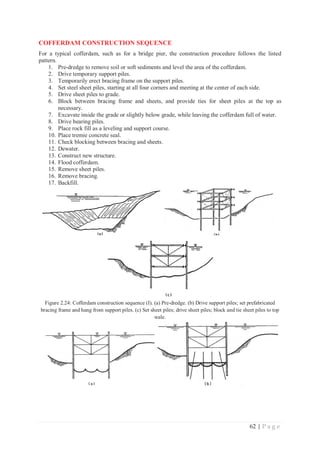


![Attack surfaces and attack tress[inform]](https://cdn.slidesharecdn.com/ss_thumbnails/lecture03-260108015941-a4dee53b-thumbnail.jpg?width=640&height=640&fit=bounds)


