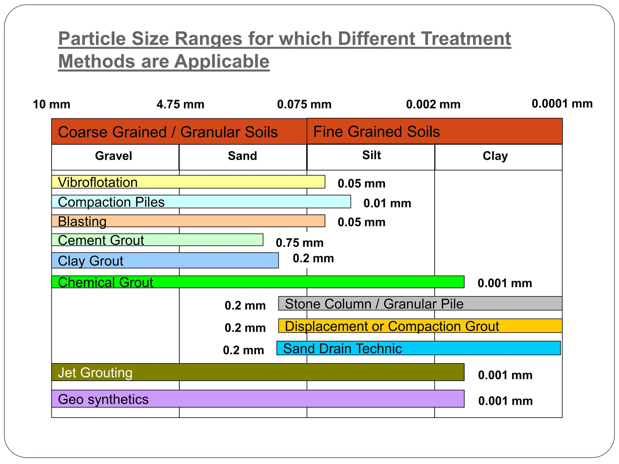
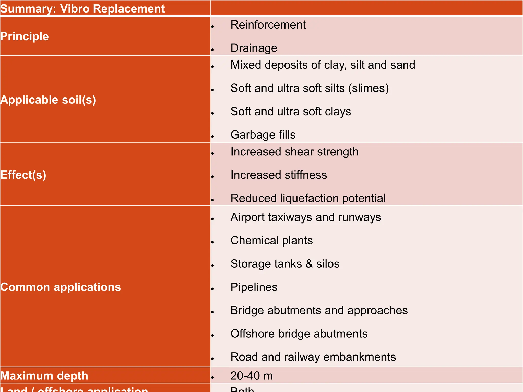
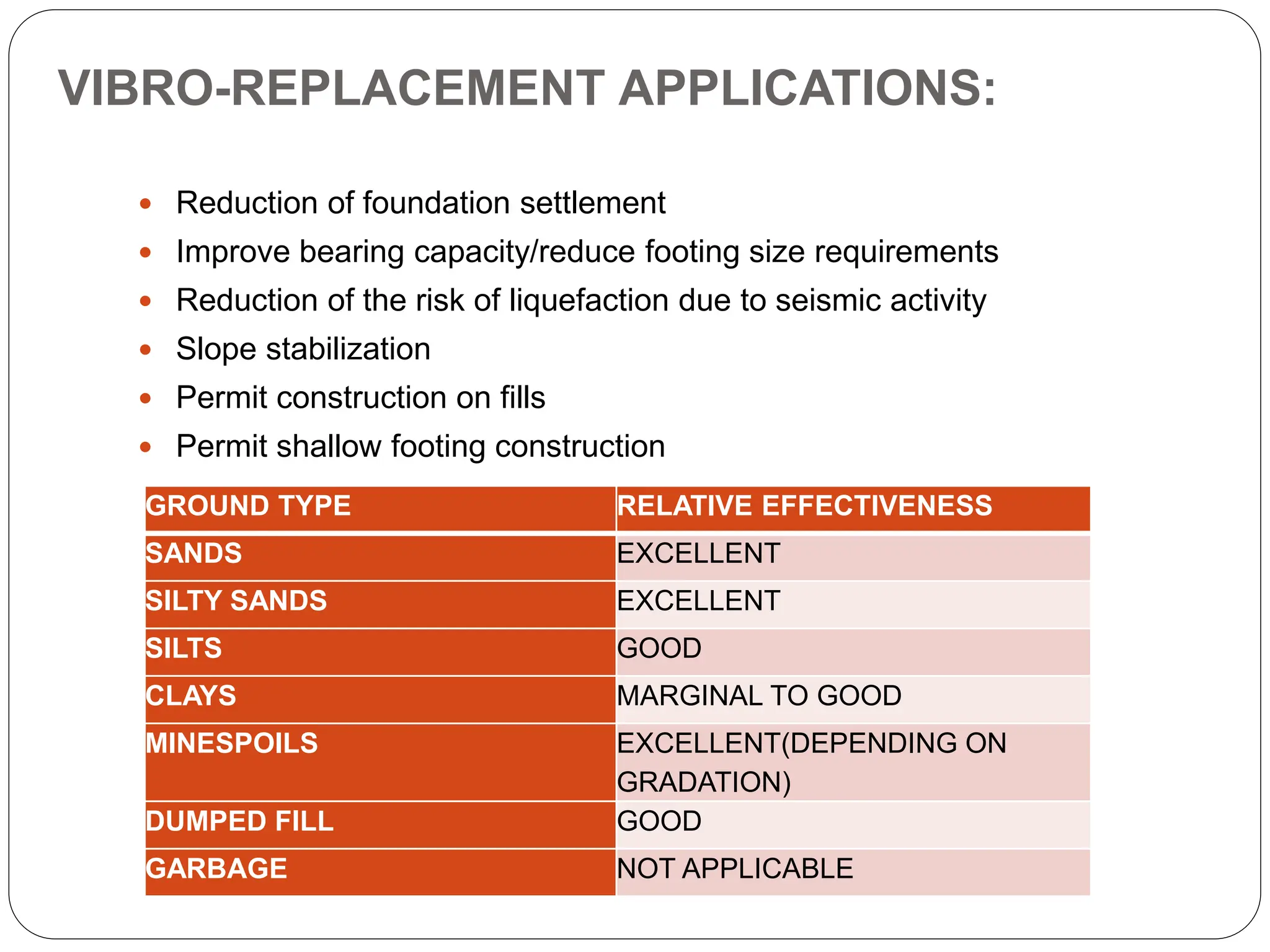
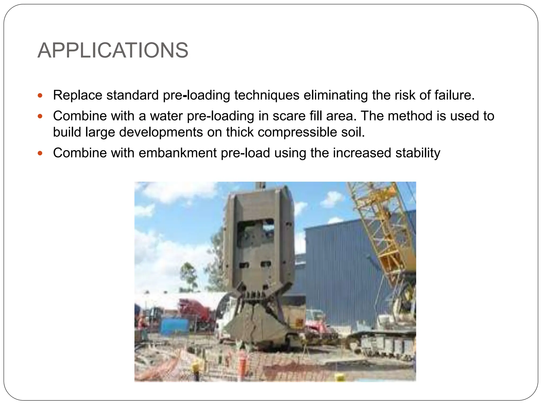
SOIL IMPROVEMENT
TECHNIQUES
Prepared By: Saurabh
shah
Code: SD-1710
VARIOUS SOIL IMPROVEMENT
TECHNIQUES
 Vibro-compaction increases the density of the soil by using powerful depth
vibrators.
 Vacuum consolidation is used for improving soft soils by using a vacuum
pump.
 Preloading method is used to remove pore water over time.
 Heating is used to form a crystalline or glass product by electric current.
 Ground freezing converts pore water to ice to increase their combined
strength and make them impervious.
 Vibro replacement stone columns improve the bearing capacity of soil
whereas Vibro displacement method displaces the soil.
 Electro osmosis makes water flow through fine grained soils.
 Electro kinetic stabilization is the application of electro osmosis.
 Reinforced soil steel is used for retaining structures, sloping walls, dams etc.
 seismic loading is suited for construction in seismically active regions.
 Mechanically stabilized earth structures create a reinforced soil mass.
 The geo methods like Geosynthesis, Geogrid etc.
 Soil nailing increases the shear strength of the in-situ soil and restrains its
displacement.
 Micro pile gives the structural support and used for repair/replacement of
existing foundations.
 Grouting is injection of pumpable materials to increase its rigidity. The jet
grouting is quite advanced in speed as well as techniques when compared
with the general grouting.
Particle Size Ranges for which Different Treatment
Methods are Applicable
Gravel Silt
Sand Clay
10 mm 4.75 mm 0.075 mm 0.002 mm 0.0001 mm
Vibroflotation
Blasting
Compaction Piles
0.05 mm
0.01 mm
0.05 mm
Cement Grout 0.75 mm
Coarse Grained / Granular Soils Fine Grained Soils
Clay Grout 0.2 mm
Chemical Grout 0.001 mm
Displacement or Compaction Grout
0.2 mm
Stone Column / Granular Pile
0.2 mm
Sand Drain Technic
0.2 mm
Jet Grouting
Geo synthetics
0.001 mm
0.001 mm
VIBRO-COMPACTION
 Vibro-compaction, sometimes referred to as Vibrofloation, is the
rearrangement of soil particles into a denser configuration by the use of
powerful depth vibration.
 Vibrocompaction is a ground improvement process for densifying loose
sands to create stable foundation soils.
 The principle behind vibrocompaction is simple. The combined action of
vibration and water saturation by jetting rearranges loose sand grains into a
more compact state.
 Vibrocompaction is performed with specially-designed vibrating probes.
 Both horizontal and vertical modes of vibration have been used in the past.
 The probe is first inserted into the ground by both jetting and vibration.
 After the probe reaches the required depth of compaction, granular material,
usually sand, is added from the ground surface to fill the void space created
by the vibrator.
 A compacted radial zone of granular material is created.
APPLICATIONS
 Reduction of foundation settlements.
 Reduction of risk of liquefaction due to seismic activity.
 Permit construction on granular fills.
VIBRO-REPLACEMENT STONE COLUMNS
 Vibro-Replacement extends the range of soils that can be improved by
vibratory techniques to include cohesive soils.
 Reinforcement of the soil with compacted granular columns or “stone
columns” is accomplished by the top-feed method.
 The important Vibro-replacement stone columns are Ground conditions,
Relative density, Degree of saturation, Permeation.
PRINCIPLES OF VIBRO-REPLACEMENT
 The stone columns and intervening soil form and integrated foundation
support system having low compressibility and improved load bearing
capacity.
 In cohesive soils, excess pore water pressure is readily dissipated by the
stone columns and for this reason, reduced settlements occur at a faster
rate than is normally the case with cohesive soils.
 There are different types of installation methods which can be broadly
classified in the following manner:
Wet top feed method
Dry bottom feed method
Offshore bottom feed method
Summary: Vibro Replacement
Principle
 Reinforcement
 Drainage
Applicable soil(s)
 Mixed deposits of clay, silt and sand
 Soft and ultra soft silts (slimes)
 Soft and ultra soft clays
 Garbage fills
Effect(s)
 Increased shear strength
 Increased stiffness
 Reduced liquefaction potential
Common applications
 Airport taxiways and runways
 Chemical plants
 Storage tanks & silos
 Pipelines
 Bridge abutments and approaches
 Offshore bridge abutments
 Road and railway embankments
Maximum depth  20-40 m
VIBRO-REPLACEMENT APPLICATIONS:
 Reduction of foundation settlement
 Improve bearing capacity/reduce footing size requirements
 Reduction of the risk of liquefaction due to seismic activity
 Slope stabilization
 Permit construction on fills
 Permit shallow footing construction
GROUND TYPE RELATIVE EFFECTIVENESS
SANDS EXCELLENT
SILTY SANDS EXCELLENT
SILTS GOOD
CLAYS MARGINAL TO GOOD
MINESPOILS EXCELLENT(DEPENDING ON
GRADATION)
DUMPED FILL GOOD
GARBAGE NOT APPLICABLE
VACCUM CONSOLIDATION
 Vacuum Consolidation is an effective means for improvement of
saturated soft soils.
 The soil site is covered with an airtight membrane and vacuum is
created underneath it by using dual venture and vacuum pump.
 The technology can provide an equivalent pre-loading of about 4.5m
high conventional surcharge fill.
 Vacuum-assisted consolidation preloads the soil by reducing the pore
pressure while maintaining a constant total stress.
APPLICATIONS
 Replace standard pre-loading techniques eliminating the risk of failure.
 Combine with a water pre-loading in scare fill area. The method is used to
build large developments on thick compressible soil.
 Combine with embankment pre-load using the increased stability
PRELOADING
 Preloading has been used for many years without change in the
method or application to improve soil properties.
 Preloading or pre-compression is the process of placing additional
vertical stress on a compressible soil to remove pore water over
time.
 The pore water dissipation reduces the total volume causing
settlement.
 Surcharging is an economical method for ground improvement.
However, the consolidation of the soils is time dependent, delaying
construction projects making it a non-feasible alternative.
 The soils treated are Organic silt, silts and clays, soft clay, Dredged
material.
 The design considerations which should be made are bearing
capacity, Slope stability, Degree of consolidation.
APPLICATIONS
 Reduce post-construction
 Settlement
 Reduce secondary compression.
 Densification
 Improve bearing capacity
HEATING
 Heating or vitrifaction breaks the soil particle down to form a crystalline
or glass product.
 It uses electrical current to heat the soil and modify the physical
characteristics of the soil. Heating soils permanently alters the
properties of the soil.
 Depending on the soil, temperatures can range between 300 and 1000
degree Celsius.
 The impact on adjacent structures and utilities should be considered
when heating is used.
APPLICATIONS
 Immobilization of radioactive or contaminated soil
 Densification and stabilization
GROUND FREEZING
 Ground freezing is the use of refrigeration to convert in-situ pore water
to ice.
 The ice then acts as a cement or glue, bonding together adjacent
particles of soil or blocks of rock to increase their combined strength and
make them impervious.
 The ground freezing considerations are Thermal analysis, Refrigeration
system geometry, Thermal properties of soil and rock, freezing rates,
Energy requirements, Coolant/ refrigerant distribution system analysis.
APPLICATIONS
 Temporary underpinning
 Temporary support for an excavation
 Prevention of groundwater flow into excavated area
 Temporary slope stabilization
 Temporary containment of toxic/hazardous waste contamination
MECHANICALLY STABILIZED EARTH
STRUCTURES
PRINCIPLES:
 The reinforcement is placed in horizontal layers between successive
layers of granular soil backfill. Each layer of backfill consists of one
or more compacted lifts.
 A free draining, non plastic backfill soil is required to ensure
adequate performance of the wall system.
 For walls reinforced with metallic strips, load is transferred from the
backfill soil to the strip reinforcement by shear along the interface.
 For walls with ribbed strips, bar mats, or grid reinforcement, load is
similarly transferred but an additional component of strength is
obtained through the passive resistance on the transverse members
of the reinforcement.
 Facing panels are typically square, rectangular, hexagonal or
cruciform in shape and are up to 4.5m ^2 in area.
 MSEW- Mechanically Stabilized Earth Walls, when the face batter is
generally steeper than 70 degrees.
 RSS- Reinforced Soil Slopes, when the face batter is shallower.
APPLICATIONS:
 RSS structures are cost effective alternatives for new construction
where the cost of embankment fill, right-of-way, and other consideration
may make a steeper slope desirable.
 Another use of reinforcement in engineered slopes is to improve
compaction at the edges of a slope to decrease the tendency for
surface sloughing.
SOIL NAILING
 The fundamental concept of soil nailing consists of reinforcing the
ground by passive inclusions, closely spaced, to create in-situ soil and
restrain its displacements.
 The basic design consists of transferring the resisting tensile forces
generated in the inclusions into the ground through the friction mobilized
at the interfaces.
Installation Sequence
The shoring requires drilling through the active zone into ground's passive zone.
1. A five foot cut is made to begin initial level of the nailing operation.
2. Holes are drilled into cut bank on about five foot centers.
3. Threaded bars are placed in shoring holes.
4. Threaded bars are grouted in place from bottom up.
5. Wire screen attached to rebar reinforcement installed over cut face.
6. First coating of shotcrete applied to cover protruding threaded bar.
7. Plates, washers, nuts positioned on shoring bars then locked down.
8. Second coat of shotcrete applied over soil and plates.
9. Repeat steps 1 through 8 for every lift of retaining wall construction.
(a) Excavation
(b) 1st stage Shotcreting (d) 2nd stage Shotcreting
(c) Nailing
(e) Excavation
(f) Nailed Soil Wall
APPLICATIONS:
 Stabilization of railroad and highway cut slopes
 Excavation retaining structures in urban areas for high-rise
building and underground facilities
 Tunnel portals in steep and unstable stratified slopes
 Construction and retrofitting of bridge abutments with complex
boundaries involving wall support under piled foundations
MICRO PILES
 Micro-piles are small diameter piles (up to 300 mm), with the
capability of sustaining high loads (compressive loads of over 5000
KN).
 The drilling equipment and methods allows micro – piles to be
drilled through virtually every ground conditions, natural and
artificial, with minimal vibration, disturbances and noise, at any
angle below horizontal.
 The equipment can be further adapted to operate in locations with
low headroom and severely restricted access.
APPLICATIONS:
 For Structural Support and stability
 Foundation for new structures
 Repair / Replacement of existing foundations
 Arresting / Prevention of movement
 Embankment, slope and landslide stabilization
 Soil strengthening and protection
GENERAL GROUTING
 Grouting is the injection of pumpable materials into a soil or rock formation to
change the physical characteristics of the formation.
 Grouting selection considerations are Site specific requirement, Soil type,
Soil groutability, Porosity.
 Grouting can be prevented by Collapse of granular soils, Settlement under
adjacent foundations, Utilities damage, Day lighting.
 Grouting can provide Increased soil strength and rigidity, reduced ground
movement, Predictable degree of improvement.
GROUTING TECHNIQUES:
The various injection grouting techniques used by grouting contractors for
ground improvement / ground modification can be summarized as follows:
 Permeation
 Compaction Grouting:
 Claquage
 Jet Grouting
GEOSYNTHETICS AS SOIL IMPROVEMENT
TECHNIQUE
 A planar product manufactured from polymeric materials used with rock,
earth, or other geotechnical engineering related material as an integral
part of a human-made project, structure, or system.
 Geosynthetics are usually sheet materials supplied in roll form and they
are used in many geotechnical applications.
 There are five categories - geogrids, geomembranes, geonets,
geotextiles and related products (materials such as erosion mats) that
do not fall naturally into one of the other four categories.
 There are six main functions that these materials can provide and many
products provide one of more of these, particularly the geocomposites
which, as the name suggests, are made up of multiple components.
Functions of Geosynthetics
1) Reinforcement
Functions of Geosynthetics
2) Hydraulic Barriers
Functions of Geosynthetics
3) Separation
Functions of Geosynthetics
3) Filtration
Functions of Geosynthetics
4) Drainage
Functions of Geosynthetics
5) Surface Erosion
 The Hindustan Petroleum Corporation Limited (HPCL) oil tank was
to be made on a site located at mundra.
 The site was plain ground with loose sandy strata.
 The load from the tank was very large and the soil investigation report
showed less S.B.C at the site.
 It was first decided to have stone column as ground improvement
technique.
 But the estimated cost of vibro-replacement stone column was very high
as the site was very large.
 So at the end the solution was made by deciding the geogrid laying at
the entire site to increase the S.B.C of the soil.
 This technique also helped the structure from uneven or differential
settlement.
Ground Improvement
Ground Improvement for Tank Foundation,
HPCL, Mundra, Gujarat
Subgrade Stabilization using Tensar Biaxial Geogrids
Talasari - Udhava Major Dist. Road, PWD, Maharashtra
FEW TECHNIQUES TO IMPROVE
SOIL PROPERTIES
Geogrid Wraparound Wall at CH. 48 KM & CH. 50 KM,
Lucknow - Muzaffarpur National Highway Project
Reinforced Soil System with Gabion Facia, MRPL, Mangalore
Gabion
Facia
GarmatTM
Reinforced
Soil
REFERENCES
BOOKS :
ENGINEERING WITH GEOSYNTHETICS- TATA MCGRAW HILL
PUBLICATIONS CO.PVT.LTD,NEW DELHI
SOIL ENGINEERING AND FOUNDATION ENGINEERING BY:
B.C.PUNMIA
NET :
THE BOMBAY TEXTILE RESEARCH ASSOCIATION, Mumbai-
(www.btraindia.com)
WIKIPEDIA.COM
GEOFABRICS LIMITED, U.K (www.geofabrics.com)
THANK YOU

118039141-Soil-Improvement-Techniques.ppt

  • 1.
    SOIL IMPROVEMENT TECHNIQUES Prepared By:Saurabh shah Code: SD-1710
  • 2.
    VARIOUS SOIL IMPROVEMENT TECHNIQUES Vibro-compaction increases the density of the soil by using powerful depth vibrators.  Vacuum consolidation is used for improving soft soils by using a vacuum pump.  Preloading method is used to remove pore water over time.  Heating is used to form a crystalline or glass product by electric current.  Ground freezing converts pore water to ice to increase their combined strength and make them impervious.  Vibro replacement stone columns improve the bearing capacity of soil whereas Vibro displacement method displaces the soil.  Electro osmosis makes water flow through fine grained soils.  Electro kinetic stabilization is the application of electro osmosis.  Reinforced soil steel is used for retaining structures, sloping walls, dams etc.
  • 3.
     seismic loadingis suited for construction in seismically active regions.  Mechanically stabilized earth structures create a reinforced soil mass.  The geo methods like Geosynthesis, Geogrid etc.  Soil nailing increases the shear strength of the in-situ soil and restrains its displacement.  Micro pile gives the structural support and used for repair/replacement of existing foundations.  Grouting is injection of pumpable materials to increase its rigidity. The jet grouting is quite advanced in speed as well as techniques when compared with the general grouting.
  • 4.
    Particle Size Rangesfor which Different Treatment Methods are Applicable Gravel Silt Sand Clay 10 mm 4.75 mm 0.075 mm 0.002 mm 0.0001 mm Vibroflotation Blasting Compaction Piles 0.05 mm 0.01 mm 0.05 mm Cement Grout 0.75 mm Coarse Grained / Granular Soils Fine Grained Soils Clay Grout 0.2 mm Chemical Grout 0.001 mm Displacement or Compaction Grout 0.2 mm Stone Column / Granular Pile 0.2 mm Sand Drain Technic 0.2 mm Jet Grouting Geo synthetics 0.001 mm 0.001 mm
  • 5.
    VIBRO-COMPACTION  Vibro-compaction, sometimesreferred to as Vibrofloation, is the rearrangement of soil particles into a denser configuration by the use of powerful depth vibration.  Vibrocompaction is a ground improvement process for densifying loose sands to create stable foundation soils.  The principle behind vibrocompaction is simple. The combined action of vibration and water saturation by jetting rearranges loose sand grains into a more compact state.  Vibrocompaction is performed with specially-designed vibrating probes.  Both horizontal and vertical modes of vibration have been used in the past.  The probe is first inserted into the ground by both jetting and vibration.  After the probe reaches the required depth of compaction, granular material, usually sand, is added from the ground surface to fill the void space created by the vibrator.  A compacted radial zone of granular material is created.
  • 6.
    APPLICATIONS  Reduction offoundation settlements.  Reduction of risk of liquefaction due to seismic activity.  Permit construction on granular fills.
  • 7.
    VIBRO-REPLACEMENT STONE COLUMNS Vibro-Replacement extends the range of soils that can be improved by vibratory techniques to include cohesive soils.  Reinforcement of the soil with compacted granular columns or “stone columns” is accomplished by the top-feed method.  The important Vibro-replacement stone columns are Ground conditions, Relative density, Degree of saturation, Permeation.
  • 9.
    PRINCIPLES OF VIBRO-REPLACEMENT The stone columns and intervening soil form and integrated foundation support system having low compressibility and improved load bearing capacity.  In cohesive soils, excess pore water pressure is readily dissipated by the stone columns and for this reason, reduced settlements occur at a faster rate than is normally the case with cohesive soils.  There are different types of installation methods which can be broadly classified in the following manner: Wet top feed method Dry bottom feed method Offshore bottom feed method
  • 10.
    Summary: Vibro Replacement Principle Reinforcement  Drainage Applicable soil(s)  Mixed deposits of clay, silt and sand  Soft and ultra soft silts (slimes)  Soft and ultra soft clays  Garbage fills Effect(s)  Increased shear strength  Increased stiffness  Reduced liquefaction potential Common applications  Airport taxiways and runways  Chemical plants  Storage tanks & silos  Pipelines  Bridge abutments and approaches  Offshore bridge abutments  Road and railway embankments Maximum depth  20-40 m
  • 11.
    VIBRO-REPLACEMENT APPLICATIONS:  Reductionof foundation settlement  Improve bearing capacity/reduce footing size requirements  Reduction of the risk of liquefaction due to seismic activity  Slope stabilization  Permit construction on fills  Permit shallow footing construction GROUND TYPE RELATIVE EFFECTIVENESS SANDS EXCELLENT SILTY SANDS EXCELLENT SILTS GOOD CLAYS MARGINAL TO GOOD MINESPOILS EXCELLENT(DEPENDING ON GRADATION) DUMPED FILL GOOD GARBAGE NOT APPLICABLE
  • 12.
    VACCUM CONSOLIDATION  VacuumConsolidation is an effective means for improvement of saturated soft soils.  The soil site is covered with an airtight membrane and vacuum is created underneath it by using dual venture and vacuum pump.  The technology can provide an equivalent pre-loading of about 4.5m high conventional surcharge fill.  Vacuum-assisted consolidation preloads the soil by reducing the pore pressure while maintaining a constant total stress.
  • 13.
    APPLICATIONS  Replace standardpre-loading techniques eliminating the risk of failure.  Combine with a water pre-loading in scare fill area. The method is used to build large developments on thick compressible soil.  Combine with embankment pre-load using the increased stability
  • 14.
    PRELOADING  Preloading hasbeen used for many years without change in the method or application to improve soil properties.  Preloading or pre-compression is the process of placing additional vertical stress on a compressible soil to remove pore water over time.  The pore water dissipation reduces the total volume causing settlement.  Surcharging is an economical method for ground improvement. However, the consolidation of the soils is time dependent, delaying construction projects making it a non-feasible alternative.  The soils treated are Organic silt, silts and clays, soft clay, Dredged material.  The design considerations which should be made are bearing capacity, Slope stability, Degree of consolidation.
  • 15.
    APPLICATIONS  Reduce post-construction Settlement  Reduce secondary compression.  Densification  Improve bearing capacity
  • 16.
    HEATING  Heating orvitrifaction breaks the soil particle down to form a crystalline or glass product.  It uses electrical current to heat the soil and modify the physical characteristics of the soil. Heating soils permanently alters the properties of the soil.  Depending on the soil, temperatures can range between 300 and 1000 degree Celsius.  The impact on adjacent structures and utilities should be considered when heating is used.
  • 17.
    APPLICATIONS  Immobilization ofradioactive or contaminated soil  Densification and stabilization
  • 18.
    GROUND FREEZING  Groundfreezing is the use of refrigeration to convert in-situ pore water to ice.  The ice then acts as a cement or glue, bonding together adjacent particles of soil or blocks of rock to increase their combined strength and make them impervious.  The ground freezing considerations are Thermal analysis, Refrigeration system geometry, Thermal properties of soil and rock, freezing rates, Energy requirements, Coolant/ refrigerant distribution system analysis.
  • 19.
    APPLICATIONS  Temporary underpinning Temporary support for an excavation  Prevention of groundwater flow into excavated area  Temporary slope stabilization  Temporary containment of toxic/hazardous waste contamination
  • 20.
    MECHANICALLY STABILIZED EARTH STRUCTURES PRINCIPLES: The reinforcement is placed in horizontal layers between successive layers of granular soil backfill. Each layer of backfill consists of one or more compacted lifts.  A free draining, non plastic backfill soil is required to ensure adequate performance of the wall system.  For walls reinforced with metallic strips, load is transferred from the backfill soil to the strip reinforcement by shear along the interface.  For walls with ribbed strips, bar mats, or grid reinforcement, load is similarly transferred but an additional component of strength is obtained through the passive resistance on the transverse members of the reinforcement.  Facing panels are typically square, rectangular, hexagonal or cruciform in shape and are up to 4.5m ^2 in area.  MSEW- Mechanically Stabilized Earth Walls, when the face batter is generally steeper than 70 degrees.  RSS- Reinforced Soil Slopes, when the face batter is shallower.
  • 21.
    APPLICATIONS:  RSS structuresare cost effective alternatives for new construction where the cost of embankment fill, right-of-way, and other consideration may make a steeper slope desirable.  Another use of reinforcement in engineered slopes is to improve compaction at the edges of a slope to decrease the tendency for surface sloughing.
  • 22.
    SOIL NAILING  Thefundamental concept of soil nailing consists of reinforcing the ground by passive inclusions, closely spaced, to create in-situ soil and restrain its displacements.  The basic design consists of transferring the resisting tensile forces generated in the inclusions into the ground through the friction mobilized at the interfaces.
  • 23.
    Installation Sequence The shoringrequires drilling through the active zone into ground's passive zone. 1. A five foot cut is made to begin initial level of the nailing operation. 2. Holes are drilled into cut bank on about five foot centers. 3. Threaded bars are placed in shoring holes. 4. Threaded bars are grouted in place from bottom up. 5. Wire screen attached to rebar reinforcement installed over cut face. 6. First coating of shotcrete applied to cover protruding threaded bar. 7. Plates, washers, nuts positioned on shoring bars then locked down. 8. Second coat of shotcrete applied over soil and plates. 9. Repeat steps 1 through 8 for every lift of retaining wall construction. (a) Excavation (b) 1st stage Shotcreting (d) 2nd stage Shotcreting (c) Nailing (e) Excavation (f) Nailed Soil Wall
  • 24.
    APPLICATIONS:  Stabilization ofrailroad and highway cut slopes  Excavation retaining structures in urban areas for high-rise building and underground facilities  Tunnel portals in steep and unstable stratified slopes  Construction and retrofitting of bridge abutments with complex boundaries involving wall support under piled foundations
  • 25.
    MICRO PILES  Micro-pilesare small diameter piles (up to 300 mm), with the capability of sustaining high loads (compressive loads of over 5000 KN).  The drilling equipment and methods allows micro – piles to be drilled through virtually every ground conditions, natural and artificial, with minimal vibration, disturbances and noise, at any angle below horizontal.  The equipment can be further adapted to operate in locations with low headroom and severely restricted access.
  • 26.
    APPLICATIONS:  For StructuralSupport and stability  Foundation for new structures  Repair / Replacement of existing foundations  Arresting / Prevention of movement  Embankment, slope and landslide stabilization  Soil strengthening and protection
  • 27.
    GENERAL GROUTING  Groutingis the injection of pumpable materials into a soil or rock formation to change the physical characteristics of the formation.  Grouting selection considerations are Site specific requirement, Soil type, Soil groutability, Porosity.  Grouting can be prevented by Collapse of granular soils, Settlement under adjacent foundations, Utilities damage, Day lighting.  Grouting can provide Increased soil strength and rigidity, reduced ground movement, Predictable degree of improvement.
  • 28.
    GROUTING TECHNIQUES: The variousinjection grouting techniques used by grouting contractors for ground improvement / ground modification can be summarized as follows:  Permeation  Compaction Grouting:  Claquage  Jet Grouting
  • 29.
    GEOSYNTHETICS AS SOILIMPROVEMENT TECHNIQUE
  • 30.
     A planarproduct manufactured from polymeric materials used with rock, earth, or other geotechnical engineering related material as an integral part of a human-made project, structure, or system.  Geosynthetics are usually sheet materials supplied in roll form and they are used in many geotechnical applications.  There are five categories - geogrids, geomembranes, geonets, geotextiles and related products (materials such as erosion mats) that do not fall naturally into one of the other four categories.  There are six main functions that these materials can provide and many products provide one of more of these, particularly the geocomposites which, as the name suggests, are made up of multiple components.
  • 33.
  • 34.
  • 35.
  • 36.
  • 37.
  • 38.
  • 39.
     The HindustanPetroleum Corporation Limited (HPCL) oil tank was to be made on a site located at mundra.  The site was plain ground with loose sandy strata.  The load from the tank was very large and the soil investigation report showed less S.B.C at the site.  It was first decided to have stone column as ground improvement technique.  But the estimated cost of vibro-replacement stone column was very high as the site was very large.  So at the end the solution was made by deciding the geogrid laying at the entire site to increase the S.B.C of the soil.  This technique also helped the structure from uneven or differential settlement.
  • 40.
    Ground Improvement Ground Improvementfor Tank Foundation, HPCL, Mundra, Gujarat
  • 41.
    Subgrade Stabilization usingTensar Biaxial Geogrids Talasari - Udhava Major Dist. Road, PWD, Maharashtra FEW TECHNIQUES TO IMPROVE SOIL PROPERTIES
  • 42.
    Geogrid Wraparound Wallat CH. 48 KM & CH. 50 KM, Lucknow - Muzaffarpur National Highway Project
  • 43.
    Reinforced Soil Systemwith Gabion Facia, MRPL, Mangalore Gabion Facia GarmatTM Reinforced Soil
  • 44.
    REFERENCES BOOKS : ENGINEERING WITHGEOSYNTHETICS- TATA MCGRAW HILL PUBLICATIONS CO.PVT.LTD,NEW DELHI SOIL ENGINEERING AND FOUNDATION ENGINEERING BY: B.C.PUNMIA NET : THE BOMBAY TEXTILE RESEARCH ASSOCIATION, Mumbai- (www.btraindia.com) WIKIPEDIA.COM GEOFABRICS LIMITED, U.K (www.geofabrics.com)
  • 45.