Downloaded 3,368 times

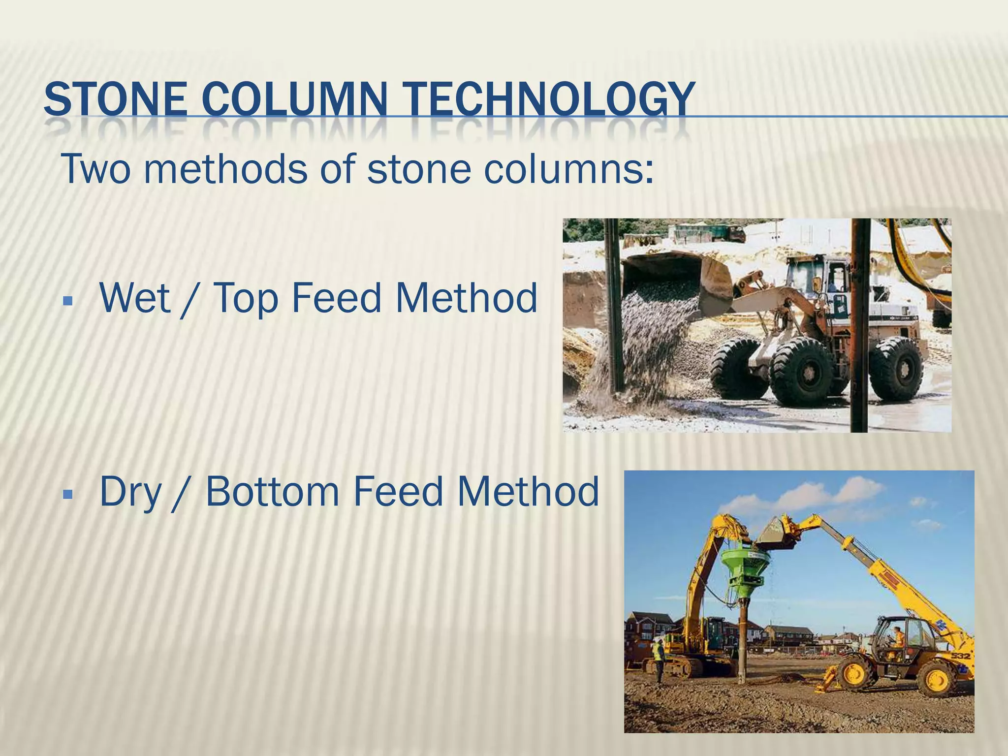
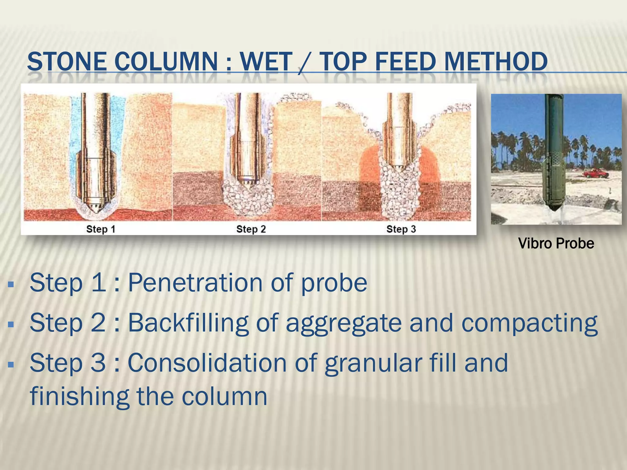
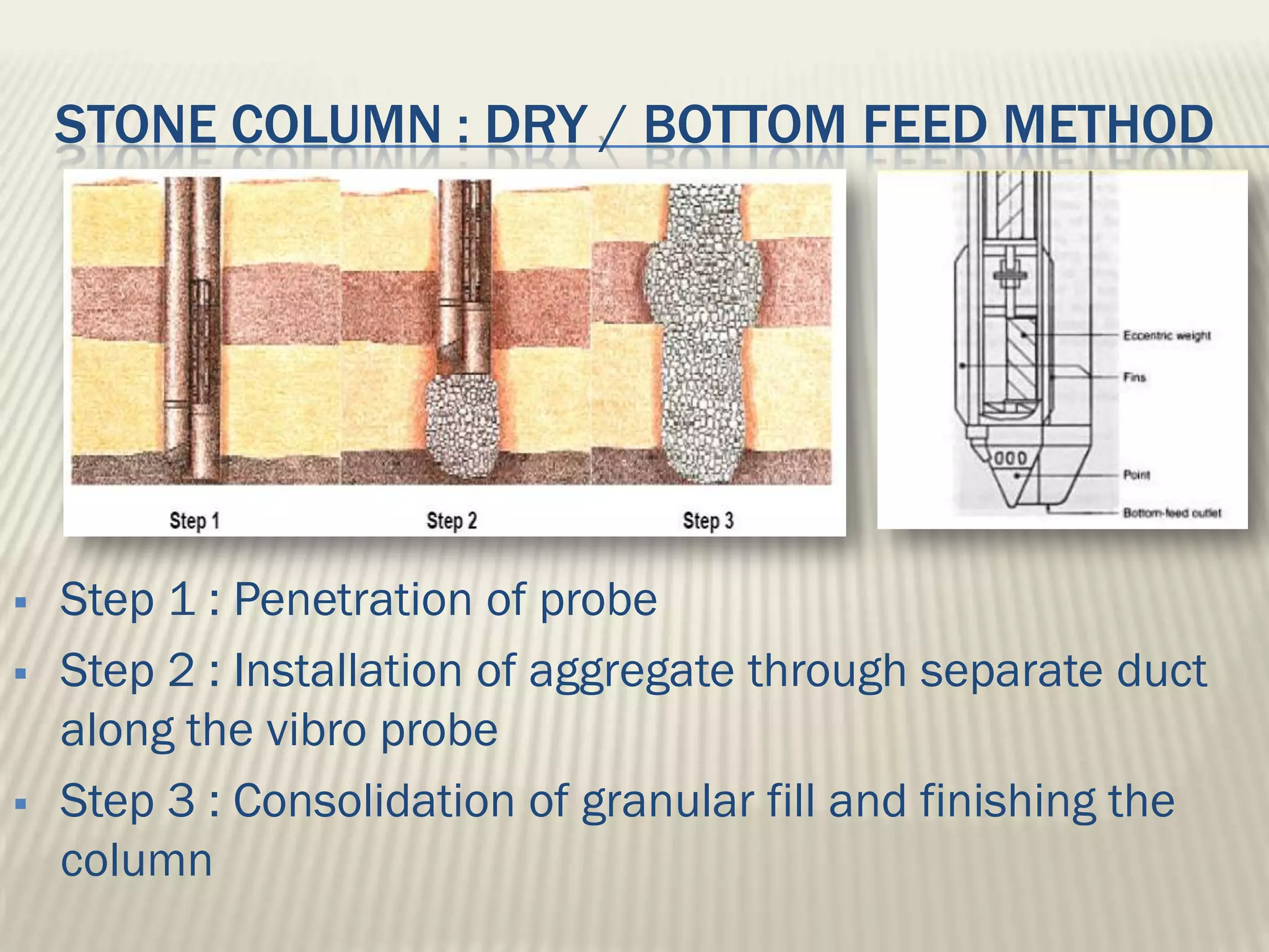
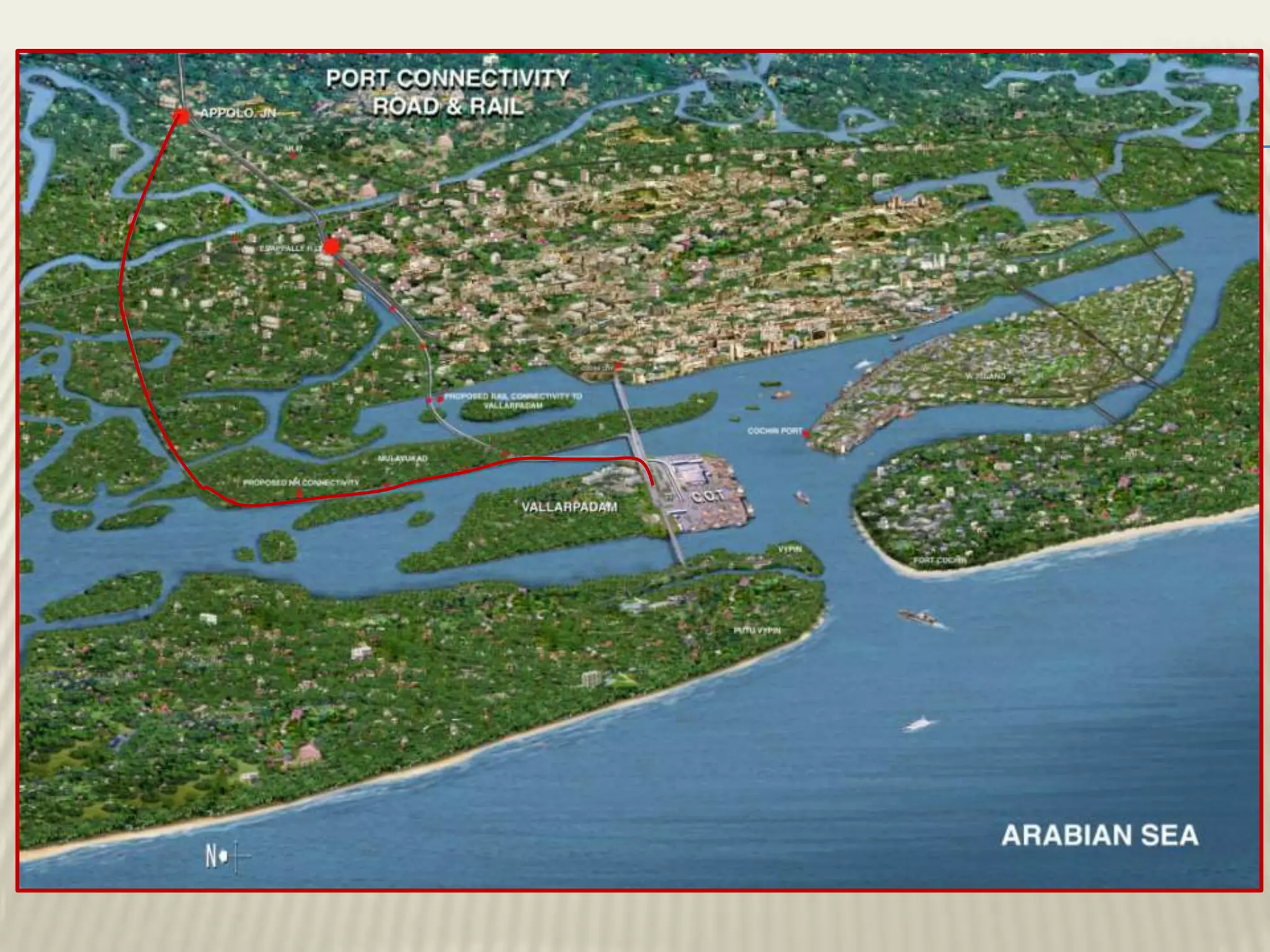
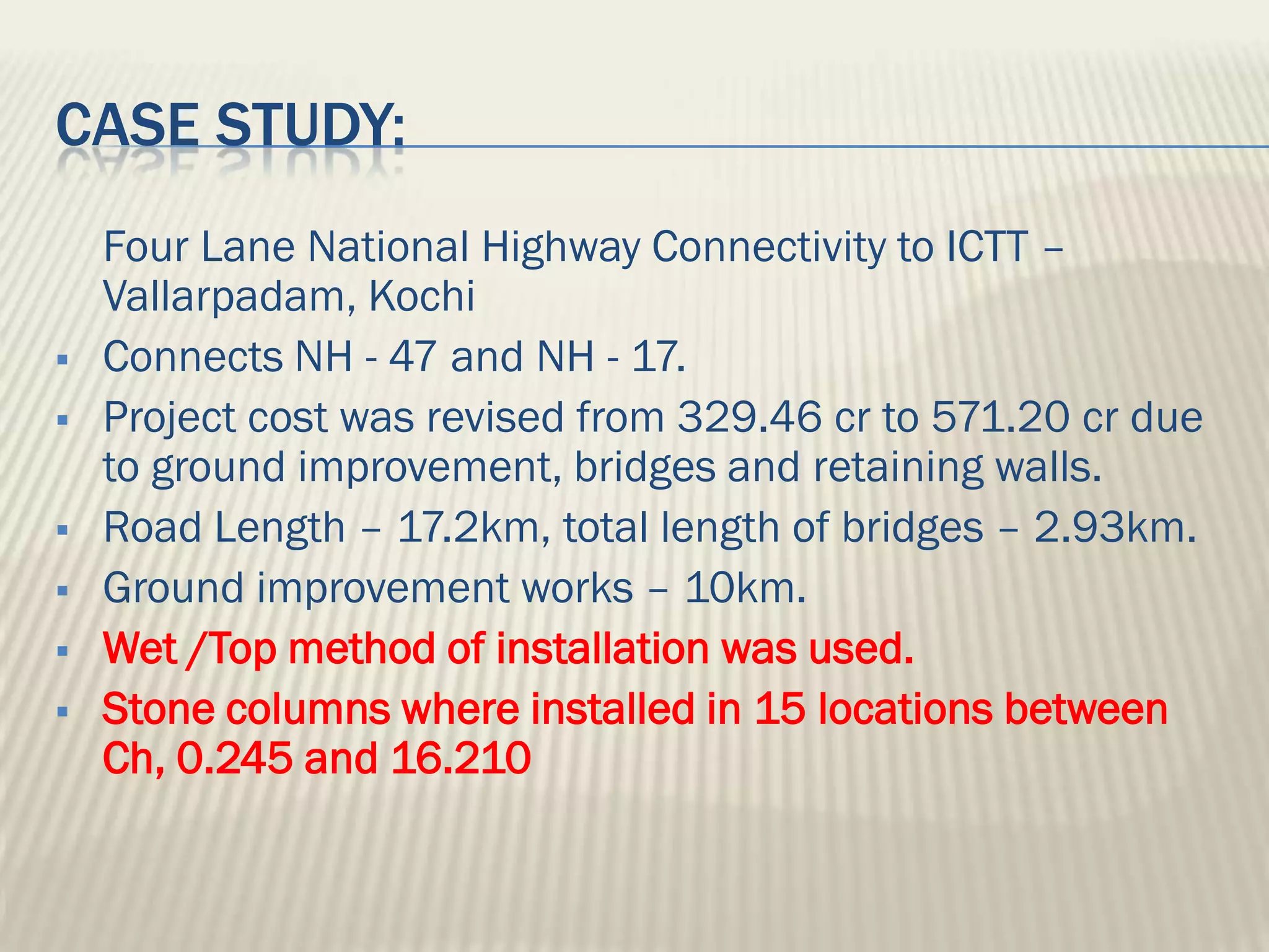
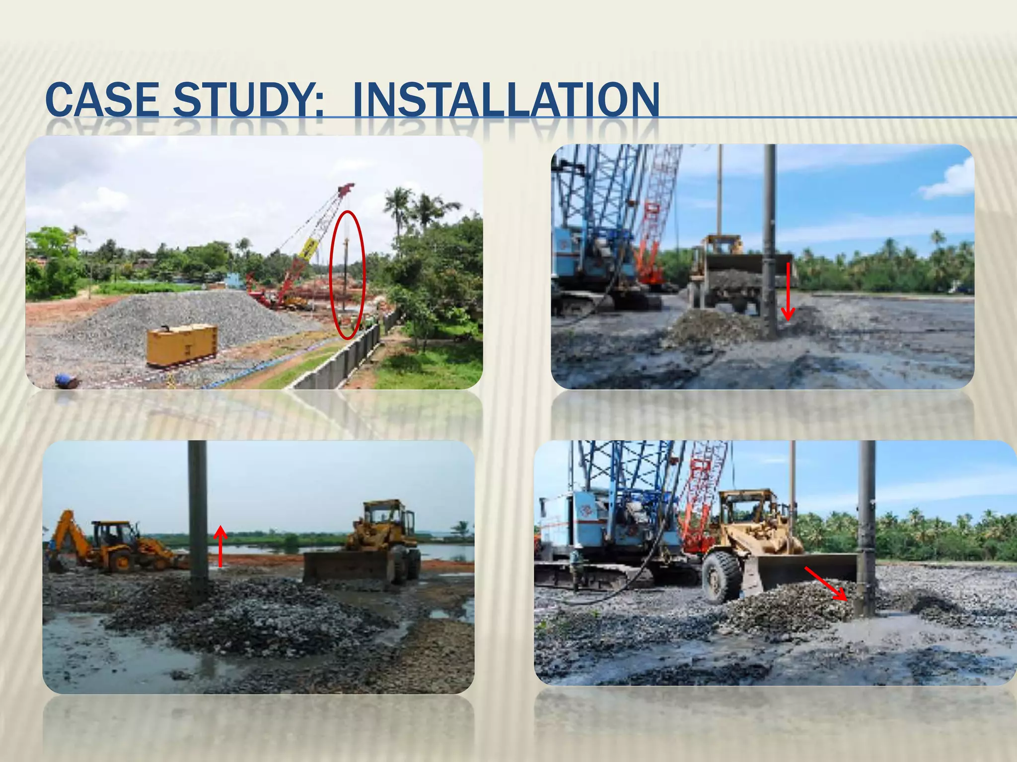
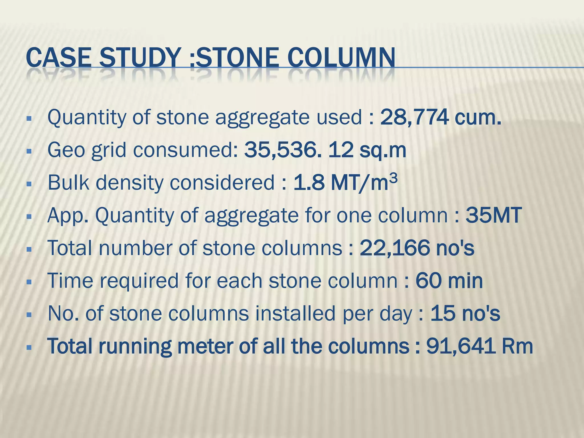

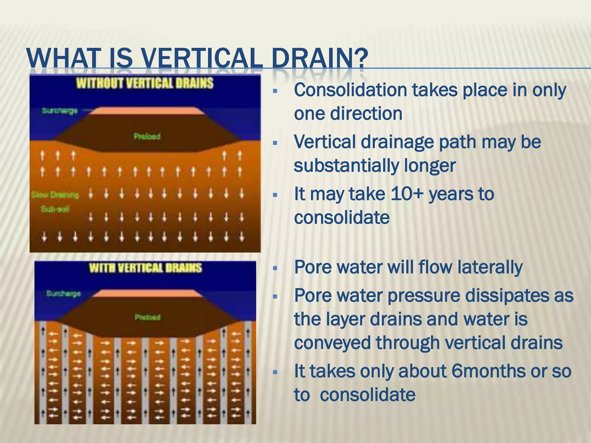

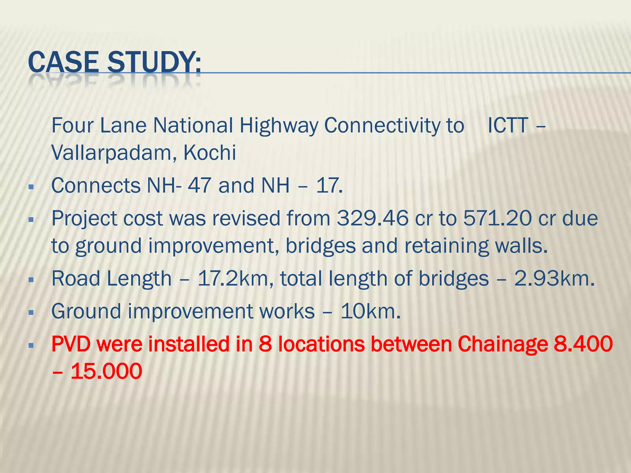
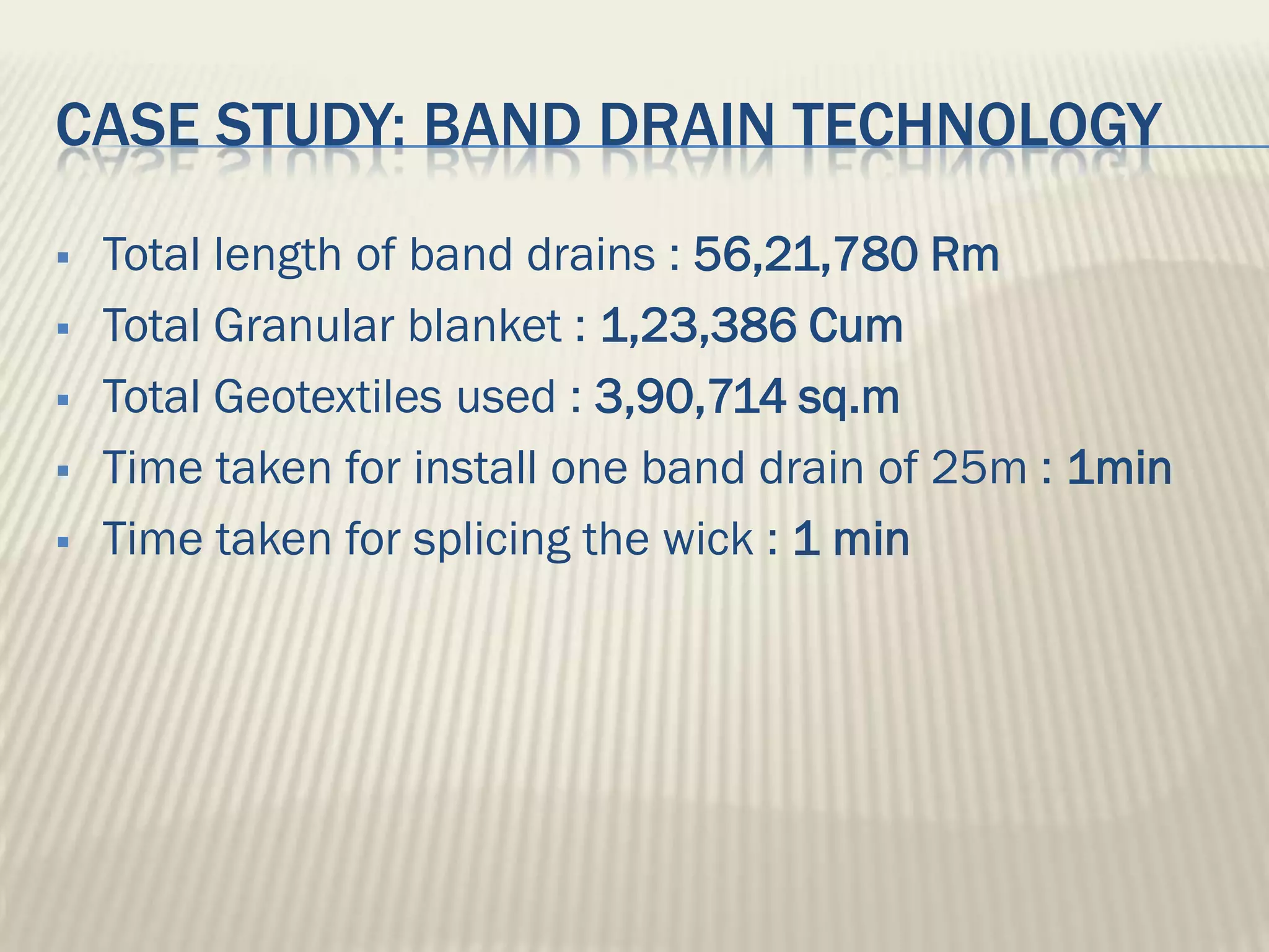


This document discusses ground improvement technologies including stone column and band drain technologies. Stone columns involve compacting aggregates into vertical columns to improve soil conditions and increase load capacity. Band drains involve installing prefabricated vertical drains to accelerate consolidation of loose, saturated clays by providing lateral drainage pathways. A case study describes a highway project in India where both stone columns and band drains were used over 10km to improve ground conditions.


![Geotechnical Engineering-II [Lec #17: Bearing Capacity of Soil]](https://cdn.slidesharecdn.com/ss_thumbnails/17-181123045836-thumbnail.jpg?width=640&height=640&fit=bounds)


