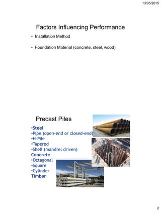
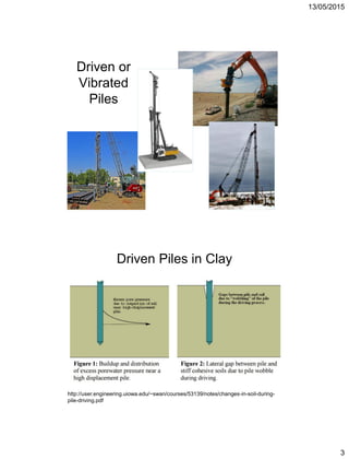
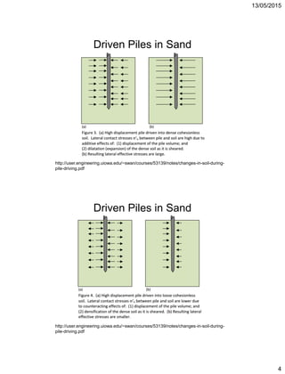
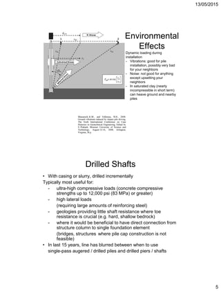
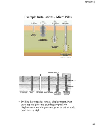
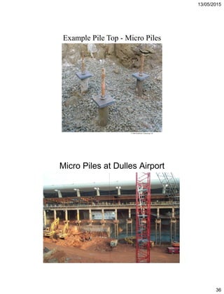
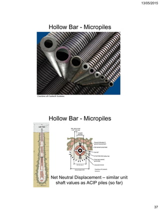
13/05/2015
1
Influence of Deep Foundation
Installation Methods
Presented by:
Morgan NeSmith, PE
Director or Engineering
mnesmith@berkelapg.com
http://www.berkelandcompany.com
To
2⁰ Congresso Internacional de
Fundaciones Profundas de Bolivia
Santa Cruz, Bolivia
May 2015
• Scope of Presentation
Precast Piles – steel, concrete
Cast-in-Place Foundations:
Drilled Shafts
Augered Cast-in-Place Piles / Continuous
Flight Auger Piles
Drilled Displacement Piles
Micropiles
13/05/2015
2
Factors Influencing Performance
• Installation Method
• Foundation Material (concrete, steel, wood)
Precast Piles
•Steel
•Pipe (open-end or closed-end)
•H-Pile
•Tapered
•Shell (mandrel driven)
Concrete
•Octagonal
•Square
•Cylinder
Timber
13/05/2015
3
Driven or
Vibrated
Piles
Driven Piles in Clay
http://user.engineering.uiowa.edu/~swan/courses/53139/notes/changes-in-soil-during-
pile-driving.pdf
13/05/2015
4
Driven Piles in Sand
http://user.engineering.uiowa.edu/~swan/courses/53139/notes/changes-in-soil-during-
pile-driving.pdf
Driven Piles in Sand
http://user.engineering.uiowa.edu/~swan/courses/53139/notes/changes-in-soil-during-
pile-driving.pdf
13/05/2015
5
Environmental
Effects
Dynamic loading during
installation
- Vibrations: good for pile
installation, possibly very bad
for your neighbors
- Noise: not good for anything
except upsetting your
neighbors
- In saturated clay (nearly
incompressible in short term)
can heave ground and nearby
piles
Drilled Shafts
• With casing or slurry, drilled incrementally
Typically most useful for:
- ultra-high compressive loads (concrete compressive
strengths up to 12,000 psi (83 MPa) or greater)
- high lateral loads
(requiring large amounts of reinforcing steel)
- geologies providing little shaft resistance where toe
resistance is crucial (e.g. hard, shallow bedrock)
- where it would be beneficial to have direct connection from
structure column to single foundation element
(bridges, structures where pile cap construction is not
feasible)
• In last 15 years, line has blurred between when to use
single-pass augered / drilled piles and drilled piers / shafts
13/05/2015
6
13/05/2015
7
Drilled Piers
Devon Energy - Oklahoma
Devon Energy WHQ
Drilled Piers
13/05/2015
8
Drilled Shaft – Example Reinforcing
Reinforcing
installed
PRIOR to
concrete
placement
Use concrete,
not grout,
typically
poured from
top or tremied
to bottom
13/05/2015
9
Shaft Typically Stabilized by
Casing or Slurry
Generally Neutral Displacement
(if constructed correctly!!!)
Casing and slurry can smooth soil surface lowering the friction coefficient
between shaft and soil
Tremied concrete also has lower bond strength with soil than other cast-in-place
methods (grouted or pressure grouted)
Not many places in North America where shafts bear in soil only – mostly in
rock – however some in Chicago (hard OC clay locally called hardpan) and
Mississippi (large deposits of OC clay) where belled piers are often efficient
Many designers neglect shaft and only consider end bearing (possibly very,
very conservative)
Reinforcing is set after drilling but before concreting so is typically full length
whether the shaft needs it or not (lateral loads typically resolved in the upper
6-m to 12-m of shaft)
13/05/2015
10
Cast-in-place piles installed by
single-pass, rotary drilling processes
Terminology for Cast-in-Place Piles
Continuous Flight Auger European Screw Piles
ACIP
aka Augercast
CFA
Intermediate (Partial) Displacement
Displacement Pile
Auger Pressure Grouted (APG) Pile System
• Cast-in-place piles grew out of pressure-
grouting processes at Intrusion-Prepakt,
late 1940s, early 1950s
• Patent granted to Raymond Patterson for
construction of cast-in-place piles by
pumping grout through a hollow-stem
auger.
• Licenses granted to Lee Truzillo and
Charles Berkel
“The Evolution of Cast in Place Piles”
November/December 2013 DFI Magazine
13/05/2015
11
• Gaspar Coelius granted patent for
cast-in-place “Screw” pile in 1960
Augered vs. Screwed or Displacement
Analogous to augered… .. And to displacement
From De Cock and Imbo, Transportation Research Record 1447
Excavated ACIP piles
13/05/2015
12
Stratigraphy?
Stratigraphy?
Residual soils
from soft to hard
to partially
weathered rock
(PWR = 100+
blows per 30 cm)
to bedrock
13/05/2015
13
(1) Stem augers hole
(4) Hollow stem
auger retracted
while grout pumped
into hole
(2) Grout pumped
under pressure
(3) Build up grout
head prior to
withdrawing auger
APG Pile Example Installation
2007 Berkel & Company
Cast-In-Place Pile
Seminar
(4) Hollow Stem
Auger is retracted
while grout is
pumped into hole
APG Pile Installation
(2) Grout is injected
under pressure
(1) Auger drills
hole
(3) Build up grout
head prior to
withdrawing auger
13/05/2015
14
Typical APG Pile Rig
Hollow Stem Auger
• Continuous flight auger
• 75 mm inside diameter pipe
• Auger diameters:
– Historical: 300 mm to 460 mm
– Typical: up to 610 cm = no problem
– Specialty: 760 cm to 1220 cm
• Auger section lengths: ~ 1 to 6 m
13/05/2015
15
JADE SIGNATURE - SUNNY ISLES BEACH, FL
90-cm Diameter (APG) Piles – 47-m Deep
Over 300 Installed in 20 weeks
To resist ~ 1000 metric tons compression
Auger Flights attached to Hollow Stem
13/05/2015
16
Drill Bits
• Basic Bit - Pengo bit
• Basic Rock Bit - fitted with carbide teeth
• Clay Flight Bit - for clay soils
Leads
Torque Arm
13/05/2015
17
Gearbox
• Hydraulically operated top
head drive
• Travels up and down the
leads
• Torques range from about 20
to 120 kN/m
• Weighs 1 to 5 metric tons
• Rotational speed ranges from
30 to 60 rpm
• Hydraulically
operated, positive
displacement piston-
ball valve pump
• Pump pressures
typically around 350
psi at pump outlet
• Stroke vols. typically
range from about 0.4
to 1.0 cubic feet per
stroke (up to 1.7)
• Grout hoses typically
2 to 3 inch diameter
• Can pump grout
several hundred feet
• Grout typically
delivered by ready mix
trucks
Grout Pump
13/05/2015
18
Typical Limited Headroom (LHR) Rig
• Used where overhead clearances
are at least 2.5 to 3 m
• Track-mounted or forklift mounted
drilling equipment
• Piles are drilled with auger sections
typically 1 to 3 m length
• Installation time longer than with
crane-mounted equipment (thus,
more expensive per foot
Neutral or
Negative
Displacement
• If proper equipment not
used, stress release
can occur
• Potential for release is
greater in alluvial or
marine sands than in
residual soils and stiff
clay
• Potential for release is
greater in segmental
(low-head room) than
single auger
13/05/2015
19
Neutral or
Negative
Displacement
• Can “suck” adjacent
piles if drilling too close
together
Fresh completed pile
Pile to be drilled
Maybe soil wants to displace
towards new pile being drilled as
horizontal confinement lowers
Pile to be drilled
Fresh pile may collapse into new
pile. Typically don’t drill adjacent
piles (closer than 6 diameters)
within 12 hours
ANCILLARY BENEFITS
Minimal Spoils
No Vibration
Low Noise
Easy to vary pile lengths to suit site conditions
Grouted bond to soils produces larger shaft
resistance than concrete-soil bond or driven
pile friction coefficients
13/05/2015
20
Fixed Mast Platforms
Drilled Displacement Piles
(full and partial displacement)
CFA (APG-FMC) Piles
Overview of
Drilling
Platform
and Sensors
13/05/2015
21
INSTALLATION PLATFORM
• 200 to 270 kN/m torque
• 18 to 36 metric tons downward force
• Fixed mast for stability, inclinometer
with display in operator’s compartment
• Grout pressure, measured at top of tools,
is displayed in operator’s compartment
• Real-time display of installation
parameters (depth, KDK pressure,
Installation Effort, grout pressure)
pressure
CAST-IN-PLACE PILES INSTALLED WITH A
FIXED MAST DRILLING PLATFORM (APG-FMC)
Wilkins, B., NeSmith, W.M,
Tebbenkamp, F., and Duncan, S. (2009)
Performance of Cast-in-place Piles
Installed with a Fixed Mast Drilling
Platform in Claystone – Glenrock WY
Proceedings of the DFI 34th Annual
Conference on Deep Foundations.
Kansas City MO, USA. 20 – 23 October
2010.
13/05/2015
22
CFA Example
• 6 to 9-m of weak, saturated,
compressible sand, silt and
clay
• Ground water at 1 – 2.5 m
depth
• Deep foundations for all major
units assumed from the outset
• Initial budget based on 1,600 x
9000-mm dia. drilled piers 3-m
into rock with temporary
casing.
• Considered drilled piers,
driven piles and auger cast
piles
Final decision:
** 600-mm dia. CFA pile w/
fixed mast platform**
Comments on CFA and Fixed Mast
Platforms
- Slower penetration and slower rotation with
fixed mast than with crane mounted APG piling
- Less spoils removed with CFA (maybe ~ 75%)
than with APG
- Slightly higher shaft values with fixed mast than
crane mounted systems
- Very economical to replace large pile caps or
drilled shafts
13/05/2015
23
Fixed-Mast Platform Crane-Mounted Platform
4’-0” +/-
30’-0” +/-
CONVENTIONAL ACIP TOOL DRILLED DISPLACEMENT TOOLINTERMEDIATE (PARTIAL)
DISPLACEMENT TOOL
APG and Displacement Tooling
Displacement leads to increased horizontal stresses (and densification)
for higher shaft resistance in many soils
Grout/soil interface is a more effective load transfer interface than pre-cast or steel/soil
13/05/2015
24
Berkel Displacement Pile Tool
Figure 1. Berkel Displacement Tool
Stem becomes
progressively larger,
terminating in the
displacing element
+- 1-m, regular flighting,
300-mm to 460-mm diameter
Reverse flighting
Displacing element. Same
diameter as the flighting
below
Stem, smaller than flighting
INSTALLATION METHOD
• Tool advances as a screw in low
to medium consistency soils.
• In dense soils, material
transported up the auger to the
displacing element. Material in
auger flights is compressed; thus
no stress relief in the zone
adjacent to the auger.
13/05/2015
25
INSTALLATION METHOD
• When the target level has been
reached, pumping of grout is
begun. Grout pressure is
monitored by the operator Lift
off and withdrawal rate are
varied to maintain pressure
where possible.
• Tool is rotated during
withdrawal and material which
falls around stem is captured
and displaced.
• Typically get grout return only
after tip is at or near ground
surface.
Soil Improvement Aspects Of Displacement Pile
Installation
• When displacement piles are installed in materials that exhibit
granular behavior, there is a significant increase in density in
the vicinity of the piles
• The increase is most pronounced in loose to medium dense
materials
• After a certain density, as the in-situ density of the materials
increases, the density percentage change goes down
• The increase in density is additive-the more piles that are
installed, the greater the increase
• Pressure grouted bond to soils produces larger shaft
resistance than concrete-soil bond or driven pile friction
coefficients
13/05/2015
26
2.1 METERS2.1 METERS1.8 METERS
1.8 METERS
0.46 M
0.46 M
0.46 M
46 CM BY 7.6 M COMPRESSION TEST PILE
46 CM BY 12.2 M EXTRA PILE
46 CM BY 12.2 M REACTION PILE
Improvement from Drilled Displacement Tool Installation
“AMBIENT” CONDITION-3D FROM PILE
0
5
10
15
20
25
30
35
0 25 50 75 100 125 150
Qc, tsf
DEPTH,ft
FINE SAND, TRACE TO SOME
SILT, OCCASIONAL THIN
SILT/CLAY LAYERS. AVERAGE
Qc = 3.1 MPa (32 tsf)
3.1 METERS
7.6 METERS
13/05/2015
27
AVERAGE CONE TIP RESISTANCE
COMPARISON OF CPT VALUES, 1D, 2D, 3D FROM PILE
0
5
10
15
20
25
30
35
40
0 25 50 75 100 125 150
CONETIP VALUE, TSF
DEPTH,FEET
3D OUT 2D OUT 1D OUTAVERAGE CONE TIP
RESISTANCE FROM 3.1 M TO
7.6 M (10 FEET TO 25 FEET)
3.1 MPa (32 TSF,
N = 8 BPF)
6.5 MPa (68 TSF,
N = 17 BPF)
8.1 MPa (84 TSF,
N = 21 BPF)
FINE SAND, TRACE
TO SOME SILT,
OCCASIONAL THIN
SILT/CLAY LAYERS
3.1 METERS
7.6 METERS
CPT VALUES AT 1D, 2D, 3D FROM PILE
COMPARISON OF CPT VALUES, 3D FROM PILE AND CENTER OF GROUP
0
5
10
15
20
25
30
35
40
0 25 50 75 100 125 150
CONETIP VALUE, TSF
DEPTH,FEET
3D OUT CENTER OF GROUP
3.1 MPa (32 TSF,
N = 8 BPF)
9.6 MPa (100 TSF,
N = 25 BPF)
3.1 METERS
7.6 METERS
AVERAGE CONE TIP
RESISTANCE FROM
3.1 M TO 7.6 M (10
FEET TO 25 FEET)
CPT VALUES AT 3D and CENTER OF GROUP
13/05/2015
28
ANCILLARY BENEFITS
Minimal Spoils
No Vibration
Low Noise
Easy to vary pile lengths to suit site
conditions
DOES THE BENEFIT
HOLD UP IN
RESIDUAL SOILS?
Some empirical
indications that shaft
resistance in medium
to dense sandy
residual soils are not
as high as expected
from marine, alluvial
and other younger
deposits.
13/05/2015
29
ORDER OF
INSTALLATION IN LARGE
GROUPS IS CRITICAL
DESIGN MODELS
UNDERESTIMATE GROUP
EFFECTS
Intermediate (Partial) Displacement
Pile System
13/05/2015
30
CONVENTIONAL ACIP TOOL DRILLED DISPLACEMENT TOOLINTERMEDIATE (PARTIAL)
DISPLACEMENT TOOL
APG and Displacement Tooling
Partial Displacement Auger Stem
Conventional ACIP Auger Stem
13/05/2015
31
Equipment/Process Summary
• Same installation platform as Drilled
Displacement Piles-high torque, crowd
• Large diameter stem, small flight dia.
(typically less than 2/3 ratio)
• Tooling is screwed into ground where
possible (displacement), drilled in where
necessary (excavation)
• Improve loose soils, limit stress relief in
dense soils
• Target spoil is less than 75% of neat
hole volume
• May be cast by volume (like APG piles)
or by pressure (like Drilled Displacement
piles)
13/05/2015
32
Efficiency Comparison to APG Pile
• Drilled displacement piles use more expensive
equipment
• Unit capacities from displacement systems can
be significantly higher than traditional APG piles
• Generally: If piles can be shorted and the
diameter can be decreased, displacement
systems can be more efficient (pending project
size)
Fixed-Mast Platform Crane-Mounted Platform
4’-0” +/-
30’-0” +/-
13/05/2015
33
Screening 1 – Insert the Screen
Screening 2 – Remove Foreign Objects
13/05/2015
34
Reinforcing Cage Placement
• In general, not as efficient as single-pass drilled
or augered systems but:
– High capacity (particularly for size)
– Installation in limited access and/or low headroom
– Minimal disturbance/vibration to adjacent structures
– Capability to penetrate subsurface obstructions
(very useful for rubble in urban fills and boulders in
glacial till)
– Can case through voids (useful in limestone with
large cavities)
Micro Piles (less than 300-mm dia)
• Refer to FHWA Micropile Design and Construction
Guidelines and DFI / ADSC Micropile 2010
Seminar (also see local contractors!)
13/05/2015
35
Example Installations - Micro Piles
Copyright © 2009 PT. Geonusa Utama
• Drilling is somewhat neutral displacement. Post
grouting and pressure grouting are positive
displacement and the pressure grout to soil or rock
bond is very high
13/05/2015
36
© 2008 Southwest Contracting Ltd
Example Pile Top - Micro Piles
Micro Piles at Dulles Airport
13/05/2015
37
Hollow Bar - Micropiles
Net Neutral Displacement – similar unit
shaft values as ACIP piles (so far)
13/05/2015
38
THE END – QUESTIONS?

Influence of deep foundation installation methods morgan nesmith

  • 1.
    13/05/2015 1 Influence of DeepFoundation Installation Methods Presented by: Morgan NeSmith, PE Director or Engineering mnesmith@berkelapg.com http://www.berkelandcompany.com To 2⁰ Congresso Internacional de Fundaciones Profundas de Bolivia Santa Cruz, Bolivia May 2015 • Scope of Presentation Precast Piles – steel, concrete Cast-in-Place Foundations: Drilled Shafts Augered Cast-in-Place Piles / Continuous Flight Auger Piles Drilled Displacement Piles Micropiles
  • 2.
    13/05/2015 2 Factors Influencing Performance •Installation Method • Foundation Material (concrete, steel, wood) Precast Piles •Steel •Pipe (open-end or closed-end) •H-Pile •Tapered •Shell (mandrel driven) Concrete •Octagonal •Square •Cylinder Timber
  • 3.
    13/05/2015 3 Driven or Vibrated Piles Driven Pilesin Clay http://user.engineering.uiowa.edu/~swan/courses/53139/notes/changes-in-soil-during- pile-driving.pdf
  • 4.
    13/05/2015 4 Driven Piles inSand http://user.engineering.uiowa.edu/~swan/courses/53139/notes/changes-in-soil-during- pile-driving.pdf Driven Piles in Sand http://user.engineering.uiowa.edu/~swan/courses/53139/notes/changes-in-soil-during- pile-driving.pdf
  • 5.
    13/05/2015 5 Environmental Effects Dynamic loading during installation -Vibrations: good for pile installation, possibly very bad for your neighbors - Noise: not good for anything except upsetting your neighbors - In saturated clay (nearly incompressible in short term) can heave ground and nearby piles Drilled Shafts • With casing or slurry, drilled incrementally Typically most useful for: - ultra-high compressive loads (concrete compressive strengths up to 12,000 psi (83 MPa) or greater) - high lateral loads (requiring large amounts of reinforcing steel) - geologies providing little shaft resistance where toe resistance is crucial (e.g. hard, shallow bedrock) - where it would be beneficial to have direct connection from structure column to single foundation element (bridges, structures where pile cap construction is not feasible) • In last 15 years, line has blurred between when to use single-pass augered / drilled piles and drilled piers / shafts
  • 6.
  • 7.
    13/05/2015 7 Drilled Piers Devon Energy- Oklahoma Devon Energy WHQ Drilled Piers
  • 8.
    13/05/2015 8 Drilled Shaft –Example Reinforcing Reinforcing installed PRIOR to concrete placement Use concrete, not grout, typically poured from top or tremied to bottom
  • 9.
    13/05/2015 9 Shaft Typically Stabilizedby Casing or Slurry Generally Neutral Displacement (if constructed correctly!!!) Casing and slurry can smooth soil surface lowering the friction coefficient between shaft and soil Tremied concrete also has lower bond strength with soil than other cast-in-place methods (grouted or pressure grouted) Not many places in North America where shafts bear in soil only – mostly in rock – however some in Chicago (hard OC clay locally called hardpan) and Mississippi (large deposits of OC clay) where belled piers are often efficient Many designers neglect shaft and only consider end bearing (possibly very, very conservative) Reinforcing is set after drilling but before concreting so is typically full length whether the shaft needs it or not (lateral loads typically resolved in the upper 6-m to 12-m of shaft)
  • 10.
    13/05/2015 10 Cast-in-place piles installedby single-pass, rotary drilling processes Terminology for Cast-in-Place Piles Continuous Flight Auger European Screw Piles ACIP aka Augercast CFA Intermediate (Partial) Displacement Displacement Pile Auger Pressure Grouted (APG) Pile System • Cast-in-place piles grew out of pressure- grouting processes at Intrusion-Prepakt, late 1940s, early 1950s • Patent granted to Raymond Patterson for construction of cast-in-place piles by pumping grout through a hollow-stem auger. • Licenses granted to Lee Truzillo and Charles Berkel “The Evolution of Cast in Place Piles” November/December 2013 DFI Magazine
  • 11.
    13/05/2015 11 • Gaspar Coeliusgranted patent for cast-in-place “Screw” pile in 1960 Augered vs. Screwed or Displacement Analogous to augered… .. And to displacement From De Cock and Imbo, Transportation Research Record 1447 Excavated ACIP piles
  • 12.
    13/05/2015 12 Stratigraphy? Stratigraphy? Residual soils from softto hard to partially weathered rock (PWR = 100+ blows per 30 cm) to bedrock
  • 13.
    13/05/2015 13 (1) Stem augershole (4) Hollow stem auger retracted while grout pumped into hole (2) Grout pumped under pressure (3) Build up grout head prior to withdrawing auger APG Pile Example Installation 2007 Berkel & Company Cast-In-Place Pile Seminar (4) Hollow Stem Auger is retracted while grout is pumped into hole APG Pile Installation (2) Grout is injected under pressure (1) Auger drills hole (3) Build up grout head prior to withdrawing auger
  • 14.
    13/05/2015 14 Typical APG PileRig Hollow Stem Auger • Continuous flight auger • 75 mm inside diameter pipe • Auger diameters: – Historical: 300 mm to 460 mm – Typical: up to 610 cm = no problem – Specialty: 760 cm to 1220 cm • Auger section lengths: ~ 1 to 6 m
  • 15.
    13/05/2015 15 JADE SIGNATURE -SUNNY ISLES BEACH, FL 90-cm Diameter (APG) Piles – 47-m Deep Over 300 Installed in 20 weeks To resist ~ 1000 metric tons compression Auger Flights attached to Hollow Stem
  • 16.
    13/05/2015 16 Drill Bits • BasicBit - Pengo bit • Basic Rock Bit - fitted with carbide teeth • Clay Flight Bit - for clay soils Leads Torque Arm
  • 17.
    13/05/2015 17 Gearbox • Hydraulically operatedtop head drive • Travels up and down the leads • Torques range from about 20 to 120 kN/m • Weighs 1 to 5 metric tons • Rotational speed ranges from 30 to 60 rpm • Hydraulically operated, positive displacement piston- ball valve pump • Pump pressures typically around 350 psi at pump outlet • Stroke vols. typically range from about 0.4 to 1.0 cubic feet per stroke (up to 1.7) • Grout hoses typically 2 to 3 inch diameter • Can pump grout several hundred feet • Grout typically delivered by ready mix trucks Grout Pump
  • 18.
    13/05/2015 18 Typical Limited Headroom(LHR) Rig • Used where overhead clearances are at least 2.5 to 3 m • Track-mounted or forklift mounted drilling equipment • Piles are drilled with auger sections typically 1 to 3 m length • Installation time longer than with crane-mounted equipment (thus, more expensive per foot Neutral or Negative Displacement • If proper equipment not used, stress release can occur • Potential for release is greater in alluvial or marine sands than in residual soils and stiff clay • Potential for release is greater in segmental (low-head room) than single auger
  • 19.
    13/05/2015 19 Neutral or Negative Displacement • Can“suck” adjacent piles if drilling too close together Fresh completed pile Pile to be drilled Maybe soil wants to displace towards new pile being drilled as horizontal confinement lowers Pile to be drilled Fresh pile may collapse into new pile. Typically don’t drill adjacent piles (closer than 6 diameters) within 12 hours ANCILLARY BENEFITS Minimal Spoils No Vibration Low Noise Easy to vary pile lengths to suit site conditions Grouted bond to soils produces larger shaft resistance than concrete-soil bond or driven pile friction coefficients
  • 20.
    13/05/2015 20 Fixed Mast Platforms DrilledDisplacement Piles (full and partial displacement) CFA (APG-FMC) Piles Overview of Drilling Platform and Sensors
  • 21.
    13/05/2015 21 INSTALLATION PLATFORM • 200to 270 kN/m torque • 18 to 36 metric tons downward force • Fixed mast for stability, inclinometer with display in operator’s compartment • Grout pressure, measured at top of tools, is displayed in operator’s compartment • Real-time display of installation parameters (depth, KDK pressure, Installation Effort, grout pressure) pressure CAST-IN-PLACE PILES INSTALLED WITH A FIXED MAST DRILLING PLATFORM (APG-FMC) Wilkins, B., NeSmith, W.M, Tebbenkamp, F., and Duncan, S. (2009) Performance of Cast-in-place Piles Installed with a Fixed Mast Drilling Platform in Claystone – Glenrock WY Proceedings of the DFI 34th Annual Conference on Deep Foundations. Kansas City MO, USA. 20 – 23 October 2010.
  • 22.
    13/05/2015 22 CFA Example • 6to 9-m of weak, saturated, compressible sand, silt and clay • Ground water at 1 – 2.5 m depth • Deep foundations for all major units assumed from the outset • Initial budget based on 1,600 x 9000-mm dia. drilled piers 3-m into rock with temporary casing. • Considered drilled piers, driven piles and auger cast piles Final decision: ** 600-mm dia. CFA pile w/ fixed mast platform** Comments on CFA and Fixed Mast Platforms - Slower penetration and slower rotation with fixed mast than with crane mounted APG piling - Less spoils removed with CFA (maybe ~ 75%) than with APG - Slightly higher shaft values with fixed mast than crane mounted systems - Very economical to replace large pile caps or drilled shafts
  • 23.
    13/05/2015 23 Fixed-Mast Platform Crane-MountedPlatform 4’-0” +/- 30’-0” +/- CONVENTIONAL ACIP TOOL DRILLED DISPLACEMENT TOOLINTERMEDIATE (PARTIAL) DISPLACEMENT TOOL APG and Displacement Tooling Displacement leads to increased horizontal stresses (and densification) for higher shaft resistance in many soils Grout/soil interface is a more effective load transfer interface than pre-cast or steel/soil
  • 24.
    13/05/2015 24 Berkel Displacement PileTool Figure 1. Berkel Displacement Tool Stem becomes progressively larger, terminating in the displacing element +- 1-m, regular flighting, 300-mm to 460-mm diameter Reverse flighting Displacing element. Same diameter as the flighting below Stem, smaller than flighting INSTALLATION METHOD • Tool advances as a screw in low to medium consistency soils. • In dense soils, material transported up the auger to the displacing element. Material in auger flights is compressed; thus no stress relief in the zone adjacent to the auger.
  • 25.
    13/05/2015 25 INSTALLATION METHOD • Whenthe target level has been reached, pumping of grout is begun. Grout pressure is monitored by the operator Lift off and withdrawal rate are varied to maintain pressure where possible. • Tool is rotated during withdrawal and material which falls around stem is captured and displaced. • Typically get grout return only after tip is at or near ground surface. Soil Improvement Aspects Of Displacement Pile Installation • When displacement piles are installed in materials that exhibit granular behavior, there is a significant increase in density in the vicinity of the piles • The increase is most pronounced in loose to medium dense materials • After a certain density, as the in-situ density of the materials increases, the density percentage change goes down • The increase in density is additive-the more piles that are installed, the greater the increase • Pressure grouted bond to soils produces larger shaft resistance than concrete-soil bond or driven pile friction coefficients
  • 26.
    13/05/2015 26 2.1 METERS2.1 METERS1.8METERS 1.8 METERS 0.46 M 0.46 M 0.46 M 46 CM BY 7.6 M COMPRESSION TEST PILE 46 CM BY 12.2 M EXTRA PILE 46 CM BY 12.2 M EXTRA PILE 46 CM BY 12.2 M REACTION PILE Improvement from Drilled Displacement Tool Installation “AMBIENT” CONDITION-3D FROM PILE 0 5 10 15 20 25 30 35 0 25 50 75 100 125 150 Qc, tsf DEPTH,ft FINE SAND, TRACE TO SOME SILT, OCCASIONAL THIN SILT/CLAY LAYERS. AVERAGE Qc = 3.1 MPa (32 tsf) 3.1 METERS 7.6 METERS
  • 27.
    13/05/2015 27 AVERAGE CONE TIPRESISTANCE COMPARISON OF CPT VALUES, 1D, 2D, 3D FROM PILE 0 5 10 15 20 25 30 35 40 0 25 50 75 100 125 150 CONETIP VALUE, TSF DEPTH,FEET 3D OUT 2D OUT 1D OUTAVERAGE CONE TIP RESISTANCE FROM 3.1 M TO 7.6 M (10 FEET TO 25 FEET) 3.1 MPa (32 TSF, N = 8 BPF) 6.5 MPa (68 TSF, N = 17 BPF) 8.1 MPa (84 TSF, N = 21 BPF) FINE SAND, TRACE TO SOME SILT, OCCASIONAL THIN SILT/CLAY LAYERS 3.1 METERS 7.6 METERS CPT VALUES AT 1D, 2D, 3D FROM PILE COMPARISON OF CPT VALUES, 3D FROM PILE AND CENTER OF GROUP 0 5 10 15 20 25 30 35 40 0 25 50 75 100 125 150 CONETIP VALUE, TSF DEPTH,FEET 3D OUT CENTER OF GROUP 3.1 MPa (32 TSF, N = 8 BPF) 9.6 MPa (100 TSF, N = 25 BPF) 3.1 METERS 7.6 METERS AVERAGE CONE TIP RESISTANCE FROM 3.1 M TO 7.6 M (10 FEET TO 25 FEET) CPT VALUES AT 3D and CENTER OF GROUP
  • 28.
    13/05/2015 28 ANCILLARY BENEFITS Minimal Spoils NoVibration Low Noise Easy to vary pile lengths to suit site conditions DOES THE BENEFIT HOLD UP IN RESIDUAL SOILS? Some empirical indications that shaft resistance in medium to dense sandy residual soils are not as high as expected from marine, alluvial and other younger deposits.
  • 29.
    13/05/2015 29 ORDER OF INSTALLATION INLARGE GROUPS IS CRITICAL DESIGN MODELS UNDERESTIMATE GROUP EFFECTS Intermediate (Partial) Displacement Pile System
  • 30.
    13/05/2015 30 CONVENTIONAL ACIP TOOLDRILLED DISPLACEMENT TOOLINTERMEDIATE (PARTIAL) DISPLACEMENT TOOL APG and Displacement Tooling Partial Displacement Auger Stem Conventional ACIP Auger Stem
  • 31.
    13/05/2015 31 Equipment/Process Summary • Sameinstallation platform as Drilled Displacement Piles-high torque, crowd • Large diameter stem, small flight dia. (typically less than 2/3 ratio) • Tooling is screwed into ground where possible (displacement), drilled in where necessary (excavation) • Improve loose soils, limit stress relief in dense soils • Target spoil is less than 75% of neat hole volume • May be cast by volume (like APG piles) or by pressure (like Drilled Displacement piles)
  • 32.
    13/05/2015 32 Efficiency Comparison toAPG Pile • Drilled displacement piles use more expensive equipment • Unit capacities from displacement systems can be significantly higher than traditional APG piles • Generally: If piles can be shorted and the diameter can be decreased, displacement systems can be more efficient (pending project size) Fixed-Mast Platform Crane-Mounted Platform 4’-0” +/- 30’-0” +/-
  • 33.
    13/05/2015 33 Screening 1 –Insert the Screen Screening 2 – Remove Foreign Objects
  • 34.
    13/05/2015 34 Reinforcing Cage Placement •In general, not as efficient as single-pass drilled or augered systems but: – High capacity (particularly for size) – Installation in limited access and/or low headroom – Minimal disturbance/vibration to adjacent structures – Capability to penetrate subsurface obstructions (very useful for rubble in urban fills and boulders in glacial till) – Can case through voids (useful in limestone with large cavities) Micro Piles (less than 300-mm dia) • Refer to FHWA Micropile Design and Construction Guidelines and DFI / ADSC Micropile 2010 Seminar (also see local contractors!)
  • 35.
    13/05/2015 35 Example Installations -Micro Piles Copyright © 2009 PT. Geonusa Utama • Drilling is somewhat neutral displacement. Post grouting and pressure grouting are positive displacement and the pressure grout to soil or rock bond is very high
  • 36.
    13/05/2015 36 © 2008 SouthwestContracting Ltd Example Pile Top - Micro Piles Micro Piles at Dulles Airport
  • 37.
    13/05/2015 37 Hollow Bar -Micropiles Hollow Bar - Micropiles Net Neutral Displacement – similar unit shaft values as ACIP piles (so far)
  • 38.