Downloaded 40 times


![`
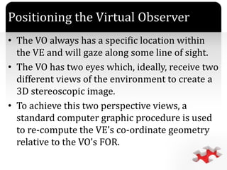
• The procedure used depends upon y]the
method employed to define the VO’s FOR
within the VE which may involve the use of
direction cosine, XYZ fixed angles, XYZ Euler
angles or Quaternions.
Positioning the Virtual Observer (contd..)](https://image.slidesharecdn.com/virtualreality-131009120905-phpapp01/85/Virtual-reality-7-320.jpg)


![`
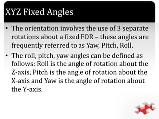
Quaternions
• It represents the rotation about an arbitrary
axis.
• We use 4D rotation and hence termed as
Quaternion. It is used to define the orientation
of the VO relative to the VE FOR.
• A quaternion ‘q’ is a quadruple of the real nos.
and defined as:
q = [s, v]
Where, s Scalar
v vector](https://image.slidesharecdn.com/virtualreality-131009120905-phpapp01/85/Virtual-reality-25-320.jpg)
![`
Quaternions (contd…)
• q = [s + xi + yj + zk]
• Here s, x, y and z are the real nos. and i, j and k
represents the unit vector in x, y and z
direction respectively.
• The two quaternions are equal if and only if
their corresponding terms are equal.
• q1 = [s1, v1] q2 = [s2, v2]
• q1 = [s1 + x1i + y1j + z1k]
• q2 = [s2 + x2i + y2j + z2k]](https://image.slidesharecdn.com/virtualreality-131009120905-phpapp01/85/Virtual-reality-26-320.jpg)
![`
Quaternions (contd…)
q1 q2 = [(S1S2 - V1V2), S1V2 + S2V1 + V1 X V2]](https://image.slidesharecdn.com/virtualreality-131009120905-phpapp01/85/Virtual-reality-27-320.jpg)

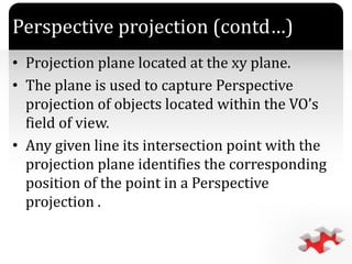


The document discusses the principles and components of 3D computer graphics, focusing on concepts such as virtual world space, positioning of the virtual observer, and methods of rendering graphics using techniques like direction cosines, fixed angles, Euler angles, and quaternions. It also addresses perspective projection, back-face removal, and the necessity of ambient light in rendering realistic images. Overall, it provides an overview of the mathematical and graphical foundations essential for creating 3D environments and images.